Research on suppress vibration of rotor misalignment with shear viscous damper①
2015-04-17HuangXiujin黄秀金HeLidong
Huang Xiujin(黄秀金), He Lidong
(Safety Engineering Research Center of the Ministry of Education, Beijing University of Chemical Technology, Beijing 100029, P.R.China)
Research on suppress vibration of rotor misalignment with shear viscous damper①
Huang Xiujin(黄秀金), He Lidong②
(Safety Engineering Research Center of the Ministry of Education, Beijing University of Chemical Technology, Beijing 100029, P.R.China)
A new type of shear viscous damper for rotating machinery is designed. The new damper with good stability and reliability can inhibit all kinds of frequency multiplication vibration caused by misalignment in the condition of non-stop machine. It analyzes and discusses the use of the shear viscous damper for misalignment vibration response inhibition with a finite element method, and experiments are extensively carried out with a laboratory test rig. Both the simulation and experimental results basically agree well in that, the damper can effectively control the misalignment vibration of the rotor system and improves the stability of the entire rotor system. Experimental results show the amplitude of one time running speed component decreases by 30%, and the two time running speed vibration has been basically eliminated.
shear viscous damper, misalignment, rotor system, vibration control
0 Introduction
In the practical engineering, shaft misalignment and rotor unbalance are major concerns in rotating machinery, which account for rotor system fault by over 60%[1]. The vibration due to such sources affects critical parts of the system such as bearings, gears, motor, seals, couplings, etc. Even if perfect alignment is achieved initially, it would not be possibly maintained during the operation of the machine due to various factors such as thermal distortion of housing supports of the bearings, differential thermal growth of machine parts, piping forces due to variation in pressure and temperature, movement of foundation, etc. Thus, a misalignment condition is virtually always present in machine-trains and it often needs processing in the downtime. Many researchers have given attention to shaft misalignment on its reasons[2,3], vibration characteristics and dynamic characteristics[4-10], the stability of shaft system[11-13], and the diagnostic analysis[14-17]. Wang, et al. invented a new type of high elevation and bearing lateral adjustment device for adjusting the bearing misalignment[18], but the device requires higher precision. Li, et al. proposed an electromagnetic auxiliary support, but it could control the two time running speed vibration component only, and the one time running speed vibration component still could not be controlled remarkably[19,20].
Many scholars have done extensive research on viscous shear vibration damper in controlling bridge construction vibration since the 1960s[21,22].Such damper has good stability ,reliability and obvious damping effect. On such basis, a new type of viscous dampers for rotating machinery is proposed to inhibit various frequency components vibration caused by shaft misalignment. Using the finite element method the shear viscous dampers damping effect is analyzed for shaft misalignment, and experiments are carried out for validation.
1 Designing of the shear viscous damper and finite element model of rotor misalignment
1.1 Designing and performance of the shear viscous damper
The structure of the shear viscous damper for rotating machinery is shown in Fig.1. It consists of shear elements, polymer viscous damping medium and other components. The rotor vibration passes to the shear elements through the bearing on the damper and dissipates in the damping medium, so achieves suppressing the vibration of the rotor system. The damper only acts as the equivalent of a secondary damping element acting on the shaft, adding few stiffness support, which does not replace the original bearings.

Fig.1 Schematic diagram of the damper
The dynamic characteristics of the shear viscous damper are primarily based on its damping liquid medium, followed by the geometry of the damping device. The most reasonable model accounting for its behavior is the Maxwell model[23], and the shear stress-strain relationship in the Maxwell model is
P+λDr[P]=C0Dq[u]
(1)
In which Dr[P] is the fractional derivative of order r of the time dependent function P. And P is the damping force; u is the displacement, and Dq[u] is the q-order derivative of u; λ is the relaxation time λ=0.36and r=0.6 in the modal. For q=1, C0becomes the damping constant at zero frequency, which is determined by the structure of the damper, and generally it can be calculated as
C0=kμA
(2)
where k is a test trimming coefficient k=1.2; μ is the damping force coefficient; A is the contact area between the damping fluid and damping device. The damping coefficient of the model for different speeds is
(3)
Therefore, the force caused by the driving shearing components of the rotor system to do steady harmonic motion is

(4)
1.2 Mathematical description with the finite element method
The finite element model of a single-disc rotor system is shown in Fig.2. The rotor-bearing system is discretized into 13 equal Rayleigh beam finite elements with 14 nodes. In the present analysis, the shaft is modeled using 2-noded Rayleigh beam finite element with 4 degrees of freedom per node. Distributed mass, moment of inertia, gyroscopic effect and viscous form of internal material damping are considered along with the direct bending stiffness of the shaft. Disc is considered as a rigid element, located at node 7th of the finite element mesh (seen in Fig.2) with concentrated inertia properties and mass-unbalance (if any). The bearings are represented by appropriate linear stiffness and damping coefficients and the bearing-forces are assumed to act at node 2ndand node 12th(seen in Fig.2). The damping force p(ω,t) of the shear viscous damper is assumed to act at node 10thwith no stiffness.

Fig.2 Finite element model of the rotor system
Shown in Fig.3, the unit generalized coordinates of the 2-noded Rayleigh beam finite element unit with 4 degrees of freedom per node are shown as
us=[xAyAθxAθyAxByBθxBθyB]T

Fig.3 Discrete Rayleigh Beam - Axis element model of shaft

(5)
where [M],[D] and [K]are the mass , damping and stiffness matrices for the rotor system.[D],the damping matrices include internal damping of the shaft, bearing damping and gyroscopic moment . The displacement vector [u] consists of the bending of the shaft element. [G] is the gravity force; [Fq] is the unbalance force; [Fm] is the misaligned force including reaction forces and moments.
If control action is implored by the shear viscous damper, the additional control force due to shear viscous damper must be included in the equation. As seen in Eq.(4), this control force may be expressed in terms of the damping coefficients and it is applied at the nodal location of the shear viscous damper. So the effect of the shear viscous damper can be implemented by adding the damping coefficients to the appropriate elements and [D] matrices. So considering the action of shear viscous dampers, Eq.(5) should be the final form of the system equation of motion that is

=[G]+[Fq]+[Fm]
(6)
2 Simulated results and discussions
2.1 System details
As shown in Fig.2, the single-disc rotor shaft system (details of which is given in Table 1) is supported at the ends on two identical orthotropic bearings the stiffness and damping coefficients of each are: kxx=8.7e5N/m,kyy=2.3e6N/m,Cxx=1.1e3N.s/m,Cyy=3.6e3N.s/m.

Table 1 Simulation parameters of the rotor
2.2 Comparison between controlled and uncontrolled responses
The first critical speed of the rotor system is calculated to be 2801r/min. This analysis should be carried out at near half speed of the critical speed and 1250r/min is chosen for this analysis. So here vibration suppression effect of the new shear viscous damper for rotor misalignment at speed 1250r/min is mainly analyzed. The simulation parameters are as follows: applying 0.15kg.mm unbalance in the early phase of 0 degree at node 7th(seen in Fig.2); misalignment: parallel=1mm; angular=0.12°; the effect of the shear viscous damper can be implemented by adding the damping coefficients C0=0.8N.s/mm. Then Eq.(5) not including shear viscous damping force and Eq.(6) including shear viscous damping force are integrated using the Runge Kutta integration scheme with a step size of 10-5s for a whole length of 0.3s in order to obtain the time responses and spectrum under misalignment and unbalance force at speed of 1250r/min.
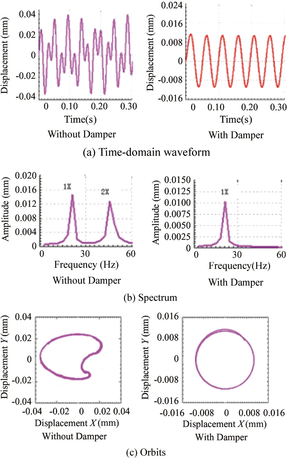
Here the time-domain waveform, amplitude spectrum and axis orbits of node 3 would be analyzed (distant from the bearing at node 2 45mm,seen in Fig.2) for demonstration. Figs.4(a)~4(c) show comparisons between controlled and uncontrolled time-domain waveform, spectrum and axis orbits by shear viscous damping force in the y direction. In Fig.4, 1X and 2X denote frequency of 1 time, 2 times frequency components of the operating speed.

Fig.4 The comparisons of rotor misalignment simulation results with and without damper
The simulated results in Fig.4 clearly show that the time-domain waveform appears beat vibration fluctuations(seen in Fig.4(a)) due to the force of unbalance and misalignment without the control of shear viscous dampers. In addition, apart from the 1X vibration component, the 2X and other multiples vibration components of running speed appear in the frequency spectrum (seen in Fig.4(b)); the orbit presents a “banana” shape due to the misalignment fault . However, comparing the feature after adding dampers, the time-domain waveform of the rotor changes to a stable sine wave; the 2X and other multiples vibration components of running speed almost disappear in the spectrum and also the 1X vibration component is decreased significantly and the axis orbits become stability elliptical orbits.
3 Experimental verification
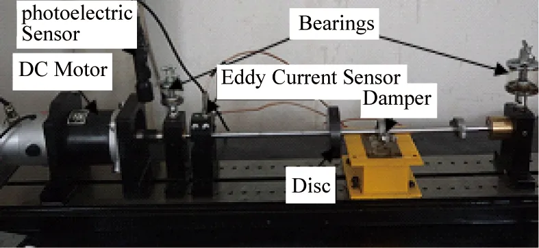
In this section, the theoretical model for misaligned rotor systems in the cases without and with the control of shear viscous dampers is experimentally verified. And a rotor test bench is built up ,shown in Fig.5, whose parameters are consistent with the simulation parameters. The rigid disc is located at the mid -span of the shaft. The rotor is driven by a DC motor, supported by two sliding bearings at both ends of the shaft. There are 16 rotary axial threaded holes in the disc for simulating unbalanced fault. Eddy current sensor is installed on the shaft to measure radial vibration displacement of shaft.

Fig.5 The rotor testing
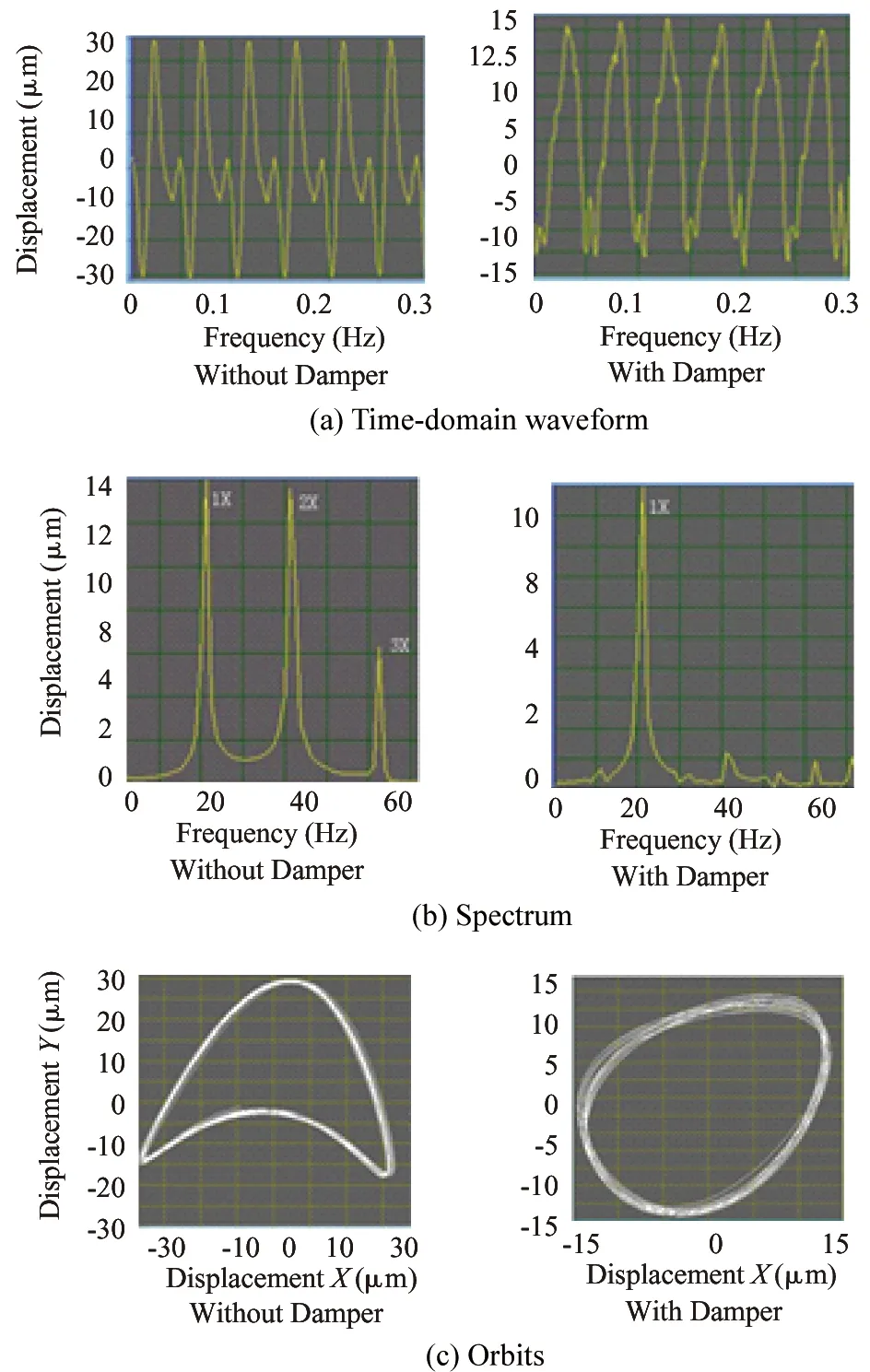
Simulation of angular and parallel misalignments with less than 1 mm positioning error is imposed at the bearing locating near the drive motor, as shown in Fig.6. In the experiments, the domain waveforms ,spectrum and axis orbits of measuring point in the cases without and with the control of shear viscous dampers are obtained by data acquisition system. Here also the running speed 1250r/min is chosen for analysis. The experimental results are shown in Fig.7.

Fig.6 Coupling misalignment test diagram

Fig.7 The comparisons of rotor misalignment experimental results with and without damper (1250r/min)
The experimental results in Fig.7 illustrate that without adding the shear viscous damper, the rotor is obviously in the unbalance and misalignment fault condition: beat vibration fluctuation with M-type appears at the time-domain waveform; apart from the 1X vibration component, the 2X and 3X vibration components of running speed appear in the frequency spectrum; and the orbit presents “banana” shape. These experimental characteristics are consistent with the simulation results in Fig.4. After installing shear viscous damper on the shaft, the time-domain waveform transforms from beat vibration fluctuation condition into regular sine wave, which reduces the magnitude of 35μm to 13.5μm, with a decline of approximately 61%. In the frequency spectrum in Fig.7(b), the 2X ,3X and other multiples vibration components of running speed almost disappeared. And the amplitude of 1X is reduced from 14μm to 9.9μm, with a decline of approximately 30% ; the amplitude of 2X is reduced from 13.6μm to 1.1μm, reduced by 92%. axis trajectory into the banana-shaped oval. This is consistent with the simulation results , which shows that the shear viscous damper can suppress the multiple frequency vibration components of running speed due to misalignment.
4 Conclusion
This paper analyzes a new-type shear viscous damper for vibration suppression effect to misaligned rotor systems. From the simulation and the experimental analyzed results it may be concluded that the new-type shear viscous damper provides control of damping force which significantly reduces the rotor vibration due to unbalance and misalignment in the case of non-stop machine. It could not only reduce the 1X vibration component, but also could eliminate the high multiples frequency vibration components caused by shaft misalignment . And it may enhance stability of the rotor system, which has a certain reference value for the actual project.
[ 1] Song G X, Song J H, Liang H Z, et al. Studies and analysis of high capacity rotary machines with misalignments. Turbing Technology, 2013,55(1):1-5 (In Chinese)
[ 2] Liao M F, Liang Y Y, Wang S J, et al. Misalignment in drive train of wind turbines. Mechanical Science and Technology for Aerospace Engineering, 2011,30(2):173-180 (In Chinese)
[ 3] Wang Y B. Shaft misalignment induced vibration in high capacity steam-turbine generator sets. Power Engineering, 2004,24(6):768-774 (In Chinese)
[ 4] Zhang J H, Ma L, Ma W P, et al. Experiment and dynamic analysis of flexible rotor-ball-bearing system with unbalance rubbing misalignment coupling faults. Journal of Tianjin University, 2012,45(10):854-864 (In Chinese)
[ 5] Lei W P, Han J, Li Z H, et al. Dynamic response analysis of the rotors connected by the misaligned gear coupling. Journal of Mechanical Strength, 2012,34(3):327-332 (In Chinese)
[ 6] Sekhar A S, Prabhu B S. Effects of coupling misalignment on vibrations of rotating machinery. Journal of Sound and Vibration, 1995,185(4):655-671
[ 7] Li M. Analysis of the coupled lateral torsional vibration of a rotor-bearing system with a misaligned gear coupling. Journal of Sound and vibration,2001, 243(2):283-300
[ 8] Li M, Li Z G, Zhang Y B. Non-linear dynamics of unsymmetrical generator rotor systems with parallel misalignment. Proceedings of the CSEE, 2012,32(5):111-118 (In Chinese)
[ 9] Tejas H. Patel, Ashish K. Darpe. Vibration response of misaligned rotors. Journal of Sound and Vibration, 2009,325(3): 609-628
[10] Li X Y. Faults Dynamic Analysis and Recognition of Rotor Misalignment rubbing Coupling:[Ph.D Dissertation]. Nanjing: Nanjing University of Aeronautics and Astronautics, 2009. 1-5 (In Chinese)
[11] Pennacchi P, Vania A, Chatterton S. Nonlinear effects caused by coupling misalignment in rotors equipped with journal bearings. Mechanical Systems and Signal Processing, 2012, 30:306-322
[12] Sudhakar,G.N.D.S,Sekhar. Coupling misalignment in rotating machines modeling effects and monitoring. Noise & Vibration Worldwide, 2009, 40(1): 17-39
[13] Wan Z, Jing J P, Meng G, et al. Nonlinear dynamic behaviors and stability of a rotor-bearing system with flexible coupling misalignment. Journal of Vibration and Shoch, 2012,31(24):20-25 (In Chinese)
[14] Wang L, Gu Y J. Study on on-line diagnosis method of coupling parallel misalignment for turbo-generator. Modem Electric Power, 2011, 28(3): 70-74 (In Chinese)
[15] Shen D Y. Misalignment fault diagnosis. Condition Monitoring and Diagnostics Technology, 2010,4:52-53 (In Chinese)
[16] Wang Z. Diagnosis and analysis of bad alignment fault. China Plant Enineering, 2003,(12):40-41 (In Chinese)
[17] Wang D W, Zhang J W. Alignment trouble analysis and diagnostic skill. Plant Maintenance Engineering, 2005,(10):29-31 (In Chinese)
[18] Wang W G, Zhao J R, Yan T H, et,al. A new bearing adjustive device for elevation and lateral. China Patent: No.201220016574.4,2012-08-22 (In Chinese)
[19] Li H M, Zeng S, Wang X X. On-line compensation system of rotor misalignment based on auxillury magnetic bearing. Chinese Journal of Mechanical Engineering, 2005,41(9):150-154 (In Chinese)
[20] Li H M, Zeng S, Wang X X. The experimental study of the on line elimination of rotor misalignment using auxiliary electromagnetic bearing. Machine Tool & Hydraulics, 2004,12:102-103 (In Chinese)
[21] Zhang G Q. Cable-stayed bridge - Polymeric Materials Using Passive Damping System[Ph.D Dissertation]. Harbin: Harbin Institute of Technology, 2011 (In Chinese)
[22] Zheng Wanshan. Designed method and engineering application of viscous shear damper[Ph.D Dissertation]. Xi’an: Chang’an University. 2002 (In Chinese)
[23] Nicos Makris1 and M. C. CONSTRANTINOU FRACTIONAL-DERIVATIVE MAXWELL MODEL FOR Viscous DAMPERS . J. Struct. Eng. 1991.117:2708-2724
[24] Han Q K,Yu T, Wang D W, et al. Nonlinear Vibration Analysis and Diagnosis Method of Fault Rotor System. Beijing: Science Press, 2010. 67-88 (In Chinese)
Huang Xiujin, born in 1989. She received her B.S. from Beijing University of Chemical Technology in 2012 and currently is a master of Beijing University of Chemical Technology. Her research interests is rotating machinery vibration reduction.
10.3772/j.issn.1006-6748.2015.02.018
①Supported by the National Basic Research Program of China (No. 2012CB026000) and the Joint Project Special Fund of Education Committee of Beijing and the Ph.D. Programs Foundation of Ministry of Education of China (No. 20110010110009).
②To whom correspondence should be addressed. E-mail: he63@263.net Received on Feb. 18, 2014, Wang Cai
杂志排行
High Technology Letters的其它文章
- Improving wavelet reconstruction algorithm to achieve comprehensive application of thermal infrared remote sensing data from TM and MODIS①
- Security analysis of access control model in hybrid cloud based on security entropy①
- Multi-sensor federated unscented Kalman filtering algorithm in intermittent observations①
- MPLPK: A mobile path localization protocol based on key nodes①
- Design and development of real-time query platform for big data based on hadoop①
- A method for retrieving soil moisture from GNSS-Rby using experiment data①
