Novel Method of Evaluation of Carter Factor for Closed Slot Submersible Motor Including Fringing Effect and Magnetic Saturation
2015-04-14
(Hefei University of Technology Hefei 230009 China)
Novel Method of Evaluation of Carter Factor for Closed Slot Submersible Motor Including Fringing Effect and Magnetic Saturation
Bao Xiaohua Liang Na Fang Yong Li Fuying
(Hefei University of Technology Hefei 230009 China)
This paper deals with a new method called equivalent open slot method for calculating the Carter Factor of closed slot submersible motors. Two analytical methods including conventional method and improved method were introduced to calculate the Carter Factor and the results are compared with the finite element method to find a proper analytical method for open slot machine. Then we first proposed that the closed slots can be replaced by open slots because the flux density in the slot bridge is highly saturated. Permeability ratio method and geometric method are introduced to calculate the Carter Factor by considering the fringing effect and the magnetic saturation of the slot bridge. Models with different closed slot types are constructed and finite element computations in turn validated the equivalent open slot method including permeability method and geometric method.
Equivalent open slot method, Carter Factor, finite element method(FEM), fringing effect, magnetic saturation
1 Introduction
Recently, electrical submersible pump (ESP) becomes an economic alternative for producing liquid from oil and water wells. Due to the special operation environment, some ESP motors are equipped with both closed slot stator and closed slot rotor for the purpose of water friction loss reduction[1].
F.W. Carter was the first to propose the equivalent air gap to consider the slotting effect[2]. The equivalent air gap is equal to the physical air gap multiplied by the so-called Carter Factor and this concept has been well accepted by most designers of rotating machine. The Carter Factor can be calculated by analytical method and finite element method[3,4]. Though finite element method can give accurate results considering saturation and nonlinearity of magnetic materials[5], this method is time consuming and poorly flexible for the first step of design state of electrical machines[6]. The accuracy of analytical methods based on conformal mapping is limited because it is assumed that the slot height is infinite[7]. Many papers studied the Carter Factor and the air gap magnetic field by using conformal transformations[8,9]. Single slot models and multiple slot models have been introduced to analyze the magnetic field as well as Carter Factor[8-10].
Recently, many authors concentrated on the slotting effect on the performance of the electrical machines. Hung Vu Xuan studied the influence of stator slotting on performance of the permanent magnet machines, such as the distribution of air gap magnetic field, the flux linkage, the internal voltage, the mean torque and the iron losses[4]. Daisuke Hiramatsu proposed a new calculation method considering the effects of multiple slots and eddy current reaction induced on the surface of the rotor poles[11]. According to the method, the slot ripple losses induced on the rotor surface has been estimated. J.T. Chen investigated the significant inf-luence of slot opening on optimal stator and rotor pole combination and electromagnetic performance of switched-flux permanent magnet brushless machines[12]. Gurakuq Dajaku dealt with a new analytical method for studying the stator slotting effect on the magnetic field distribution[13]. However, few focused on the induction machine or submersible motor, and nobody gave a full presentation of evaluation method of Carter Factor for closed slot motor.
The Carter Factor is generally assumed to be 1 according to the computation expressions of Carter Factor. However, this may result in major errors especially for closed slot machine whose slot bridge is narrow and long. Due to the thin slot bridge, the flux density in the slot bridge is highly saturated. As a result, the flux density is not uniform and the Carter Factor is no longer equal to 1.
In this paper, a new method of evaluation of Carter Factor for closed slot submersible motor is proposed. The Carter Factor expressions of conventional method and improved method were evaluated by comparing the results to FEM computations to find the suitable expression. Based on the improved method, the equivalent-open-slot methods including permeability ratio method and geometric method were introduced to calculate the Carter Factor for closed slot machine. Finally, the finite element analysis of the closed slot machine with different slot types was carried out to validate the proposed method.
2 Evaluation of Carter Factor Expressions for Open Slot Machine
2.1Conventional Method of Calculating Carter Factor
Generally, the surfaces of both the stator and the rotor are split with slots. The flux density always decreases at the slot opening, and therefore it is difficult to determine the flux density distribution of the slot pitch between the stator and the rotor[5].
However, the effective air gap length gesinstead of the physical air gap length g was proposed by F.W. Carter to consider the slotting effect. By assuming the rotor to be smooth, the effective length is determined by using Carter Factor Kcsas

By assuming the slot is infinitely deep, the authors used conformal transformations to calculate the Carter Factor and the magnetic field[8,9]. Then the Carter Factor can be expressed as

where tsis the stator slot pitch, and b0is stator slot opening.
When both the stator and the rotor surface are split with slots, we first calculate Kcsby assuming the rotor surface to be smooth. Then calculations are repeated by assuming the stator surface to be smooth and the total Carter Factor can be written as[4,5]

or

2.2Improved Method of Calculating Carter Factor
The Carter Factor is also the ratio of the maximum flux density Bg,maxto the average flux density Bg, as shown in Fig.1. The figure shows the distribution of the magnetic flux density along a slot pitch. The flux densities distributed from point A to B and from point F to G are close to the maximum flux density. Inaddition, the minimum flux density corresponding to point D locates at the slot center. The average flux density can be obtained by the flux density distribution and the Carter Factor can be expressed as

Fig.1 Distribution of the magnetic flux density along a slot pitch

The variation of the flux density assuming no eddy currents damping the flux variation can be expressed as[11]


In order to take the fringing effect into consideration, B. Heller and V. Hamata proposed an analytical expression to describe the flux density distribution in the case of an air gap slotted on only one side[14]. The analytical expression is suitable for slots with b0/ts<0.625. They believed that the farthest point of the slotting effect is about 0.8b0. If the origin is set at the centre of the slot, the expressions can be written as[14]


and Here α0=2b0/D andαd=2π/Qs=2ts/D, where D denotes the inner diameter of the stator. Then the average flux density can be calculated by

Hence, an improved formula of calculating Carter Factor is

2.3Finite Element Analysis of Calculating Carter Factor
Carter Factor can also be calculated by a static FEM computation at a single rotor position for an open slot or closed slot machine. Master and slave boundary conditions were applied and reasonable meshes were generated, as shown in Fig.2b. The radial flux density under a stator slot along one slot pitch can be obtained by the radial flux density along the middle gap line, as shown in Fig.2a. Four different slot openings in Fig.3 are 12mm, 14mm, 16mm and 18mm, respectively. It can be seen from Fig.3 that the minimum flux density located at the middle of the slot opening, while the maximum flux density located at the teeth. In addition, drops in the flux density caused by stator slots with large slot openings are bigger than those with small slot openings.

Fig.2 Static FEM computation at a single rotor position for an open slot
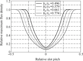
Fig.3 Flux densities along a slot pitch with different slot openings
The calculation results of the Carter Factor obtained by the conventional method, improved method and finite element method are shown in Fig.4. It can be seen from Fig.4 that the results obtained by the conventional method are consistent with the improvedmethod. The results obtained by the finite element method are in good agreement with the results obtained by the conventional method and improved method when the slot opening is small. However, the results obtained by the finite element method are larger than the results obtained by the conventional method and improved method when the slot opening is large. It should be pointed out that error of the results obtained by the improved method and finite element method reaches more than 10% when the slot opening (namely slot width of semi open slot) is larger than 12mm. When the slot width is 16mm, the error is about 15%. The improved method will be used to calculate the Carter Factor of the closed slot machine in latter section.
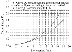
Fig.4 Calculation results of the Carter Factor for open slot
3 Equivalent-Open-Slot Method of Carter Factor for Closed Slot Machine
3.1Permeability Ratio Method
When closed slot is adopted in the stator, the Carter Factor is generally assumed to be 1 according to the computation expressions of Carter Factor. However, this may result in major errors especially for closed slot machine whose slot bridge is narrow and long. Due to the thin slot bridge, the flux density in the slot bridge is highly saturated. As a result, the flux density is not uniform and the Carter Factor is no longer equal to 1.
In this paper, a new method is proposed called permeability ratio method for calculating the Carter Factor of closed slot machine with different stator slots, as shown in Fig.5. Three open slot types are modeled for finite element analysis in latter section. Due to the high saturated slot bridge, the magnetic resistance of the slot bridge cannot be ignored. Hence, the closed slot machine could be equivalent to an open slot machine.
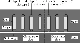
Fig.5 Different stator slot types
The computational formula of the equivalent slot opening could be expressed as

Where ksis a shape coefficient, khis a coefficient associated with slot bridge height and air gap length, kuis a uniform saturated coefficient, μ0is the vacuum permeability, μ1is the permeability of the slot bridge, and bsis the slot width.
According to the motor design experience, the uniform saturated coefficient is adopted 0.6. In this paper, the shape coefficients of the models of the four closed slot types, as shown in Fig.5, are 1, 0.86, 0.39 and 0.63, respectively. In addition, the ratio of the vacuum permeability and the permeability of the slot bridge can be obtained by the polynomial fit of the permeability curve when the magnetic flux density is larger than 1.8 T, as shown in Fig.6.

Fig.6 Magnetic field strength and permeability of silicon steel
Hence, the Carter Factor of the closed slot machine can be calculated by the improved method. The results are shown in Fig.7. It can be concluded that the slot type1 has the largest Carter Factor at a certain slot bridge height. In addition, the Carter Factor from large to small in turn is slot type 1, slot type 2, slot type 4 and slot type 3. Moreover, the Carter Factors of different slot types decrease with the increasing slot bridge height.
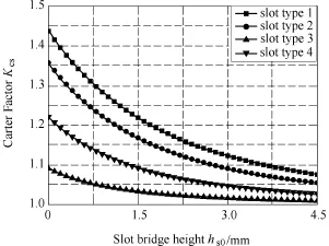
Fig.7 Calculation results of Carter Factor of the closed slot machine by using permeability ratio method
3.2Geometric Method
There is another method of calculating Carter Factor of closed slot machine, as we called geometric method. The geometric method can be used for engineering calculation but the method has a limitation because it is not easy to understand. The equivalent slot opening can be obtained by auxiliary lines, as shown in Fig.8. The inclined angle of the auxiliary line is α, and α is adopted 45° in this paper. The slot width is 16.2mm, as shown in Tab. . The computational formulas of the equivalent slot openings corresponding to the four slot types can be expressed as

Where bsthe slot width; R1is the radius of the 1/4 arc in slot type 2.

Fig.8 Sketch of geometric method of four stator slot types
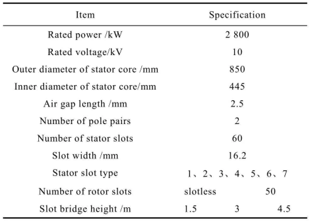
Tab. Main specifications of analysis model
The calculation results of the Carter Factor obtained by the geometric method are shown in Fig.9. It can be seen from Fig.9 that the main trend of the Carter Factor distribution is similar with that of the Carter Factor distribution obtained by the permeability ratio method. However, the Carter Factors of the slot type 3 and slot type 4 are almost close to 1 when the slot bridge height is larger than 3mm.
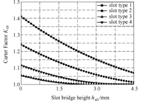
Fig.9 Calculation results of Carter Factor of the closed slot machine by using geometric method
4 Finite Element Analysis of Carter Factor for Closed Slot Machine
In order to take the multiple-slot effect into con-sideration, transient FEM models with all stator slots including rotor motion were constructed, as shown in Fig.10. Fig.10 shows the model with a slotless rotor and with a slot bridge height of 1.5mm. The main specifications of the analysis model were shown in Table. I. Seven stator slot types including four closed slot types and three open slot types were analyzed, as shown in Fig.5. The slot openings of the three open slot types are 1mm (small-open), 8.1mm (semi-open) and 16.2mm (full-open), respectively.

Fig.10 FEM model and magnetic field
In this paper, the flux density is obtained under a slot pitch at the center line of the pole for calculating Carter Factor. The results can be used for validating the analytical methods. The flux density distributions of the models with different slot types are shown in Fig.11, and the calculation results of Carter Factor are shown in Fig.12.
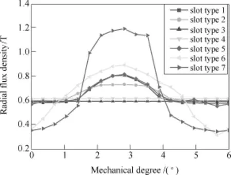
Fig.11 Radial flux density along a slot pitch

Fig.12 Calculation results of Carter Factor
It can be seen from Fig.12 that the slot bridge height has a significant impact on Carter Factor especially for models with slottype1 and slot type 2. The Carter Factor of the model with slot type1 is the largest among those of the models with closed slot types. The Carter Factor of the model with slot type 3 is similar to the Carter Factor of the model with slot type 4. The Carter Factors of the models with closed type slots are close to 1 when the slot bridge height goes up to some extent. Moreover, the slot bridge height has little impact on the Carter Factor of the model with semi-open slot but has a great impact on the Carter Factor of the model with small-open slot.
In this paper, the calculation results of Carter Factor obtained by finite element method can be used to validate the permeability ratio method and the geometric method. The calculation errors are shown in Fig.13. It can be seen from the results that the maximum error is 13.6% and the minimum error is 0.02%. The errors of the geometric method are smaller than the errors of the permeability method as a whole. According to the previous analysis, when the slot width of an open slot is 16mm, the error is about 15%. It should be emphasized that the errors of the both two methods are much smaller than 15%. The error of the geometric method is smaller and the error of the permeability method is in the acceptable range.
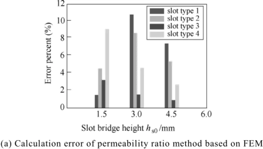

Fig.13 Calculation errors
In fact, the flow direction of the current in stator coil has an impact on the behavior of the air gap density along a slot pitch[5]. Hence, the results obtained by the flux density under a slot pitch at the center line of the pole are accurate enough for validating the analytical methods but are meaningless for the further consideration of the multiple-slot effect especially for the consideration of the full-model machine.
In this paper, the Carter Factors within a pole pitch for comparison are calculated. The flux density distributions of the models with different slot types are shown in Fig.14. It can be seen from the curves that the flux density distribution curves of the models with slot type 3 and slot type 4 are smoother than the others. The curves of the models with open slot types are rough due to the slotting effect.

Fig.14 Radial flux density distributions of the models with different slot types
The distributions of the Carter Factor of the different slot types are shown in Fig.15. The results are in accordance with the flux density distribution curves since the rough curve of a slot type means the slot type has a larger Carter Factor. Then the average value can be obtained by the distributions of the Carter Factor along a pole pitch. And the average Carter Factors are shown in Fig.16. The results obtained from the pole pitch are in accordance with the results obtained from the slot pitch of the pole center line as a whole.

Fig.15 Distributions of the Carter Factor of the different slot types

Fig.16 Average Carter Factors of different slot types
5 Conclusion
In this paper, a new method of Carter Factor evaluation for closed slot submersible motor is proposed. It was found that for single slot model, conventional method and improved method are in good agreement, but the finite element method is consistent with analytical methods (including conventional method and improved method) only when the slot opening is small. In addition, when the slot opening (namely slot width in full open slot) is 16mm, the error is about 15%. Equivalent open slot method is put forward including permeability ratio method and geometric method to calculate the Carter Factor. The results show that the maximum error is 13.6% and the minimum error is 0.02%. In addition, the error of the geometric method is smaller and the both errors of the geometric method and permeability method are in the acceptable range.
Reference
[1] Fang Yong, Bao Xiaohua, Lü Qiang, et al. Analysis of electromagnetic force distribution on end winding of electrical submersible motor during starting transient operation[J]. IEEE Transactions on Magnetics, 2013, 49(10): 5341-5345.
[2] Carter F W. Note on air gap and interpolar induction [J]. Journal of Institution of Electrical Engineering, 1926, 29(146): 923-933.
[3] Damir Zarko, Drago Ban, Thomas A Lipo. Analytical calculation of magnetic field distribution in the slotted air gap of a surface permanent-magnet motor using complex relative air gap permeance[J]. IEEE Transactions on Magnetics, 2006, 42(7): 1828-1837.
[4] Hung Vu Xuan, Domenico Lahaye, Henk Polinder, et al. Influence of stator slotting on the performance of permagnet machines with concentrated windings[J]. IEEE Transactions on Magnetics, 2013, 49(2): 929-938.
[5] Juha Pyrhonen, Tapani Jokinen, Valeria Hrabovcova. Design of rotating machines[M]. John Wiley & Sons, 2008.
[6] Thierry Lubin, Smail Mezani, Abderrezak Rezzoug. Exact analytical method for magnetic field computation in the air gap of cylindrical electrical machines considering slotting effect[J]. IEEE Transactions on Magnetics, 2010, 46(4): 1092-1099.
[7] Zhu Z Q, Howe D. Instantaneous magnetic field distribution in brushless permanent magnet dc motors, Part Ⅲ: Effect of stator slotting[J]. IEEE Transactions on Magnetics, 1993, 29(1): 143-151.
[8] Carter F W. The magnetic field of the dynamoelectric machine[J]. Journal of Institution of Electrical Engineering, 1926, 64(359): 1115-1138.
[9] Kamel Boughrara, Rachid Ibtiouen, Damir Zarko, et al. Magnetic field analysis of external rotor permanentmagnet synchronous motors using conformal mapping [J]. IEEE Transactions on Magnetics, 2010, 46(9):3684-3693.
[10] Neville S, Sc B, D I C. Use of Carter’s coefficient with narrow teeth[J]. Proceedings of Institution of Electrical Engineering, 1967, 114(9): 1245-1250.
[11] Daisuke Hiramatsu, Tadashi Tokumasu, Masafumi Fujita, et al. A study of rotor surface losses in smallto medium cylindrical synchronous machine[J]. IEEE Transactions on Energy Conversion, 2012, 27(4):813-821.
[12] J T Chen, Z Q Zhu, S Iwasaki, et al. Influence of slot opening on optimal stator and rotor pole combination and electromagnetic performance of switched-flux PM brushless AC machines[J]. IEEE Transactions on Industry Application, 2011, 47(4): 1681-1691.
[13] Gurakuq Dajaku, Dieter Gerling. Stator slotting effect on the magnetic field distribution of salient pole synchronous permanent-magnet machines[J]. IEEE Transactions on Magnetics, 2010, 46(9): 3676-3683.
[14] B Heller, V Hamata. Harmonic field effects in induction machines[M]. Amsterdam: Elsevier Scientific, 1977.
Brief notes
Bao Xiaohua male, was born in 1972, professor,his main research interests are in the field of motor design, magnetic field analysis, and finite element analysis.
Liang Na female,was born in 1993, a postgraduate,her main research interests are in the field of motor design, magnetic field analysis.
考虑边缘效应和磁饱和影响的闭口槽潜水电机卡特系数计算新方法
鲍晓华 梁 娜 方 勇 李福英
(合肥工业大学电气与自动化工程学院 合肥 230009)
针对闭口槽潜水电机卡特系数的计算提出了一种等效开口槽的新方法。分析卡特系数计算的两种解析法,包括传统解析法和改进解析法,并将解析法计算结果与有限元法计算结果进行对比,以寻求适合开口槽电机卡特系数的最优方法。由于槽磁桥高度饱和,本文首次提出用开口槽等效闭口槽的卡特系数计算新思路,在考虑边缘效应和磁饱和影响下,采用磁导等效法和几何等效法对不同闭口槽型电机模型的卡特系数进行了等效计算,并采用有限元法对等效开口槽法的结果进行了验证。
等效开口槽法 卡特系数 有限元法 边缘效应 磁饱和
TM35
This work was supported by the National Natural Science Funds of China under Grant (51177033、51377039), Fundamental Research Funds for the Central Universities(2012HGZY0003), and Hefei Hengda Jianghai Pump Co, Ltd.
Received March 26, 2014, revisied April 26, 2014.
