A new test generation algorithm fornon- robust path delay faults
2015-03-09YingZHAOieqiuZHAO
Ying ZHAO,X ie-qiu ZHAO *
,Yan-juan LI2
(1 Electrical& Information Engineering College,Beihua University,Jilin 132021,China)
(2 College of Information and Computer Engineering,Northeast Forestry University,Harbin 150040,China)
A new test generation algorithm fornon- robust path delay faults
Ying ZHAO1,X ie-qiu ZHAO1*
,Yan-juan LI2
(1Electrical& Information Engineering College,Beihua University,Jilin 132021,China)
(2College of Information and Computer Engineering,Northeast Forestry University,Harbin 150040,China)
A new test generation algorithm based on neural network and artificial bee colony optimization for nonrobust path delay faults is proposed in this paper because the traditional test generation algorithm’s efficiency is low.The algorithm switches digital circuit into equivalent partial leaf-dag circuit firstly and then constructs the constraint circuit for the equivalent circuit.Hopfield neural networkmodel is constructed for the constraint circuit and energy function is obtained.The test vector for the single stuck-at fault of equivalent circuit can be obtained by using artificial bee colony optimization algorithm to solve theminimum of energy function,then the test vector is changed to the test vector pairs for the non-robust path delay fault of original digital circuit.The experiment results demonstrate that the algorithm’s fault coverage algorithm can achieve 98%,average test generation time is less than 0.8 seconds.
Test generation,Non-robust path delay fault,Hopfield neural network,Artificial bee colony
Ying ZHAO,Ph.D.,E-mail:731856651@qq.com
*Corresponding author:Xie-qiu ZHAO,Associate Professor.
E-mail:297744@qq.com
1 In troduction
There are a lotof path delay faults in the digital circuit, especially the non-robust path delay faults.When the non-robust path delay faults lie in the digital circuit,the circuit can’twork normally,and sometimesmay paralyze completely[1].The test generation algorithm for non-robust path delay faults is to find test vector pairs so that the faults can be find at the output of the circuit.Many researchers studied and proposed a lot of algorithms.S.ohtake proposed a method of test generation for path delay faults using stuck-at fault test generation algorithm[2],the algorithm’s faults coverage can reach 91%,but the average test generation time is long;Hiroshi Takahashi proposed an alternative method of generation tests for path delay faults using Ni-detection test sets[3],the algorithm’s average test generation time is short,but faults coverage is low and the test set is large.The algorithm proposed in this paper switches digital circuit into equivalent partial leaf-dag circuit,then the test vector for the single stuck-at fault of equivalent circuit can be obtained by using Hopfield neural network and artificial bee colony optimization algorithm.The test vector pairs for the non-robust path delay fault of original digital circuit can be obtained by corresponding relation.
2 The corresponding know ledge about non-robust path delay fau lt
Defination 1:A path of a digital circuit composes by a series of gate{G1,G2,…,Gn}and the input lines,the output lines.G1is the first gate and Gnis the last gate,the output of Giis the input of Gi+1.
Defination 2:When the input of the path P has jumping change,the output of the path P also has jumping change,when the jumping time exceeds specified limit,the path P has the path delay fault,rising edge and falling edge path delay fault can be represented by P↑ and P↓.
Defination 3:When the path P of the digital circuit has path delay fault and other input values of all gates on the path are non-control value(the non-control value of AND gate and NAND gate is 1,the non-control value of OR gate and NOR gate is0),the fault is called non-robust path delay fault.
For the digital circuit in Fig.1,cG2G4G5y is a path P,if the inputb of gate G2is1,the input f of gate G4is 0,the input g of gate G5is 0,the fault is non-robust path delay fault if path P has path delay fault.
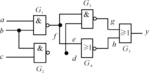
Fig.1 A digital circuit
3 Equivalent sw itching of digital circuit
In order to switch non-robust path delay fault to equivalent single stuck-at fault,the digital circuit should be switched to its equivalent leaf-dag circuit.The following is themethod:
1)Move all inverters on the path P to inputs of gates according to De Morgan’s laws.

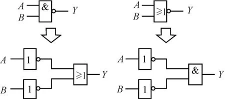
Fig.2 Equivalent circuit o f NAND gate and NOR
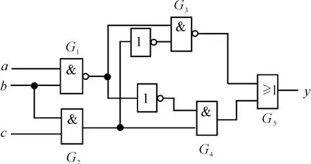
Fig.3 Equivalent circuit o fm oving the inverter on path cG2 G4 G5 y o f Fig.1 to input
2)Move all fanouts of gates on the path P to inputs of gates.
For Fig.1,gate G2has two fanouts d and e,gate should be duplicated in order to move fanouts to inputs.G2was duplicated to two gates,the switching circuit is shown in Fig.4 according themethod.
It can be proved stuck-at0(stuck-at1)fault of input c in Fig.4 corresponds with rising edge(falling edge)delay fault of cG2G4G5y in Fig.1.For the circuit of Fig.1,if path cG2G4G5y has rising edge delay fault,when the test vector pair(000,001)are given to the input,the fault can be detected at the circuit.For Fig.1,the inputs abc change from 000 to001,the output is 0 at t1if the circuit has fault and the output is 1 at t1if the circuit doesn't have the fault(Fig.5).For Fig.4,when input c has stuck-at 0 fault,when the test vector 001 is given to the input,the output is 1 if the circuit hasn’t fault,and the output is0 if the circuit has fault.So the test results of the non-robust path delay fault of Fig.1 and the stuck-at 0 fault of Fig.4 are same.So the test generation of non-robust path delay fault can be changed to the test generation of stuck-at fault of equivalent leaf-dag circuit.
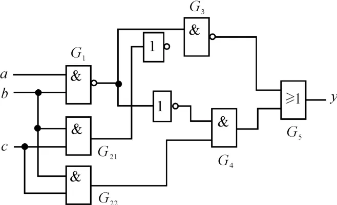
Fig.4 Equivalent circuit o fm oving all fanouts on path cG2 G4 G5 y o f Fig.1 to inpu t
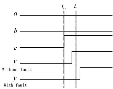
Fig.5 Test resu lts
4 Neural network model’s construction for single stuck-at fault of equivalent circuit
Hopfield neural network model[4]is constructed for single stuck-at fault of equivalent circuit.Hopfield neural network’s energy function is defined by the for-mula:

Where Tijis the weight associated with the link between neurons i and j,Viis the state value of neuron i,Iiis the internal parameter of neuron i,K is a constant and N is the number of neurons in the neural networks.The activated values of neurons are 0,1,Tij=Tjiand Tii=0.
We can obtain the neural network model of the basic gate circuit according to reference[4],the digital circuits are composed of basic gates,so the digital circuit’s neural networkmodel also can be obtained conveniently and the energy function can also be obtained[5].
Consistent states are the states that satisfy the circuit’s function;other states that don’t satisfy the circuit’s function are called inconsistent states.When the neuron states are consistent with the function of the circuit[6],the energy function has globalminimum value.In this paper,the energy function’s value is 0 for all consistent states and energy function’s value >0 for all inconsistent states.
In order to obtain the circuitwith consistent states,the constraint circuit[7]should be constructed.The constraint circuits for single-output circuit and m outputs circuit are shown in Fig.6 and Fig.7.
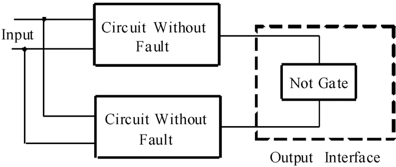
Fig.6 Constraint netw orks for sing le-output circuit
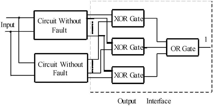
Fig.7 Constraint netw orks for m-output circuit
The test vectors are consistent states for the constraint network and the energy function of the constraint network is0 at that time[8].In thisway,digital circuit test generation problem can be changed to find theminimum value of energy function of the constraint network.
5 A lgorithm realization
Artificial bee colony[9]was proposed by Turkey researcher karaboga in 2005,it is a bionic optimization algorithm of simulating bee to find the best food source.The algorithm haslocal and global search in each iteration,so it can reduce the probability of going into the local optimal solution.When using artificial colony algorithm to solve the optimization problem,the location of the food source was abstracted as the optimal solution,the fitness function value of optimization question determines the quality of the food source.Artificial bees mainly include the employed bees,onlookers and scout bees.Assuming that the algorithm have N initial population[xi](i=1,2,…,n),[xi]hasm variables(m is the number of circuit input),every variable’s value may 0 or 1.The employed bee has neighborhood search for one food source randomly,and updating food source’s location according to formula(2)[10].
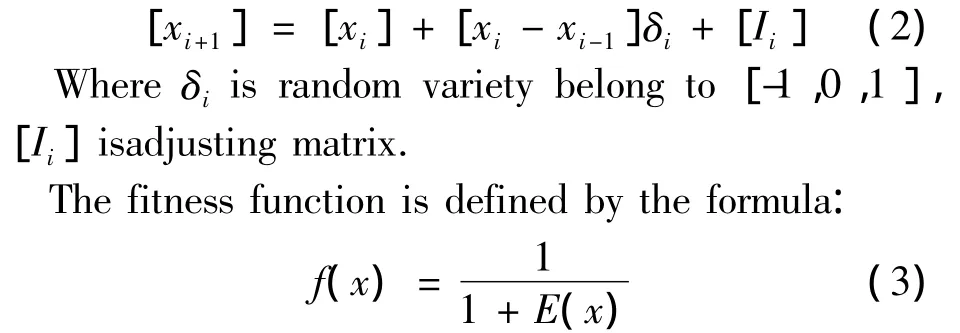
Where E(x)is energy function of constraint network,the value of f(x)belongs to[0,1].If fitness function value f(xi)of food source xiis greater,the performance of xiis better.
When f(xi)is 1,[xi]is a test vector for given single stuck-at fault.When all employed bees have finished searching,they can convey information to the onlookers by means of wagging dance.The onlookers select food source according to the roulette rules,and keep the food source with best return.
In the control algorithm,setting search control parameter as L,it is upper limit that food source has not been updated.If a food source has not been updated after L times search,the food source has gone into local optimum,the food source should be abandoned,the corresponding employed bee is changed to scout bee,a new food source should be generated according to formula(3)[11] instead of the original food source.

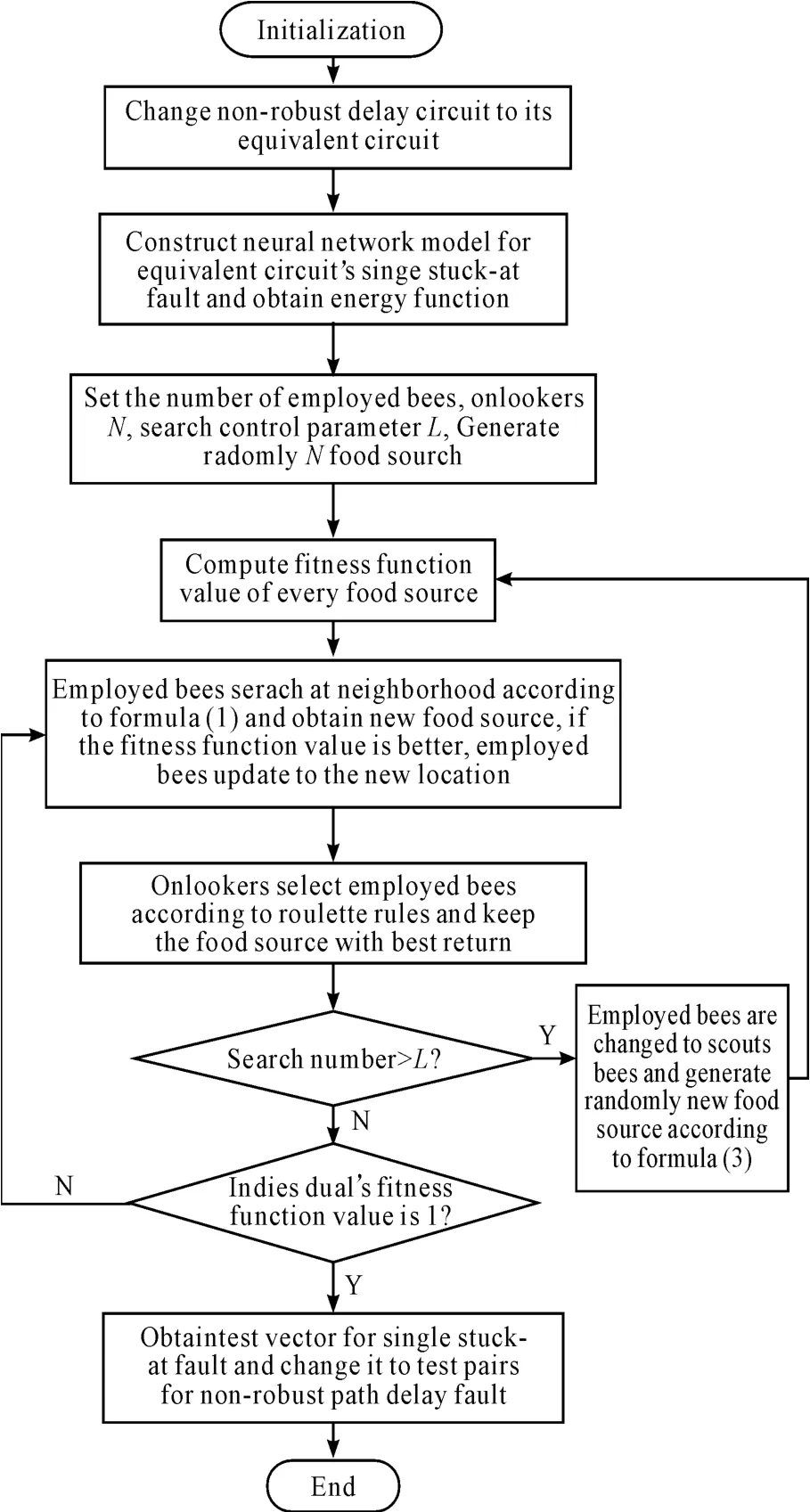
Fig.8 Algorithm flow chart
6 Experim ent resu lt
ISCAS’85 benchmark circuits are international test circuits for test generation algorithm,themerits of the algorithm should be test at the circuits.C17 circuit of ISCAS’85 is shown in Fig.9,the circuithas5 inputs,2 outputs,made up of 6 NAND gates.According to the algorithm in this paper,the test experiment results on C17 are shown in Table 1,the experiment results comparing with other algorithm are shown in Table 2.The experiment results show that the fault coverage increases significantly and the average test generation time is shorter,so the algorithm is better than other algorithms.
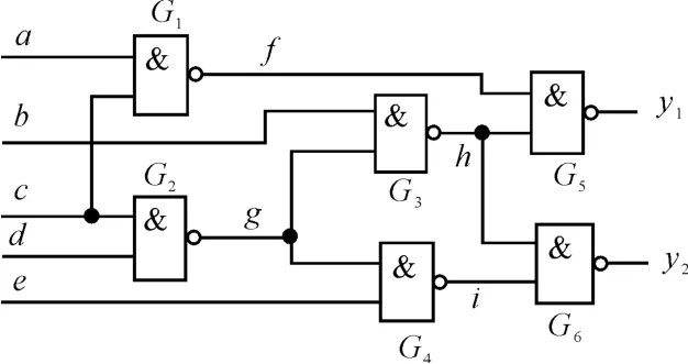
Fig.9 Circuit C17 o f ISCAS’85
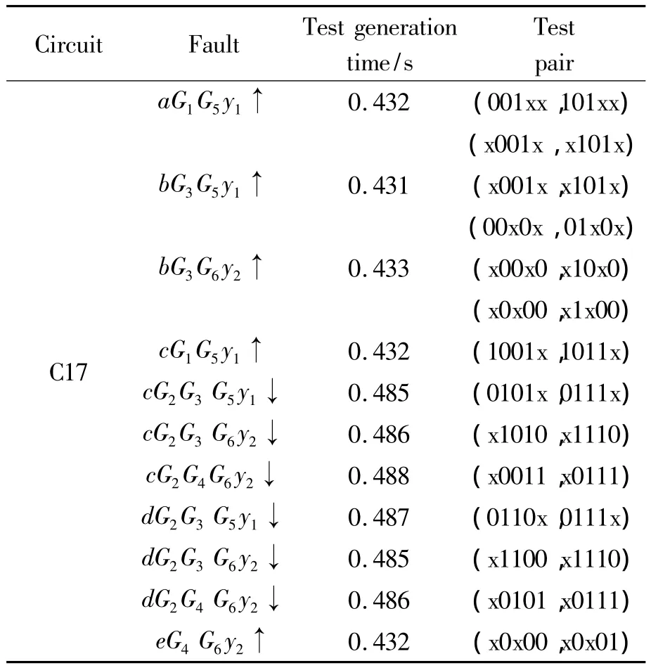
Tab le 1 Experim ent resu lts o f circuit C17
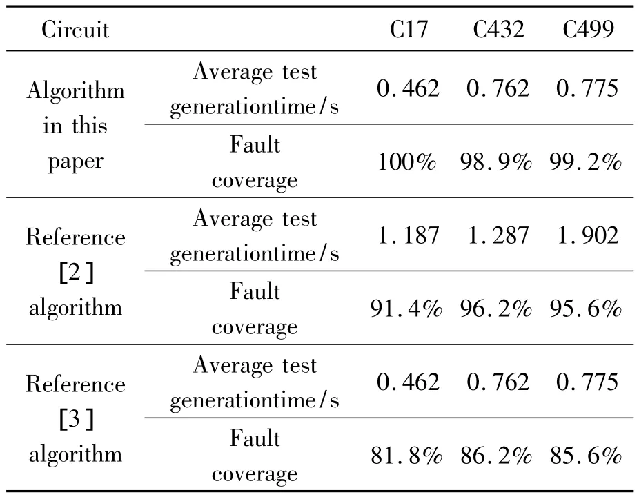
Tab le 2 Test expe rim en t resu lts o f d iffe ren t a lgorithm s
7 Conclusions
In this paper,neural network and artificial colony algorithm are applied to test generation for non-robust path delay fault of digital circuit,neural network and artificial colony algorithm’s advantages aremade full use of and avoiding going into local optimal solution.The experiment results show that the fault coverage algorithm in this paper can achieve 98%,average test generation time is less than 0.8 seconds,the algorithm has obvious advantages comparing with other literature algorithm.But when the algorithm is applied to large-scale sequential logic circuit,there will be a large number of iterations,as well as disadvantages such as low fault coverage and long test generation time,so the algorithm is not suitable for largescale sequential logic circuit.
Acknow ledgem en ts
This work was supported by the National Natural Science Foundation of China(Study on higher-order logic based inductive logic programming learning algorithm and its application,61300098)and Jilin City Technology Bureau Foundation(Intelligent control system ofWarehousing Logistics,201414006).
[1]Smith G L.Model for delay faults upon paths[C]//Int.Test Conference,1985:342-345.
[2]Ohtake S,Ohtani K,Fujiwara H.A method of test generation for path delay faults using stuck-at fault test generation al gorithms[C]//Proceeding design,automation and test in Europe,2003:310-315.
[3]Takahashi H,Kewal K S,Takamatsu Y.An Alternative Method ofGenerating Tests for Path Delay Faults Using Ni-Detection Test sets[C]//Proceedings of the2002 Pacific Rim International Symposium on Dependable Computing,2002:23-24.
[4]Chakrdhar T,Bushnell M L,Agrawal V D.Toward Massively Parallel Automatic Test Generation[J].IEEE Trans.Computer_Aided Design,1999(9):981 -993.
[5]Xue Jian Bin,Li Zhi.The Application of Neural Networks in the Simulation-based Test Generation Algorithm for Hybrid Circuits[J].Journal of Circuits and Systems,2001,6(4):109-110.
[6]Wu lihua,Wang xudong.Three-valued neural network test generation algorithm forMulti-faults based on genetic optimization[J].Chinese Journal of Scientific Instrument,2010,31(8):1744-1749.
[7]Chen zhaoyang,Dingmingyue.A robust algorithm for test generation based on neural network[J].Journal of Huazhong university of science and technology,1999,27(9):90 -91.
[8]Liu xiaodong,Sun shenghe.Neural networks based test generation algorithm for combinational logic circuits[J].Journal of Harbin institute of technology,2002,34(2):256 -257.
[9]Karaboga D.An idea based on honey bee swarm for numerical optimization[D].Kayseri:Erciyes University,2005:35-45.
[10]Elkhateeb N A,Badr R I.Employing artificial bee colony with dynamic inertia weight for optimal tuning of PID controller[J].ICMIC2013,2013,9:42-45.
[11]Dixit G P,Dubey H M.A rtificial bee colony optimization for combined economic load and emission dispatch[J].SEISCON,2011,7:340-342.
非鲁棒路径时滞故障测试生成算法
赵 莹1,赵谢秋1*,李艳娟2
1.北华大学电气信息工程学院,吉林 132021
2.东北林业大学信息与计算机工程学院,哈尔滨 150040
针对数字电路中非鲁棒路径时滞故障测试时间长、故障覆盖率较低的问题,提出了人工蜂群优化的测试生成算法。该算法首先应用电路转换法则把数字电路转换成为其等效电路,然后用Hopfield神经网络构建等效电路单固定故障的约束电路,并得到能量函数;再应用人工蜂群优化算法计算能量函数的最小值以得到等效电路单固定故障的测试矢量,最后根据对应关系得到原电路非鲁棒路径时滞故障的测试矢量对。在ISCAS’85国际标准电路上的实验结果表明:该算法故障覆盖率能够达到98%,并且平均测试生成时间小于0.8 s。
测试生成;非鲁棒路径时滞故障;Hopfield神经网络;人工蜂群算法
10.3969/j.issn.1001-3881.2015.06.011 Document code:A
TN407
8 October 2014;revised 24 November 2014;accepted 29 December 2014
猜你喜欢
杂志排行
机床与液压的其它文章
- Time constant of a hydraulic servo valve withdynamic pressure feedback
- Research on fault diagnosis and fault toleranttechnology of IGBT in active power filters
- Radial fretting character research ofthe shaft-hub of compress impellerbased on virtual orthogonal experiment
- Study on high precision cymometer ofmechanical vibration
- Custom implant design for patients withmandible defects based on rapid prototyping
- Design of car reverse anti- collision warningsystem based on AT89S52
