Simulation of small-aperture deep hole drilling based on ABAQUS
2015-03-03WANGYinuoCHENCongjian
WANG Yi-nuo, CHEN Cong-jian
(College of Mechanical and Electrical Engineering, North University of China, Taiyuan 030051, China)
王依诺, 陈从建
(中北大学 机电工程学院, 山西 太原 030051)
Simulation of small-aperture deep hole drilling based on ABAQUS
WANG Yi-nuo, CHEN Cong-jian
(CollegeofMechanicalandElectricalEngineering,NorthUniversityofChina,Taiyuan030051,China)
This paper studies the influence of cutting parameters on deformation and residual stress of the workpiece with small-aperture deep holes in the process of drilling for the purpose of obtaining the variation law of the cutting force and residual stress with different cutting parameters. Based on the analysis of cutting technology, using finite element simulation software ABAQUS, selecting appropriate material model and failure criterion and setting multiple groups of cutting parameters, the 3D drilling model is established for the simulation of drilling process. The results show that the suitable cutting parameters can be selected according to the simulation results and the cutting force can be predicted, which provides a theoretical basis for actual drilling technology. .
cutting parameters; cutting forces; residual stress; ABAQUS
0 Introduction
With the development of aviation industry, the pump body with complex structure has gradually become the key parts in aviation industry. The parts have cavity shape with uneven thin wall, therefore machining is difficult. The parts have complex structure including small-aperture holes through the parts, step holes and the planes with high accuracy requirement, and fastening holes with low accuracy requirement[1]. Generally, surface roughness is Ra=1.6-3.2, dimensional accuracy is IT=7, and all the processing elements need to meet high precision requirement. Many reports have shown that the helical depth of cutting, the feeding amount of each tooth and the cutting speed of machining parameters have great influence on surface quality in the high-speed machining[2-3]. The experiment was carried out by selecting the appropriate material model and failure criterion, establishing three-dimensional finite element model of parts and the simulation processing using finite element analysis software ABAQUS[4].
1 Finite element model
1.1 Key technologies of mesh generation
The finite element models of the mesh method mainly includes Lagrangian, Eulerian and Arbitrary Lagrangian-Eulerian(ALE). The ALE description was firstly introduced by Hughes, et al[5]and was exposited in Refs.[6-8]. It represents the generalization of pure Lagrangian and pure Eulerian descriptions. In the description method of pure Lagrangian, the mesh is embedded in the material and moves with it, which makes it easy for application of the track surfaces and boundary conditions. In the Eulerian description, the mesh remains fixed in space while the material passes through it. Mesh distortion does not occur in that the mesh never changes; however, free surface and moving boundaries are difficult to be traced by using this approach. ALE overcomes the shortcomings of the above two methods. In the ALE description, the mesh is allowed to move but motion of the mesh is not necessarily related to movement of the material. The large deformation of mesh quality is improved significantly; distortion of the mesh is avoided during simulation; and simulation time and computer storage space are also saved at the same time. Therefore, it is easy to trace the free surface and moving boundaries accurately and to conserve regularity of the calculation mesh at the same time.
1.2 Material constitutive model
The Johnson-Cook model describes the thermal viscoplastic deformation behavior of materials with highstrain rate[9], and is shown as[10]
(1)

1.3 Material failure criteria
The chip separation criterion used in ABAQUS/Explicit is the equivalent strain criterion. The shear failure criterion, element deletion and adaptive mesh techniques of chip separation criterion by ABAQUS/Explicit 6.12 can effectively solve the severe distortion of mesh element unit and singularity of high strain concentrated area due to large deformation of the material[11].
Damage parameter of the shear failure criterion, which adopts Johnson-Cook model, is defined as[12]
(2)

Thispapertakesthefollowingparameters: D1=-0.09, D2=0.25, D3=-0.5, D4=0.014, D5=3.87,displacementatfailureis5×10-5.
1.4 Friction model
Thecuttingheatandfrictionheatmainlycomefromfrictionoftherakefaceandchipinmetalcuttingprocess[13].Coulomb’slawoffrictionisusedtoexpressthefictionmodel[14]as
(3)
whereτc,slidingshearstressofcontactsurface; μ,frictioncoefficient; σn,pressureonthecontactsurface;andτs,criticalyieldpressureofmaterial.
1.5 Setting of boundary conditions
Becauseworkpiecemodelisofcomplexityandmuchmoreholes,thereforethesimplifiedmodelisusedtosimulatecuttingprocess,anditretainsonlythesurfacewaitingtobeprocessed,withtheothersideconsideredastheentity.
ThetoolisgundrillwiththediameterofΦ=3mm,whichismadeupwithcarbidealloy,therakeangleis0°,theoutsidecuttingangleα1=17°, α2=27°,andinnercuttingangleα3=14°.Inordertosimulatetheactualmachiningsituation,thetoolisconsideredasarigidbody,andworkpieceisasaflexiblebody.
Inthesimulationprocess,thecontacttypeofworkpieceandtoolissurface-to-surfacecontact;themechanicalconstraintformulationuseskinematiccontactmethod;andslidingformulationisfinitesliding.Thefrictioncoefficientissetat0.05.ItissetthatthegundrillisanticlockwiserotationaroundZaxis,andtheworkpiecedoestranslationmotionalongthenegativedirectionofZaxis.
Cuttingdepth,feedrateandcuttingspeedarethreeelementsofthedrillingparameters.Ascuttingdepthapisknown,theoptimizationofcuttingparametersmainlyreferstooptimizecuttingspeedvandfeedratef.Becausecuttingspeedandspindlespeedarecloselyrelated,whichcanreflecttheinfluenceofdifferentcuttingspeedsonworkpiecebychangingthespindlespeed.Therefore,thecuttingparametersaremainlydeterminedbycombinationofspindlespeednandfeedratef[15].
Thispapertakescuttingparametersinpracticalprocessasreference,selectsmultiplecuttingparametersaccordingtoTable1andFig.1[16-19],andsimulatestheinfluenceofdifferentcuttingparametersonresidualstressandcuttingforceofworkpieceindrillingsimulation.
Table1Recommendedvalueofcuttingspeedforvariousmaterials

MaterialsCuttingspeed(m/min)Lowcarbonsteelandautomaticsteel70-100Quenchedandtemperedsteel(σb<900N/mm2)60-90QuenchedandtemperedSteel(σb<1100N/mm2)50-80Case-hardeningsteel50-90Carburizingsteel50-80Ferriticstainlesssteel45-65Austeniticstainlesssteel50-70Hightemperaturealloysteel20-50Castiron70-90Aluminumalloy80-300

Fig.1 Recommended value of gun drill feed rate for difference materials (1. Cast iron; 2.Aluminium alloy; 3.GGG,GGL,GTS,GTW-HB<2 400; 4. Low carbon steel and automatic steel; 5. heat treatable steel; 6.Hardsteel; 7. Ferrite and special austenitic steel)
2 Drilling simulation analysis
2.1 Parts model and analysis
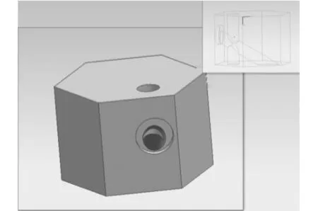
The simplified model of the part is shown in Fig.2, which is established in UG, and there is a hole with the diameter ofΦ=3 mm through upper and lower surfaces. At the same time, there is a step hole in the flank, and the hole is oblique and interlinked with the through hole. The tool is established in solidworks, as shown in Fig.3.

Fig.2 Simplified model of workpiece

Fig.3 A model of tool
2.2 Influence of cutting speed on parts
1) Influentce of different cutting speeds on cutting force
Take the cutting force of CFN1 whose force direction is consistent with the gun drill’s feed direction as an example to analyze the effect of cutting speed on cutting force. The cutting forces at the same feed rate off=0.016 mm/r and different spindle speeds ofn=500, 1 000, 2 200 and 3 200 r/min are shown as follows.
From Fig.4, it can be concluded that cutting force increases gradually with the increasing of spindle speed. Furthermore, with the increasing of cutting speed, cutting force tends to be gentle in the range of 500-2 200 r/min.

Fig.4 Influence of different spindle speeds on cutting force
2) Influentce of different cutting speeds on residual stress
It can be seen from Fig.5 that residual stress decreases gradually with the increase of spindle speed. When the rotational speed reaches 3 200 r/min, the residual stress tends to be moderate.
2.3 Influentce of feed rate of parts
1) Influentce of different feed rates on cutting force
The feed rate adopts four sets of parameters as follows:f=0.016, 0.025, 0.035 and 0.047 mm/r, and the simulation results are shown in Fig.6.

Fig.6 Effect of different feed rates on cutting force
The results show that the smaller feed rate is, the smaller cutting force is. The fluctuation tends to be more and gentler. Furthermore, most of them are concentrated in a certain value of vicinity.
2) Influentce of different feed rates on residual stress
Fig.7 shows the residual stress at different feed rates. It can be seen the residual stress decreases gradually with the decrease of feed rate. If feed rate is 0.016 mm/r, residual stress tends to be gentle.

Fig.7 Influence of different feed rate on residual stress
2.4 Optimization of cutting parameters
According to simulation results, cutting speed gets larger and feed rate gets smaller; surface quality becomes better, and the processing quality is relatively good when the cutting parameters adopt these values: spindle speedn=3 200 r/min, cutting speedv=30 m/min, feed ratef=0.016 mm/r.
Surface quality is better when optimization of cutting parameters is as follows: adopted in the simulation result during machining single hole. However, the left wall of the actual parts has a through step hole (see Fig.2). Surface roughness of the hole wall affects precision and quality at intersection of the two holes. Therefore the machining precision requirements of the surface of this hole wall is higher than that of the single one. The author makes sure that spindle speed and feed rate per tooth should be adjusted in a reasonable range(slower) according to the process analysis in combination with the actual production requirements.
The final optimization of cutting parameters is spindle speedn=3 100 r/min, cutting speedv=29.2 m/min and feed ratef=0.012 mm/r.
3 Conclusion
1) With the increasing of cutting speed, cutting force gets greater and tends to be gentler, and surface quality becomes better.
2) The cutting force decreases with the increasing of feed rate. The smaller feed rate is, the smaller fluctuation of cutting force is, which is mostly concentrated in the vicinity of 0. And the surface quality becomes better.
3) The residual stress decreases with the increasing of cutting speed, and reduces with the decreasing of the feed rate. That is, the bigger the cutting speed or the smaller the feed rate is, the better surface quality is.
4) Based on influence of multiple group cutting parameters on cutting force and residual stress of parts, optimized cutting parameters are spindle speedn=3 100 r/min, cutting speedv=29.2 m/min, feed ratef=0.012 mm/r.
[1] MA Hai-long, DUAN Hui, TANG Ai-jun. Survey on the deformation of milling thin-walled parts. Machine Tool & Hydraulics, 2010, 38(9): 117-119.
[2] TANG Dong-hong. Multi-objective optimization strategy for cutting parameters based on controlling face milling distortion. In: Proceedings of Advanced Manufacturing Technology and Systems, 2012.
[3] Vivancos J, Costa C J, Ortiz J A. Optimal machining parameters selection high speed milling of hardened steels for injection mould. Process Technology, 2004, (155): 1505-1512.
[4] RUI Zhi-yan, LI Chuan-ping, GUO Jing-feng, et al. Simulation study on cutting force during high speed machining titanium alloy based on abaqus/explicit. Machinery & Electronics, 2011, (4): 23-26.
[5] Hughes T J R, Liu W K, Zimmerman T K. Lagrangian-Eulerian finite element formulation for incompressible viscous flows. Computer Methods in Applied Mechanics and Engineering, 1981, (29): 329-349.
[6] Braess H, Wriggers P. Arbitrary Lagrangian-Eulerian finite element analysis of free surface flow. Computer Methods in Applied Mechanics and Engineering, 2000, (190): 95-109.
[7] Szabo P, Hassager O. Simulation of free surfaces in 3D with the arbitrary Lagrangian-Eulerian method. Internationa Journal for Numerical Methods in Engineering, 1995, 38: 717-734.
[8] Souli M, Zolesio J P. Arbitrary Lagrangian-Eulerian and free surface methods in fluid mechanics. Computer Methods in Applied Mechanics and Engineering, 2001, (191): 451-466.
[9] XI Ping, WANG Zhan-li, LI Jin, et al .The simulation analysis of milling force in the process of thin-walled milling. Manufacturing Automation, 2014, (36): 3-6.
[10] DING Ji-kai. Finite element simulation of the effect of cutting speed and cutting depth on cutting force. Science & Technology Information, 2012, (33): 41-42, 73.
[11] ZHAO Zeng-wu, XIN Jin, ZHANG Zhi-jing, et al. Simulation and modeling method for micro turn-milling cutting process. In: Proceedings of the 3nd International Conference on Digital Manufacturing &Automation(ICDMA2012), 2012.
[12] WANG Cong-kang. FEM simulation and deformation prediction of end milling machiningprocess of aeronautical frame monolithic components. Nanchang: Nanchang Hangkong University, 2011.
[13] LIU Ming-zhen. The estimation method tool-chip friction coefficient FEM for the influence of cutting parameters and for residual stress. Wuhan: Huazhong University of Science and Technology, 2012.
[14] Zorev N N. Inter-relationship between Shear Processes Occurring along Tool Face and on Shear plane in Metal Cutting. In: Proceedings of International Research in Production Engineering, New York, 1963: 42-49.
[15] SHEN Hao. Modern manufacturing technology foundation. Beijing: Electronic Industry Press, 2014.
[16] AI Xing, XIAO Shi-gang. Concise manual of cutting parameters. Beijing: Mechanical Industry Press, 1994.
[17] WANG Shi-qing. The Processing technology of deep hole. Xi’an: Northwestern Polytechnical University Press, 2003.
[18] PENG Lin-zhong, ZHANG Hong. Handbook of mechanical cutting process parameters. Beijing: Chemical Industry Press, 2010.
[19] The Chinese Society for Metals, Chinese Mechanical Engineering Society, Chinese Materials Research Society, Chinese Materials Engineering Canon Committee. China Materials Engineering Canon.Chemical Industry Press, 2006.
基于ABAQUS的小孔钻削加工仿真
研究了小孔径深孔钻削加工过程中切削参数对零件变形及残余应力的影响, 旨在获得不同切削参数下切削力和残余应力的变化规律。 对钻削加工工艺分析的基础上, 利用ABAQUS有限元仿真软件, 选择合适的材料模型和失效准则, 设定多组切削参数, 建立零件的三维钻削模型进行仿真。 结果表明, 根据仿真结果可优选合适的切削参数, 并预测切削力, 这为钻削的实际生产提供更直接的理论依据。
切削参数; 切削力; 残余应力; ABAQUS
WANG Yi-nuo, CHEN Cong-jian. Simulation of small-aperture deep hole drilling based on ABAQUS. Journal of Measurement Science and Instrumentation, 2015, 6(3): 296-301. [
王依诺, 陈从建
(中北大学 机电工程学院, 山西 太原 030051)
10.3969/j.issn.1674-8042.2015.03.017]
Received date: 2015-05-23 Foundation items: Shanxi Province Scientific and Technological Research Program (No.20140321008-03)
WANG Yi-nuo (wangyinuo1016@163.com)
1674-8042(2015)03-0296-06 doi: 10.3969/j.issn.1674-8042.2015.03.017
CLD number: TG52 Document code: A
猜你喜欢
杂志排行
Journal of Measurement Science and Instrumentation的其它文章
- Modal analysis of 4-cylinder engine crankshaft based on ANSYS Workbench
- Investigation on nonlinear rolling dynamics of amphibious vehicle under wind and wave load
- Numerical simulation of two-phase flow field in underwater sealing device based on dynamic mesh
- Analysis of movement laws of fragment and shock wave from a blast fragmentation warhead
- Application of adaptive Kalman filter in rocket impact point estimation
- X-ray image distortion correction based on SVR
