Study on modeling and simulation of multi-inertia servo system of CNC machine tool based on Simulink
2015-02-24FengyongSHAJunGAOXueweiLIChaoLUOFeiLUO
Feng-yong SHA,Jun GAO,Xue-wei LI,Chao LUO,Fei LUO
(School of Mechanical Engineering,Shandong University of Technology,Zibo 255049,China)
1 Introduction
The servo feed system of Computer Numerical Control(CNC)affects the performance of the machine directly.The Servo feed system is a closed loop control system.Its dynamic characteristics depend on the structure of system and parameters of the components,such as inertia,stiffness,damping,friction,gain,etc.Difference of servo parameters will cause a certain effect to the servo system.In order to study the impact of the servo system on CNC machine tools more accurately,the mathematical model should be established correspondingly[1].
At present,in the dynamics modeling,there are three most common models in the CNC machine:lumped parameter model,distribut-ed mass model and finite element model[2].Regarding to the first two methods,the mo-deling accuracy of them is not high,the computation work is much,and the work state and the dynamic response of the system can be ignored.The finite element method is rela-tively complicated,it needs the 3D model,ANSYS or Matlab software to analyze jointly,the amount of calculation is large[3].
For dynamics modeling of servo feed system,a method is proposed.Transform the servo feed system to a multi-inertia system,and divide it into three units(motor,screw,bench),connectors(coupling nut and screw nut)between the units are equivalent to the flexible joint.Based on the three closed-loop control system of PID,using simulation module of Matlab/Simulink to Permanent Magnet Synchronous Motor(PMSM),all aspects of the mechanical parts,setting and optimizing paraters.Through the simulation of MATLAB,the calculation process is simplified.The accuracy of the simulation model and parameter setting algorithm is improved,and the simulation results are good.
2 Feeding system model
The CNC feed system is divided into two parts:one is the servo drive system,the other is the mechanical transmission system[4].The strcture diagram of the CNC machine tool feed system is shown in Fig.1.
2.1 Modeling of servo drive system
The motor of the servo drive system adopts PMSM.In the Matlab/Simulink environment,establishing and combining the vector control simulation model,PID controller simulation model,Sinusoidal Pulse-Width Modulation(SPWM)simulation model,PMSM and inverter simulation model and other functional modules[5].Speed and current double closed loop simulation model of permanent magnet synchronous motor control system is constructed.The simulation model of PMSM vector control system is shown in Fig.2.
2.2 Mechanical transmission system
The mechanical transmission mechanism is composed of the drive motor,coupling,ball screw pair,screw bearing,screw nut,bench,etc[6].The input of mechanical transmission system is the angular displacement of the servo motor(θ(t)),the output is the movement of the execution unit(X(t)).The schematic diagram agram of the mechanical transmission mechanism,as shown in Fig.3.

Fig.1 The structure diagram of the CNCmachine tool feed system
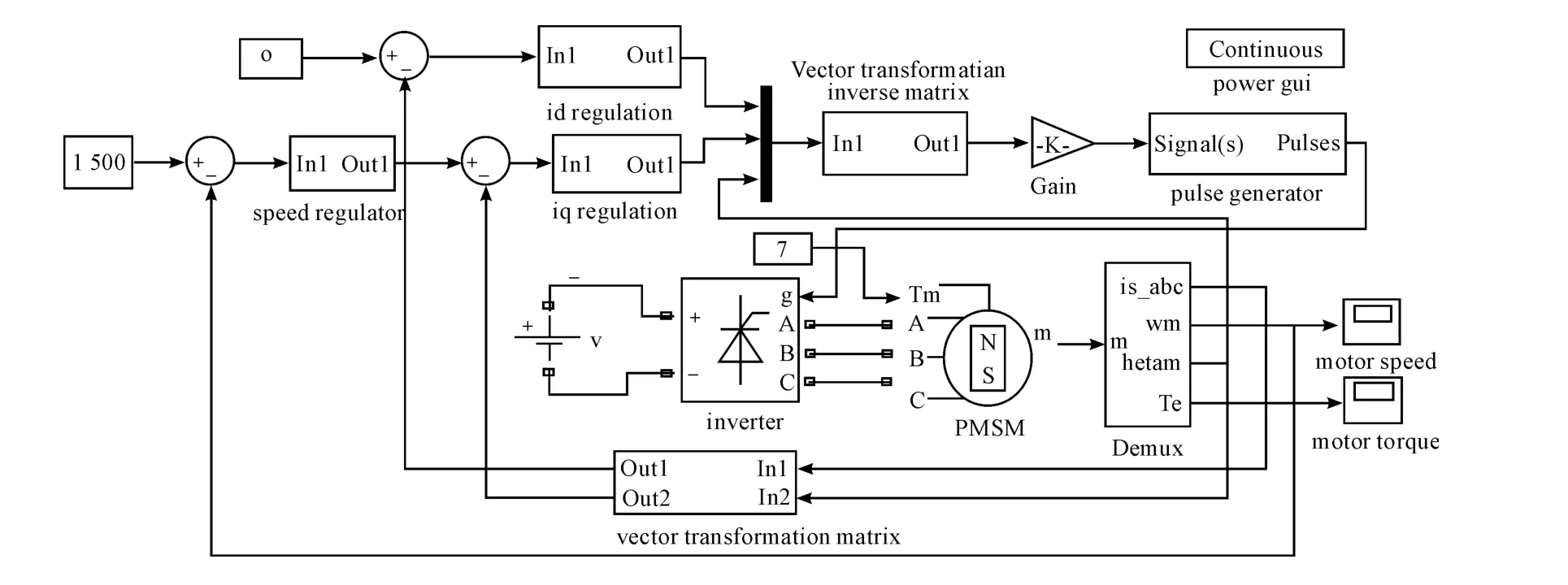
Fig.2 The simulation model of PMSM vector control system

Fig.3 The schematic diagram of the mechanical transmission mechanism
In Fig.3,there are rigid elements and viscous elements.Damping and torque are pr-esent in each moment of inertia.The system can be divided into three units:motor,screw,bench[7].As shown in Fig.4,the stiffness,inertia,damping and disturbance torque of the mechanical transmission device are distributed among the units and units.
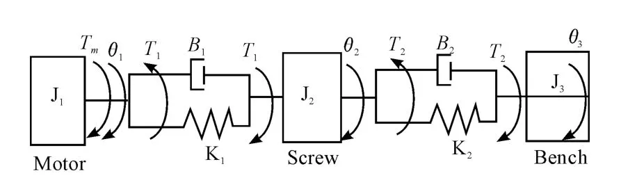
Fig.4 The dynamic model of the mechanical transmission device
In Fig.4,the coupling is equivalent to an elastic coefficientK1,damping coefficientB1.The screw nut is equivalent to the elastic coe-fficientK2,damping coefficientB2.Moment of inertia of the motor and coupling equivalent to the moment of inertia of the motor shaft-J1.The moment of inertia of the screw isJ2,and the moment of inertia of the bench isJ3.Driving torque of the motor isTm,driving torque of the screw isT1,and driving torque of the bench isT2.The output angle of the motor and shaft is equivalent to the output angle of the motor shaft-θ1.The output angle of the screw is θ2,the output angle of the bench is θ3[8].
3 Modeling method of multi-inertia system
3.1 Parameter tuning of PMSM
The vector control system of PMSM has the excitation current regulator,torque current regulator and speed regulator.By the PI regulator,the excitation current regulator and the torque current regulator are adjusted to the standard I system,which can improve the dynamic response of the system,and the speed loop is adjusted to the standard II type system,which can improve the anti jamming capability[9].
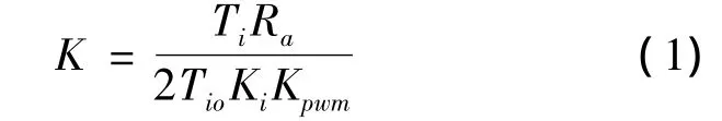
By the principle of“optimal parameters of I system engineering”,the parameters of the current loop regulator are derived:
According to the principle of“minimum resonant peakMP”in the II type system,the parameter formula of speed loop regulator is derived:
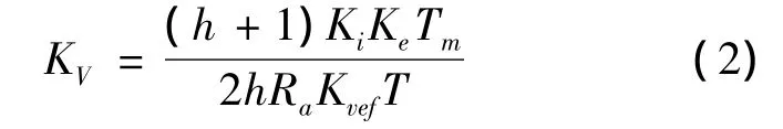
In the formula(2),his the Intermediate Frequency bandwidth.According to the prin-ciple of the“third-order engineering best”,h=5.By formula(1)and(2),the parameters of the excitation current regulator,the torque cur-rent regulator and the speed regulator are calculated,as shown in Table 1.
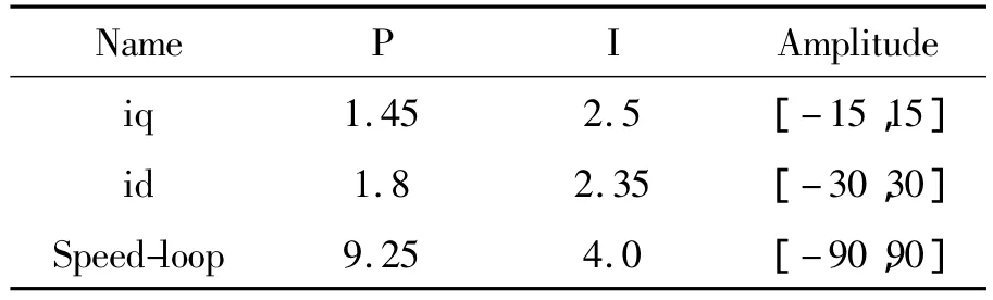
Table1 PI regulator parameter
3.2 Modeling method of mechanical system
In Fig.4,the establishment of differen-tial equations:
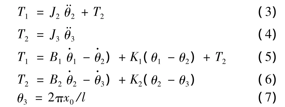
Establishing transfer function:
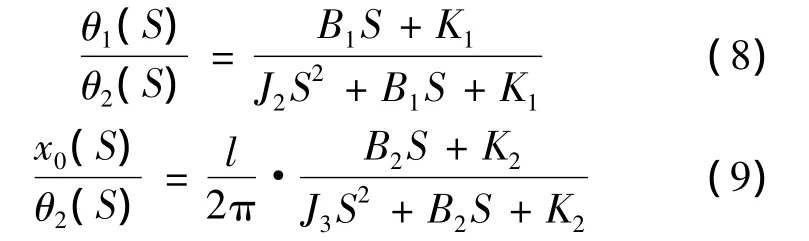
The elastic coefficient and damping coeff icient of the transfer function determine the stability of the mechanical system.
According to empirical formula,the formula of elasticity coefficient is obtained:

In the formula(10),dis the elastic element diameter,Gis the elastic modulus,Lis the elastic variable length.
According to the Lehr principle,the damping coefficient formula:
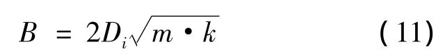
Wheremis the damping element mass,Difor the relevant material damping coefficient,kfor the elastic coefficient.
According to the formula(10),(11),the elastic coefficient and damping coefficient of the connecting piece are shown in Table 2.
4 Simulation
4.1 Basic parameters
The basic parameters of the motor,PMSM parame-ters,as shown in Table 3.The Simulation parameters of the system,as shown in Table 4.
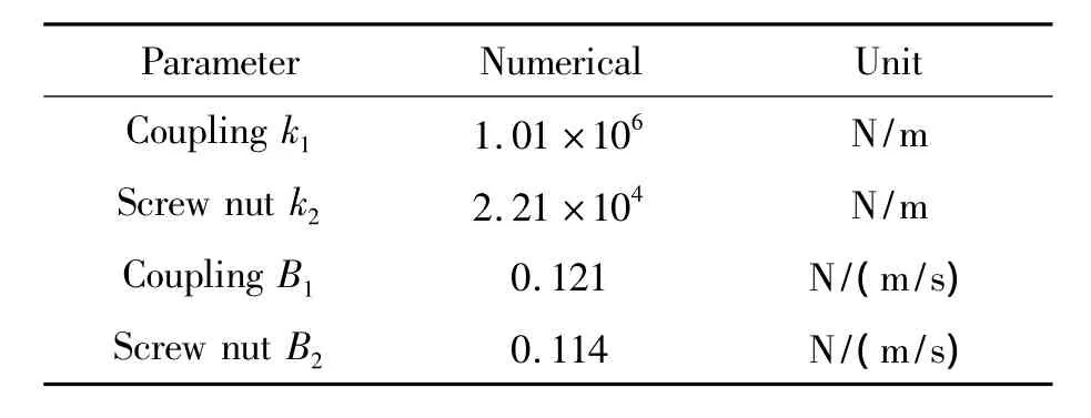
Table2 The elastic coefficient and damping coefficient

Table3 PMSM parameters

Table4 Simulation parameters of the system
4.2 The motor of simulation
The motor’s rotation speed is 1 500 r/min,while the torque is 7 N·m [10].As shown in Fig.5,the motor output speed and torque curve are obtained by using the traditional PI algorithm.As shown in Fig.6,the motor output speed and torque curve are obtained by using the new PI algorithm.
MATLAB simulation results show that the new PI algorithm can shorten the response time of the motor output speed and torque from 0.04 s to 0.01 s,and the response speed of the system is improved,and the response is stable.
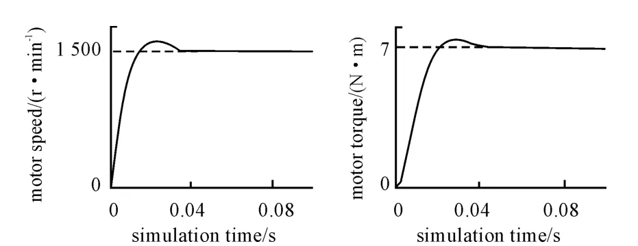
Fig.5 The motor output speed and torque curve are obtained by using the traditional PI algorithm
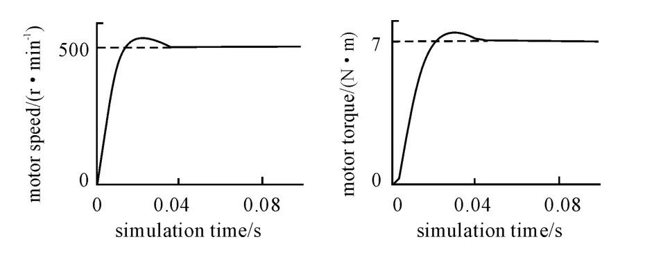
Fig.6 The motor output speed and torque curve are obtained by using the new PI algorithm
4.3 Simulation of the servo feed system
The permanent magnet synchronous motor vector simulation model is encapsulated into a subsystem module(PMSM).In the Simulink interface,with the model of PMSM and mechanical transmission system,the simu-lation model of the multi inertia servo feed system is established.The simulation model of the feed system is shown in Fig.7.
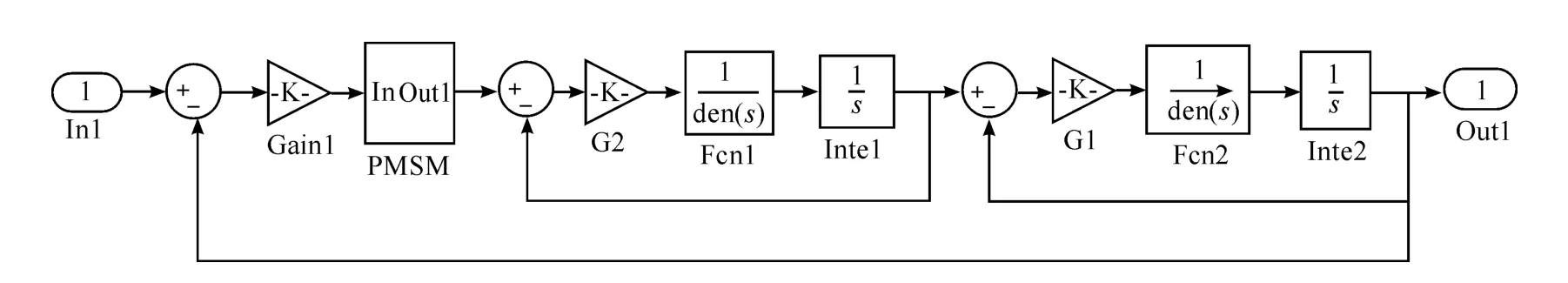
Fig.7 The Simulation model of the feed system
The position loop regulator of the system is adjusted by proportional gain factorKP.The numerical value ofKPis determined by MATLAB/simulink software.The proportional gain of the position loop is set at the minimum value of the empirical value.After adjusting the speed loop,the amount ofKPis gradually increased until the system has no overshoot,and the final value ofKPis 12.
Under the same conditions,the compa-rison between the double-inertia system and multi-inertia system is shown in Fig.8.
The simulation results of MATLAB show that the simulation response time of the multi-inertia servo feed system is 0.2 s,which was reduced by 50%compared with the simulation response time of the double-inertia system.
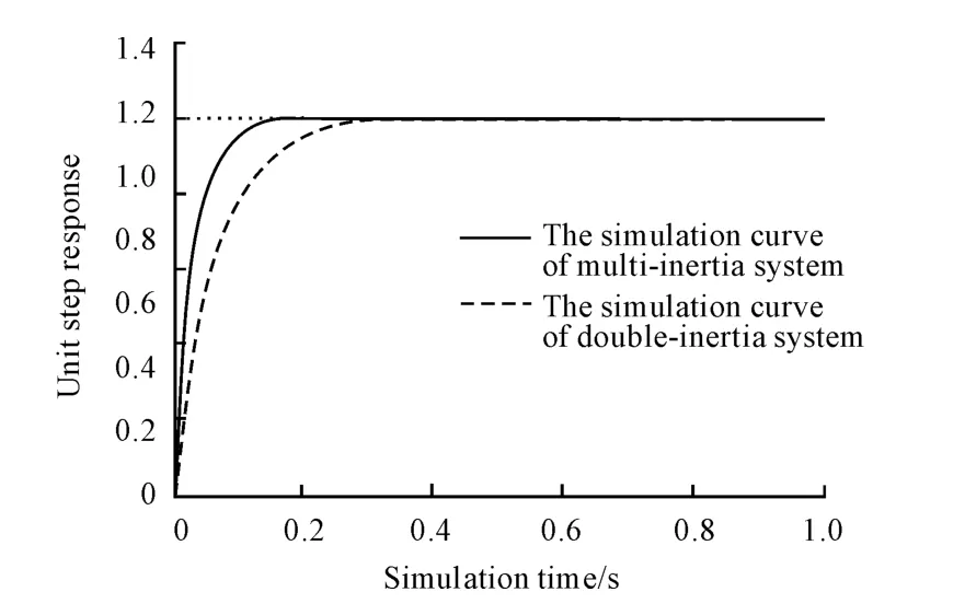
Fig.8 Thestep responsesimulation diagram of double/multi inertia servo system
5 Conclusions
Through the modular modeling method,the multi inertia servo feed system is analyzed,and the new algorithm is derived,and the parameters are determined.Compared with the traditional method,the new method reduces the response time of the motor,as well as the mechanical system,and the system speed,torque and the system step signal are stable.It makes the simulation process more close to the actual operation of the machine tool.
[1]Su Hongzhi.Modeling and simulation of PID control of NC machine tool servo system[J].International Mechatronics Technology,2010,23(1):37-39.
[2]Song Yu,Chen Guoding,Ma shuwen.Research on mathematical model and simulation of AC servo system[J].Mechanical Design and Research,2010,37(7):9-12.
[3]Wang Can,Yang Ming,Xu Dianguo.Suppression of mechanical resonance of a double inertia system based on PI control[J].Electric Drive,2015,45(1):49-53.
[4]Cao Wenzhi,Sun Mingjia,Ma Xiaobo.Research on simulation technology of machine tool servo system based on Simulink[J].Manufacturing Automation,2013,35(4):115-118.
[5]Hu Hao,Yang Ming,Xu Dianguo.The cause and suppression of mechanical resonance of permanent magnet AC servo system [J].Journal of Motor and Control,2012,16(2):79-84.
[6]Muszynski R,Deskur J.Damping of torsional vibrations in high-dynamic industrial dri-ve[J].IEEE.Trans.Ind.Electron.,2010,57(2):544-552.
[7]Wang Hui,Wang Xiaohong.Analysis and modeling of the AC servo feed system of K6136[J].Modern Commercial Industry,2009,(2):307-308.
[8]Ma Xiaoliang.Speed drive for flexible load[J].Electrical Drive,2008,38(7):3-7.
[9]Harnefors L.Implementation of resonant controllers and filters in fixed-point arith-metic[J].IEEE.Trans.Ind.Electron,Apr.2009,56(4):1273-1281.
[10]Kang C I,Kim C H.An adaptive notch filter for suppressing mechanical resonance in high track density disk drives[J].Microsystem Technologies,2005,11(8-10):638-652.
杂志排行

机床与液压的其它文章
- Co-simulation and consumption analysis of wheel loader on negative loading condition
- Study on rigid-flexible coupling multi-body dynamic model and simulation for wind turbine
- Introduction of the Fluid Control Engineering Institute of Kunming University of Science and Technology
- Influence of the underlap in the poppet valve on its performance
- The research on engine stable frame report parsing of Boeing 747-400 by QAR data
- Comprehensive reliability evaluation of foreign high-end gantry machining Center