Influence of the underlap in the poppet valve on its performance
2015-02-24郭晓霞,马彦伟,张勇等
1 Introduction
The valvistor valve has some advantages,such as large flow,simple structure,easy processing,good static and dynamic performance,etc.Valvistor valve is widely applied in various engineering machinery and hydraulic systems,and the domestic and foreign scholars have studied on its performances in details.The dynamic mathematical models of Valvistor main valve and pilot valve are established and simplified to the first-order model and its static and dynamic characteristics are studied in details by Eriksson[1-2].Literature[3]applied valvistor valve flow amplifying principle to three four-way proportionaldirection valve.Literature[4]established 3D model of the new type of proportional direction valve,and carried out the simulation.The results showed that the valve had good static and dynamic performances.Literature[5]proposed anew concept of two-way valvistor,experimental research showed that the flow capability,static and dynamic characteristics of the new valve were improved obviously.Literature[6] studied the main valve core displacement electric closed loop feedback proportional throttle valve by simulation,the results showed that the electric closed-loop proportional cartridge valve had excellent control characteristic and dynamic characteristic.
Domestic and foreign scholars have conducted a detailed study on valvistor valve performances.But the study about the cause of increasing underlap in the poppet valve and the effects of underlap on the performance of poppet valvewere less,therefore studying the effect of underlap on performance of the valve core,and then selecting the appropriate underlap is of great significance to improve the performance of poppet valve.This paper establisheda simulation model by using SimulationXto study valvistor valve performances,and the simulation results were verified by experiments,and the effect of the underlap on the performance of the valve corewas studiedas well.
2 The working principle and mathematical model
The working principle of valvistoris given in Fig.1.When pilot valve port is closed,the control chamber is filled with oil which flows through slot in the main valve from inlet of main poppet.Due to same pressure of upper and lower chambers,spring force and the upper and lower area differential,main poppet is in the state of shut.Then the pressure of the control chamber gets decreased when the oil flows through pilot poppet to the outlet of main poppet,and main poppet moves up when pilot valve port opens.It comes to steady state when main poppet stops moving with the flow of feedback notch and pilot poppet being the same.
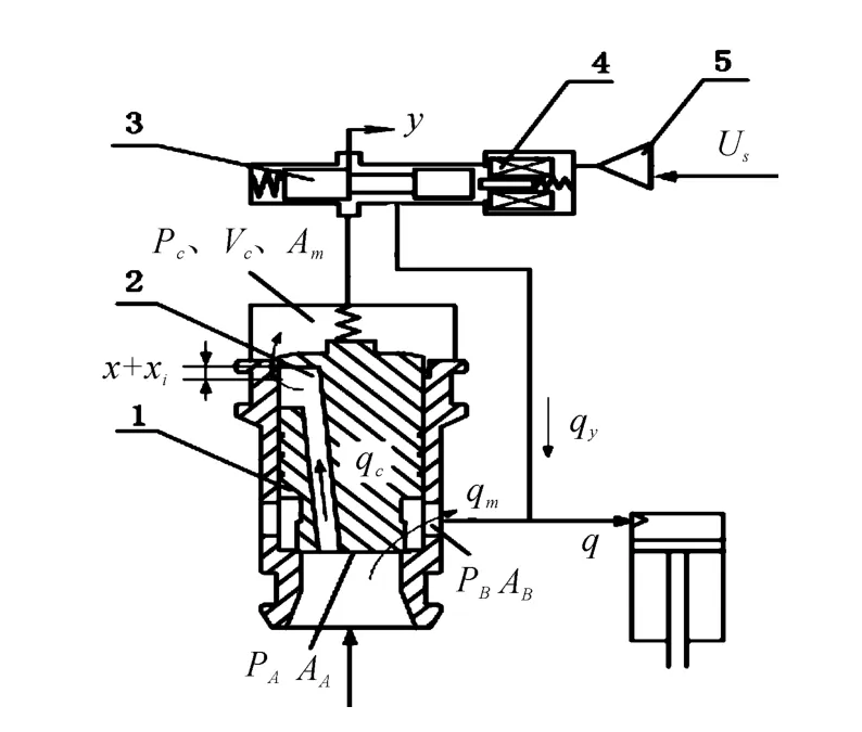
Fig.1 Working principle of the Valvistor valve
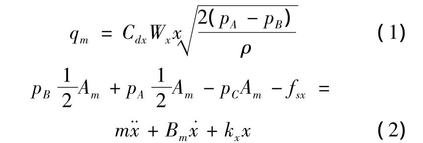
During the process of valve core movement,assume the inlet pressurePA,outlet pressurePBare constant.The flow through the main orifice and dynamic equilibrium equation of the valve spool could be obtained as follows:
The flow through the pilot valve port could be evaluated as follows:

The flow through the feedback notch and pressure of control chamber could be calculated as follows:

When the valve spool is stable,neglecting spring force and flow force,the equation(2)can be modified as:
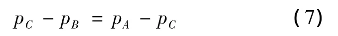
At this time the flow through the feedback notch and pilot valve are the same.
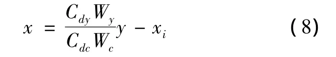
The static mathematical model of the main valve is as follows:

Compared with the main valve,pilot valve dynamic characteristic could be ignored.The transfer function betweenYandQcould be written as follows:

Ignoring the damping coefficientBmand steady fluid force,the system stability condition is:

PA0,PB0,y0are the pressure and displacement of pilot valve,respectively,when the valve core is steady.From stability conditions(11),the valve core stability is connected with pilot valve openingy0,control cavity volumeVC,narrow groove widthWCand other factors.
3 Simulation and experimental study
The simulation model of size 16 valvistor established by using SimulationXis shown in Fig.2.The model consists of electronic controllers,pilot valve,main valve,pressure source,load,fuel tank and other parts.This system adopts constant voltage source to supply oil.The main valve core can be equivalent to a spring mass damper system,three piston components in the component library to represent the main valve control chamber,inlet chamber and outlet chamber,the model of main valve and feedback narrow groove are modeled by using valve edge,annular gap represents the leakage of the main valve.Because the structure and size of the pilot valve core is unknown,2-way proportional valve is used to model and the flow characteristic curve of the pilot valve import the simulation model to ensure that the model is correct.Return fuel back-pressure is equivalent to that of a throttle valve.

Fig.2 Simulation model
The experimental platform of size 16 valvistor is shown in Fig.3.Pilot valve is Rexroth tri-positionfourwayelectro-hydraulic proportional valve(4WRPEH6)with close loop electro control.Three pressure sensors are used to measure the inlet pressurePi,outlet pressurePoand control pressurePc.In addition,two flow sensors(SCVF-015-10-01 andSCVF-150-10-07)are used to measure main valve volume flow rateQmand pilot valve volume flow rateQy.The Rexroth variable displacement plunger pump(SYDFEE-11/71RN00)is used for oil supply.The dSPACE is used to supply voltage signal for pilot valve and receive the signal from all these sensors.
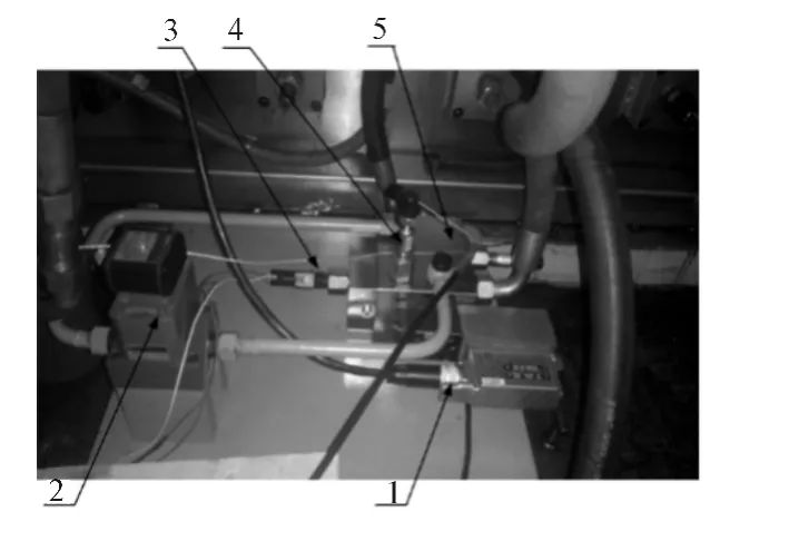
Fig.3 The experimental platform
Fig.4,and 5 show valve core static and dynamic characteristics,respectively,when the pressure difference is 2 MPa.From Fig.4,it could be known that valve core exists about 10%of dead zone.When pilot valve voltage is smaller,main valve flow linear degrees is better.However,with pilot valve voltage increasing,linear degrees variable becomes poor,we can know that main valve flow rate related to the displacementyof pilot valve and pressure difference from equation(9).Because there is back-pressure in experiment and the inlet pressure gets decreased slightly when flow rate increases,but inlet pressure is constant in simulation,so the outlet pressure cannot be guaranteed identical to the experimental back-pressure,which leads to a slightly difference between the simulation results and experimental data.The static and dynamic characteristics of the valve core are approximate in simulation and experiment results,and it verifies the correctness of simulation model.
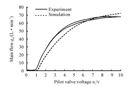
Fig.4 Characteristic curve of valve flow for Δp=2 MPa
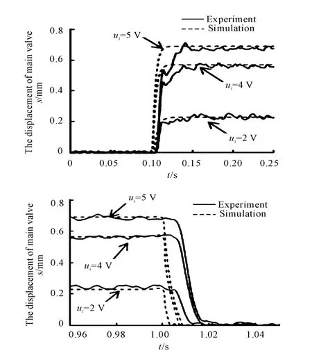
Fig.5 Step response for Δp=2 MPa
4 The influence of underlap on performance of valve spool

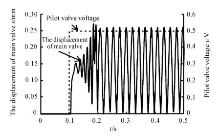
Fig.6 Response of main valve whenxi=0.1 mm

Fig.7 Response of main valve whenxi=0.4 mm
As shown in Fig.8,the main valve underlap is set at 0 mm,the pilot valve voltage is zero between 0 to 0.1 s,and a 2 V voltage is applied to pilot valve at 0.1 s;from the Fig.8,it can be seen that the main valve always own a 0.07 mm displacement when the pilot valve voltage is zero.So there must exist a underlap for feedback narrow groove to make the oil inlet chamber connect to the main valve superior chamber,meanwhile the pressure of main valve superior chamber is equal to the inlet pressure and the area of superior chamber is twice greater than that of inferior chamber,and the valve closes under the area difference.
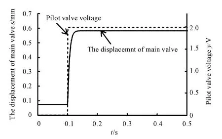
Fig.8 Response of main valve whenxi=0 mm
The increase of underlap will ensure the stability at the small opening condition,but it will lead to the dead zone and poor linearity.And the underlap is larger,the dead zone will be larger.Fig.8,9 shows valve spool displacement and flow characteristics when the underlaps are 0.2 mm and 0.4 mm and the pressure differential between inlet and outlet is 3 MPa.It can be seen from the simulation results that the valve spool dead zone reduces from 10%to 5%when the underlap gets reduced from 0.4 mm to 0.2 mm.
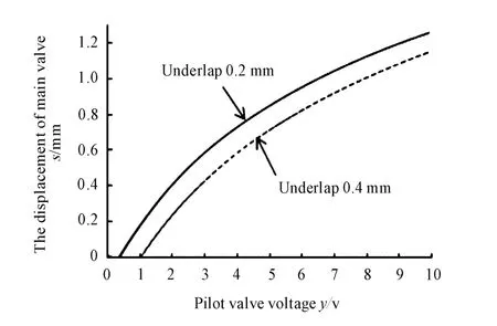
Fig.9 Characteristic curve of valve displacement in different underlap for Δp=3 MPa
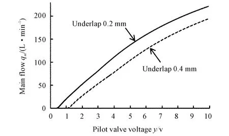
Fig.10 Characteristic curve of main valve flow in different underlap for Δp=3 MPa
As shown in Fig.9.Dashed line and solid line are the flow characteristics when the underlap are 0.2 mm and 0.4 mm,respectively,and the simulation results show that the increase of underlap will lead to the decrease of linearity and current capacity.It is consistent with those of theoretical analysis.
5 Conclusions
Underlap of valve valvistor was studied by using the simulation model,and the simulation results are consistent with those of theoretical analysis,based on the experimental and simulation results,the following conclusions could be drawn.
1)In order to increase the stability of valve core and make the main valve close completely when the pilot valve is zero,the underlap of valvistor valve must be increased.
2)If the underlap is larger,the dead zone will be larger and main valve linearity and flow ability will get worse.
3)If the underlap is larger,main valve core displacement will be smaller,namely the amount of the main valve stroke will be decreased.
[1]Eriksson B,Andersson B R,Palmberg J O.The dynamic properties of a poppet type hydraulic flow amplifier[C]//Proceedings of the 10th Scandinavian International Conference on Fluid Power,SICFP’07,May 21-23,2007,Tampere University of Technology,Tampere,Finland,2007:161-178.
[2]Eriksson B,Andersson B,Palmberg J O.The Dynamic Performance of a Pilot Stage in the Poppet Type Hydraulic Flow Amplifier[C]//The 51st NCFP Technical Conference,2008.Proceedings of the 51st NCFP Technical Conference:Omnipress,2008:659-668.
[3]Quan L,Xu XQ,Yan Z,et al.A New Kind of Pilot Controlled Proportional Direction Valve with Internal Flow Feedback[J].Chinese Journal of Mechanical Engineering,2010,01:60-65.
[4]Wang S F,Zhao H,Quan L.Simulation of the Dynamic Characteristics for a New Type Proportional Direction Valve[J].Hydraulics Pneumatics & Seals,2013(6):35-39.
[5]Eriksson B,Larsson J,Palmberg J O.A novel valve concept including the valvistor poppet valve[C]//The Tenth Scandinavian International Conference on Fluid Power.Tampere,Finland:Tampere University of Technology,2007:438-444.
[6]Pang J F,Quan L,Jin ZF.Characteristics Research of Cartridge Electrical Closed-loop Proportional Throttle Valve[J].Fluid Power Transmission &Control,2011,3:10-13.
杂志排行

机床与液压的其它文章
- Co-simulation and consumption analysis of wheel loader on negative loading condition
- Study on rigid-flexible coupling multi-body dynamic model and simulation for wind turbine
- Introduction of the Fluid Control Engineering Institute of Kunming University of Science and Technology
- The research on engine stable frame report parsing of Boeing 747-400 by QAR data
- Comprehensive reliability evaluation of foreign high-end gantry machining Center
- Analysis of contact stress on interference fitted surface of the train axle-bearing