Over-constraint and a Unified Mobility Method for General Spatial Mechanisms Part 1:Essential Principle
2015-01-20ZENGDaxingLUWenjuanandHUANGZhen
ZENG Daxing,LU Wenjuan,and HUANG Zhen*
School of Mechanical Engineering,Yanshan University,Qinhuangdao 066004,China
1 Introduction
As the basic problem in the field of mechanism,the mobility calculation is the most basic point to confirm the right type-choice among various proposed novel mechanisms,at the initial stage of mechanical design.Even for the simplest mechanism,it is inevitable to identify its mobility.So far the mobility formulas of plane and spatial mechanisms have been widely used and introduced in every mechanical text book[1-4],and they are as follows:
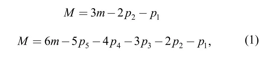
whereMdenotes the mobility of mechanism,mdenotes the number of all active components,ipthe number of kinematic pairs withiconstraints.Commonly,the above formulas are called Grübler-Kutzbach(G-K) formula,which has a more common expression form as follows:
wheredis the order of the mechanism,andd=6-λ,λdenotes the common constraints of the mechanism;nthe number of all components (including the frame);gthe number of kinematic pairs andfirepresents the mobility ofithkinematic pair.
The above-mentioned G-K formula is merely based on the number of links,the type and number of kinematic pairs,via simple arithmetical operation.By using the G-K formula,mobility issues of various mechanisms have been correctly solved,especially for the numerous planar ones.
However,during the recent 150 years,the traditional G-K formula faces many counterexamples and problems.In the latter half century,the emergence and application of parallel mechanisms have gained a lot of merits and attracted many researchers,and meanwhile many new troubles have been ceaselessly found.That is because most of these mechanisms are over-constrained,and the G-K criterion completely fails to analyze them.The traditional method brings a lot of mistakes,which seriously affects the mechanism innovation.
For all modern mechanisms,the mobility analysis should be able to satisfy the following three conditions:
(1) The mobility formula should be general and universal and can suit all mechanisms;
(2) The mobility analysis should be able to estimate and identify the mobility properties:revolute,translate or screw motion;
(3) The mobility principle and formula should also be as simple as possible to be understood and held by numerous engineers.
In 2005,GOGU[5]systematically enumerated a great number of so-called“puzzle”and“paradoxical”mechanisms,and also pointed out that no one“unified formula”can be successful to solve these mechanisms,which were categorized by him into classical mechanisms and modern parallel mechanisms,including:ALTMANN[6],BAKER[7-8],BENNETT[9],BRICARD[10],DELASSUS[11-12],ECKHARDT[13],GOLDBERG[14],HERVE[15-16],MYARD[17],MABIE,et al[18],NORTON[19],PHILLIPS[20],WALDRON[21],CARRICATO,et al[22],WENGER,et al[23],and GOGU[24].This can be called“GOGU open problem”and is one of the most difficult issues in machinery and has become a heated research point in the academic community in the beginning of the 21st century.This would be a great significance to establish a valid and unified mobility criterion.
The reason for such difficulty lies in the appearance of over-constraints or virtual constraints in mechanisms,which are calculated repeatedly in the G-K formula although they have no impact on the motion.So the over-constraints have to be identified and removed in the mobility analysis.
After the first mobility formula was proposed by CHEBYCHEV in 1854[25],many important progresses concerning mobility analysis have been made by researchers,such as HUNT,et al[26-27],WALDRON[28],BAGCI[29],DAVIES[30],ZHANG[31],AGRAWAL,et al[32],ANGELES,et al[33],ALIZADE[34],TSAI[35],MCCARTHY[36],WALDRON[37],RICO,et al[38],LIN,et al[39],XU,et al[40-41].
Those scholars have all made many important progresses and found many methods in various aspects.However,some counterexamples arise from those methods and some other methods are claimed to be only suitable for parallel mechanisms.Some are claimed to be universal but they cannot recognize mobility nature encompassing revolution or translation.Therefore,these researches cannot simultaneously satisfy above three important mobility analysis conditions.
The researches of WALDRON[28]and BAKER[42]successfully analyzed the mobility of some multi-loop mechanisms by incursion of the screw theory,and this is an important development for mobility analysis.However,the intersection operation of some motion screw systems is adopted in their calculations,and this is a difficult algebraic issue and their results are obtained only through simple linkages.Based on the screw theory they proposed,HUANG continued to use the screw theory but turned to adopt the reciprocal screw,and meanwhile the simple union operation of the constraint screw systems is taken instead of the complicated intersection operation of the motion screw system,and then the whole above-mentioned problem is solved rapidly.
In 1997,HUANG firstly found a solution of the overconstraints problems in parallel mechanisms based on the reciprocal screw theory.The corresponding principles and methods for mobility analysis were proposed in his book[43],and the classical DELASSUS,SARRUS mechanisms as well as the modern 3-RRRH parallel mechanism with over-constraint were firstly analyzed successfully by using an identical formula.Further,the above-mentioned three mobility analysis conditions are satisfied completely.In the subsequent decades,HUANG more systematically presented the basic theory and the new mobility formula,named as“modified G-K formula”.Recently,he enriched and expanded his theories,and systematically analyzed all the“puzzle”and“paradoxical”mechanisms proposed by GOGU[5],including the modern mechanisms and the classical mechanisms,and that systematic research has been published in his new books[44-45].
However,for a really universal mobility formula and method,it is supposed be suitable for all mechanisms,including what has been discovered and applied.The above-mentioned researches were only limited in the modern parallel mechanisms as well as the classical mechanisms.However,two other important categories are not discussed and people still do not know how to correctly solve them.One is the planar mechanism and the other is the GMSMs,both of which are also widely used in practice.Although for the former many planar linkages with over-constraint have been recognized by various methods,the problem is that there still is no unified criterion and way to recognize the over-constraint,and in other words,there is no unified and trustworthy method;and for the latter the GMSMs,however,are more serious than the parallel mechanisms,and has been ignored.
The severity of the GMSMs is derived from its multi-loop structure,and since that the identification of over-constraints has to adopt the reclosing processes of all its loops one by one.However,for the parallel mechanisms with multi-loop all its over-constraints can be completely identified by only one reclosing i.e.one step.In addition,there still exists motive coupling and even strong coupling within the different loops in the GMSMs.The asynchronism of multi-loop closing and the strong coupling make the over-constraints quite difficult and complex to recognize and till now it has been in darkness,which is another big challenge in the academic area.
This paper aims to extend the application of the reciprocal screw theory to the GMSMs.Thus,it is of important realistic meaning and also will further develop the present mobility theory.
2 Over-Constraints in the Mechanism
2.1 Occurrence of over-constraints
The over-constraint may appear when the end-link of a serial chain is connected with the frame to form a closed loop,namely,over-constraints usually occur when kinematic chains are closed.
Though closing ways of kinematic chains are various,the basic way is the transformation of a serial chain into a single closed-loop mechanism with identical number of kinematic pairs,and then over-constraint occurs in the process[28,31].
To simplify the mobility analysis,firstly three theorems are presented as follows:
Theorem 1:Over-constraints in mechanisms only occur when the kinematic chain is closed,and there is not any over-constraint in serial chains.
Theorem 2:Over-constraints appear when linear dependence of the constraint screw system of the studied link happens.
Theorem 3:For a single-loop mechanism,the number of over-constraints is equal to the number of independent reciprocal screws of the mechanism.
As theorem 1,over-constraint only appears during the closing process of the serial chain.According to the different closing ways,the over-constraints can be confirmed by checking the relative motion between the two closed elements.
2.2 Closure ways of mechanisms
2.2.1 Rigid closure
A single-loop linkage is formed by connecting the end-link of a serial chain rigidly to the frame.For this situation the number of kinematic pairs does not change.This closing way is called rigid closure.Any rigid closure can impose six constraints on the mechanism.If the mobility of the end of a serial chain isδ,it is imposed by 6-δconstraints before the rigid closure,which are constrained once more in closure,namely,over-constraints caused by the rigid closure are
A single-loop mechanism is shown in Fig.1(a).If the over-constraint needs to be identified by rigid closure,the linkAGshould be cut at the sectionm-mand a serial open kinematic chain can be obtained,as shown in Fig.1(b).When the opened kinematic chain is reclosed again,it is a rigid closure.For the purpose of analyzing the number and properties of the over-constraints after the closure,the steps are presented as follows:
Step 1:Establish the motion screw system of the serial kinematic chain,and calculate their reciprocal screws.The mobility number and property of the end-link are obtained.
Step 2:Connect the end of the serial chain with the frame again,the over-constraints will be produced,the number of the over-constraints is just the number of reciprocal screws of its motion screw system.
This is a very common method to analyze overconstraints in mechanisms.
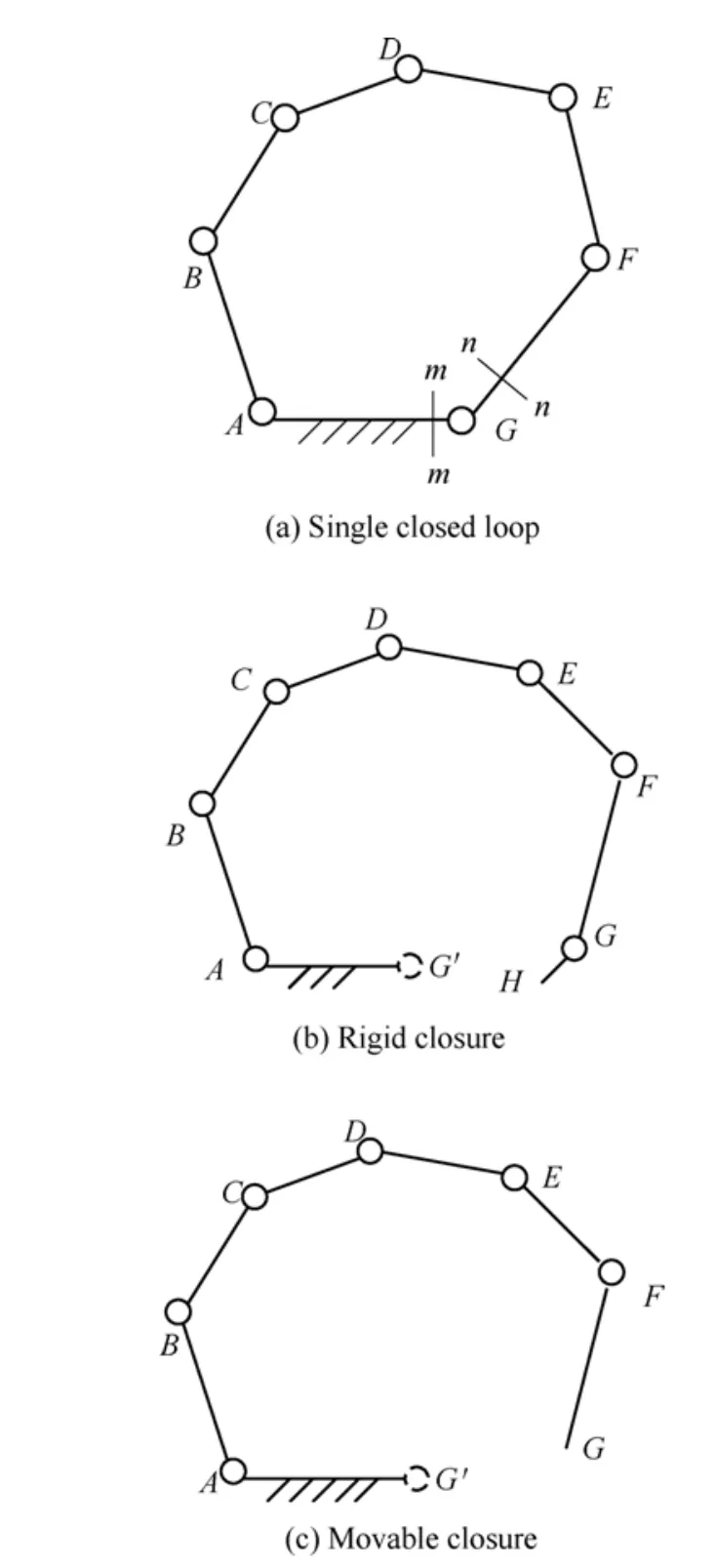
Fig.1.Closing forms of single closed loop mechanism
2.2.2 Movable closure
Process of combining the serial chain containingδdegree of freedoms(DOFs) with the frame to obtain a single-loop mechanism via an extra one-DOF kinematic pair is named movable closure,and the pair is named as closure pair.Apparently,compared with the series chain,the single-loop mechanism contains a new kinematic pair.Supposedenotes serial chain's kinematic screw systems which haveδDOFs,anddenotes the single-loop mechanism's screw system,two situations are as follows.
As for the single-loop mechanism obtained and reclosed by adding a multi-DOF kinematic pair or multi-DOF serial chain,there are similar methods to deal with.
If the single-loop mechanism,as shown in Fig.1,is checked with the movable closure,rodFGcan be truncated from the sectionn-nand a serial kinematic chain can be obtained,as shown in Fig.1(c).In order to maintain the original mechanism invariant after movable closure,when it is reclosed again,a closure pairGis entailed.For the purpose of analyzing the number and property of over-constraints in the process of movable closure,steps are defined as follows:
Step 1:Establish the motion screw system of the serial kinematic chain,
Step 2:Establish the motion screw of closure pairs.
2.2.3 Dynamic closure
It means let respectively the two ends of an open-chain connect with the two active components of another closure loop,shown in Fig.2(a).This is a more general and more sophisticated closing method.As for this kind of closing,the relative movements of the connected components are imperative,and by checking the relative motions between the two closed elements,over-constraints can be determined.By means of the frame-translation,a dynamic closure can be simplified into a non-dynamic closure.
As shown in Fig.2(a),it is an example of dynamic closure using a serial chain(JKLM) to connect with two moving links(BCandGH) of a closed-loop mechanism(ABCDEFGHI).The“serial chain”may contain one or more links with pairs or only one pair in total.
In this paper,the over-constraints caused by connecting the serial chain(JKLM) with the original mechanism(AB…I),can be judged by the screw theory.Refer to Fig.2,the detailed steps to judge over-constraints in process of dynamic closure are given as follows.
Step 1:As shown in Fig.2(b),separate the single-loop mechanismAB…Ifrom the initial mechanism.In order to calculate the mobility of the linkHGrelative to the linkBC,the single-loop mechanismAB…IAcan be assumed as a parallel mechanism with two limbs,whereBCdenotes the fixed frame,GHpresents the moving platform,BAIHandCDEFGare two branches.The mobility ofGHmay be obtained according to the general method for the parallel mechanisms.
Step 2:Analyze the mobility of the last linkLMof the serial chainJKLM.
Step 3:Connect the end linkLMof the serial chain with the linkHGvia the closure pairM,and then the dynamic closure is translated into a movable closure,as shown in Fig.2(c).
Step 4:By comparing DOFs or the constraints of linksGHandMLbefore and after the closing process,constraints caused by the closure pairMcan be determined,and the number and property of over-constraints can also be obtained.
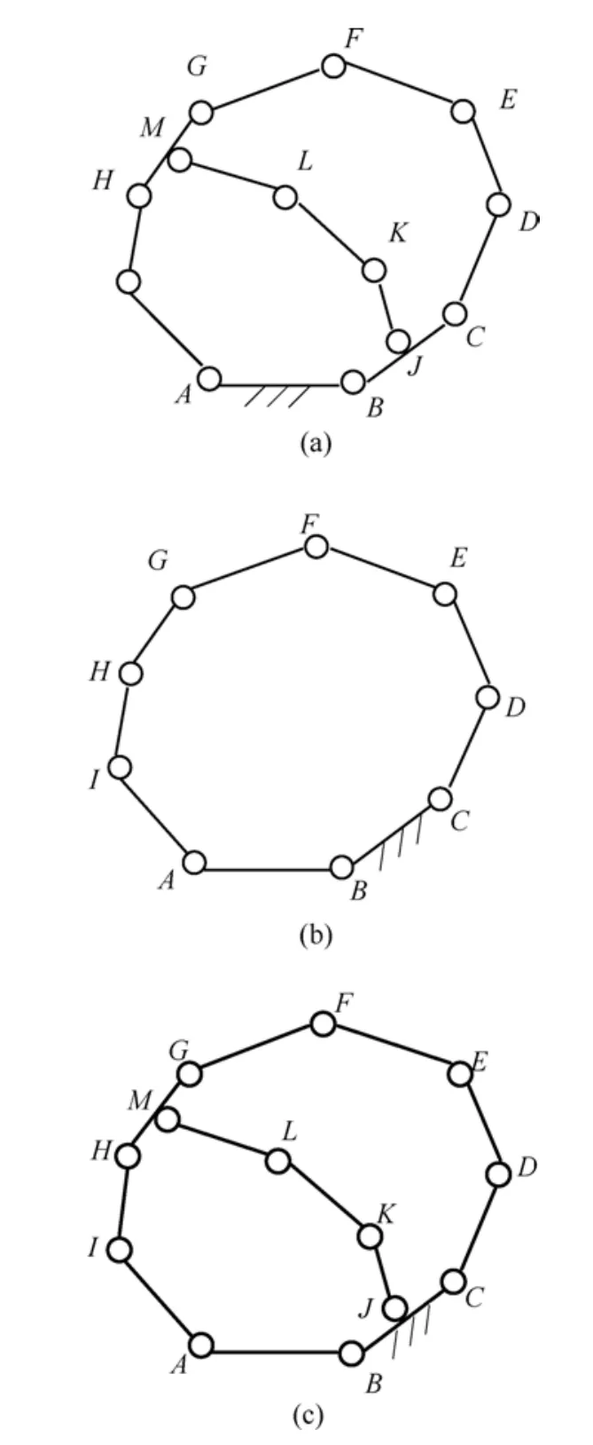
Fig.2.Over-constraints caused by dynamic closure
From the analysis above,over-constraints are caused in the closing process of the kinematic chains,and the motion state of the two connected components determines the closing type.Then corresponding analysis method may be selected.Lastly,by means of checking the relative movements between the two closing elements,the number and property of over-constraints can be certified,and then the mobility of the mechanism can be calculated by the following Eq.(6).
2.3 Complexity of mechanisms
The number of mechanism's independent-loop is directly relevant to the number of the closing process,which also determines the complexity of mechanism.For the complex mechanism,the number of independent-loop in mechanism can be determined by the Euler theorem:
whereldenotes the number of independent-loops.
According to the number of independent loops and the closure process,three categories are discussed as follows.
(1) Single loop closure in one time.Over-constraints in the single loop mechanism occur when the open serial kinematic chain of the corresponding single loop mechanism recloses.It is the simplest closure type.As shown in Fig.1,a serial chain is translated into a single closed loop mechanism by one closing process.So the over-constraints of the mechanism can be determined during the closing process.
Serial mechanisms are a serial rod-group connected with the frame,and the mobility of the end rod depends on the rank of its motion screw system.As theorem 3 describes,the reciprocal screw of the single-loop mechanisms reveals its over-constraints.For the sake of convenience,some relevant rules on how to determine the mobility of the serial chain and single closed loop mechanisms are given as follows:
(a) Serial chain has no over-constraints and its mobility is the sum of its kinematic pairs' mobilities.(b) For single loop mechanism (including planar mechanisms and spatial mechanisms),its reciprocal screw can be obtained by theorem 3 firstly,and then the mobility of the mechanism can be calculated directly using Eq.(6).
(2) Multi-loop closure in one time.For parallel mechanism,all its limbs simultaneously connect with the same up/down platforms and it forms the multi-loop mechanism.Because all loops in parallel mechanism are formed at the same time,this process is named as multi-loop closure in one time.This closure way,as an exceptional case,is easier than the closure patterns of GMSMs.The method to determine the over-constraints of parallel mechanisms has been solved,so it is not specified in this paper.
(3) Multi-loop closure in many times.Multi-loop mechanisms contain general planar mechanisms,spatial ones and more complicated spatial network ones.Usually those serial chains are translated into a multi-loop mechanism via multi-closing process,which also bring into many over-constraints correspondingly.This is the very general situation where over-constraints occur,and is also very complicated.For these mechanisms,it is necessary to study the over-constraints occurred in every closing process respectively.
The structure of the multi-loop mechanisms is very irregular.They consist of several serial chains,which are gradually connected with an initial single loop mechanism in different closure ways.The continuous procedure makes the mechanism bigger,and more complicated.In order to analyze its mobility,the mechanism should be decomposed and stratified in a successive way by an order firstly (see the following examples).Then reclose every open chain successively according to the order of the stratification before and check whether over-constraints occur.At last,calculate the number of over-constraints and obtain the mobility of the multi-loop mechanism by Eq.(6).
The mobility calculation depends on the distinction of the three closure patterns above.In order to analyze mobility of the general multi-loop mechanisms,a new principle about how to find the hidden over-constraints in these mechanisms will be introduced in section 3.
3 Universal Mobility Formula and Over-Constraint Recognition
3.1 Universal mobility formula
(1) Mechanism mobility formula
It is a key point for mobility analysis to accurately judge the over-constraint in a mechanism.Theoretically,the correct result can be acquired by considering the over-constraints,namely
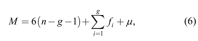
whereμdenotes the number of over-constraints.
(2) Mobility formula for a component
Different components in a single-loop multi-DOF mechanism have different DOFs.In order to obtain the corresponding mobility for a designated link in a loop,firstly,this multi-DOF mechanism can be considered as a parallel mechanism,and then take the discussed link as the moving platform,and lastly the initial problem has been translated into solving mobility of a parallel mechanism.
To be specific,after choosing the moving platform,the reciprocal screws of each branch connected with the moving platform have to be determined firstly.Then obtain the reciprocal screws for the whole moving platform and its rankσ.At last,the mobility of the moving platform can be obtained.So the mobility of the moving platform can be calculated according to the formula:
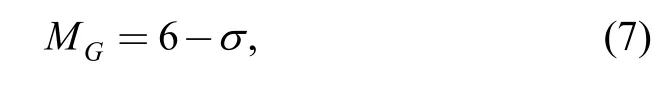
whereMGdenotes the mobility of the component;σthe number of independent reciprocal screws acting on the component.
Similarly,with the analysis of any component in complex multi-loop mechanism,its mobility can be obtained therefore.
3.2 Ways to recognize over-constraints
3.2.1 General principle
In order to determine the over-constraints of GMSMs,it is necessary to consider whether it has special geometrical demands firstly.There are lots of useful information to refer to,such as whether some a kinematic chain can constitute a parallelogram or not,whether the tracks of some a point coincide with each other,whether the distance between two points keeps constant and so on.Based on this the mechanisms can be simplified largely and the complex mechanisms can be decomposed into simple independent mechanisms,and the successive analysis can be undertaken then.
As previously mentioned,over-constraints of the first loop can be directly acquired according to theorem 3 and then its mobility can be obtained as well.However,motion coupling will absolutely happen from the second loop of the series loops,and goes stronger and stronger.This new issue makes the mobility analysis quite difficult.Then the mobility based on theorem 3 cannot be analyzed directly for any other loop.In order to solve the new difficult problem two corresponding methods to deal with the closing process are presented in this paper.
3.2.2 Method to recognize over-constraints by analyzing relative movement
In order to introduce the method to recognize the over-constraint of this general multi-loop spatial mechanism with motion coupling,an example will be given here to show this method.
As shown in Fig.3(a),it is an engine machine with a slant crank[46]and the mechanism is a spatial complex multi-loop one.The crankABdrives the slant turntableIBD,and one endpointCconnects with the frame by a sphere pair where the axis of rotational pairApasses through.On the other hand,the two endpointsH,Gof the turntableIBDare limited in a big circle slot with two pins,and then the turntable cannot rotate along the axisBC.In addition,the turntable connects with the sliderFby linkDEwith two spherical pairs.Another limbIJKwith the same structure also connects with the frame by a sliderK.When the crankABrotates,it drives the two slidersFandKto move left or right to complete its work.
Considering the circle slot,the spherical pairCand sliding pairsGandHform a compound pair,and they could be regarded as a sphere-pin pair,which only contains two rotational DOFs,namely,one about theZ-axis,the other about the directionGH.The structure diagram of the mechanism is shown in Fig.3(b).There are seven components in total,in whichACFKis the frame.There are nine kinematic pairs including 1 sphere-pin pair,four spherical pairs,two sliding pairsFandD,and two revolute pairs.
Based on the Euler theorem,independent loops of the mechanism can be determined by Eq.(5):
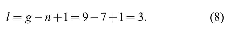
So,the mechanism includes three independent loops,which are closed loopsABCA,ABDEFAandABIJKA,respectively.It is a multi-loop mechanism and formed by several closing processes.In every closing process,over-constraints may be brought in.Now,the analysis of the first loopABCAis done initially.
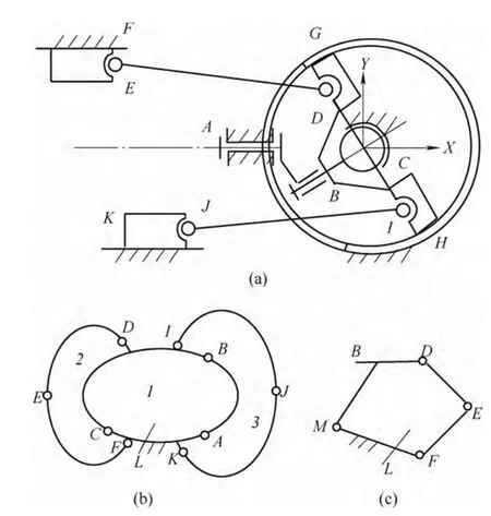
Fig.3.Engine with a slant crank
(1)ABCAis a single loop,which includes three components and three kinematic pairs,whereA,Bare rotational pairs,andCsphere-pin pair.The motion screws of the single loop are
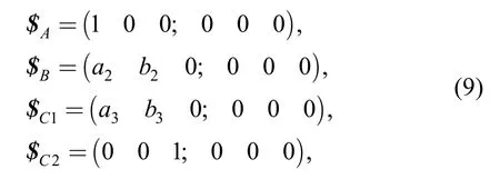
wherea2,a3,b2,andb3are real numbers.
Obviously,based on theorem 3,the rank of this motion screw system is three,and that is to say,it has three reciprocal screws,which also means three over-constraintsμ1=3,the mobility of the loop can be obtained by Eq.(6):
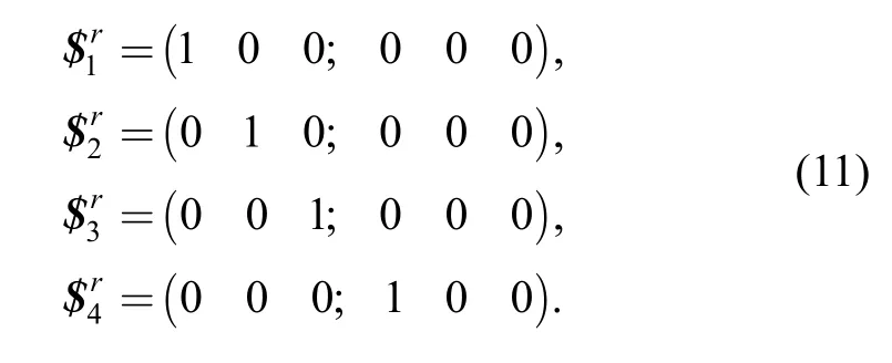
(2) Analyze mobility of theCBDlink.Now considering the over-constraints caused by the second closed loopABDEFA,because of the motion coupling between different loops,it must not directly take theorem 3 to calculate the over-constraint.It is necessary firstly to find out the connected link's motion and corresponding moving screws.That link should be chosen among various loops,and here the link is just the componentCBDbetween the first and second loops.Then use the motion screws including the screws of linkCBDto set a new screw system and further forms a new virtual closed loop.After that,open the new loop and reclose it,the relative motion between the two end of the new loop is needed to analyze.Hence,take componentCBDas the moving platform of an assumed parallel mechanismABCwhich possesses two limbs.The first limbABcontains kinematic pairsA,Band possesses two motion screwsand.The second limb has only one sphere-pin pairC,also corresponding to two motion screwsand.Their motion screws are described as Eq.(9).
Then the reciprocal screws of the first limb can be obtained:
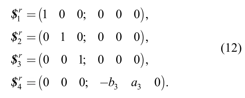
The reciprocal screws for the second limb are as follows:
There are eight constraint screws which are applied to the platformCBD.Only five of them are independent:
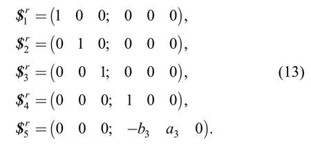
The reciprocal screw of Eq.(13) is as follows:
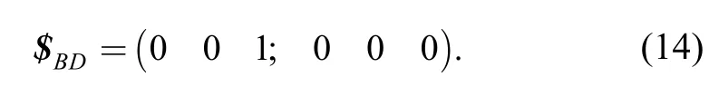
Eq.(14) shows the moving platformCBDonly has one DOF,which is rotation along theZ-axis and passes through pointC.
(3) Solve the over-constraints caused by the second closed loops.One needs open the second loop and reclose it again,then check the over-constraints during the reclosing process,meanwhile it needs to pay attention to consider the mobility of the link which is contained in the former and latter loops simultaneously.
In order to judge the existence of over-constraints during the closing process of the kinematic chain,detach frame at the cross sectionL,and the open kinematic chainBDEFLcan be obtained as Fig.3(b) shows.The motion of the open chain not only relates to pairsD,EandF,but also with componentCBDin the 1st loop.This is just the motion-coupling relationship between loops.The motion screw systems of the open chainBDEFLare as follows:
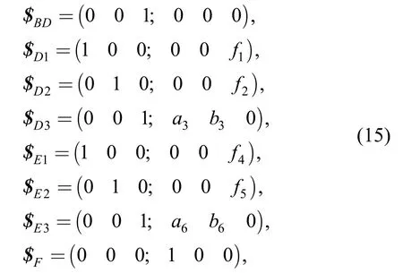
wheref1,f2,f4,f5,a6andb6are real numbers,which do not influence the results and need not to be calculated.
Obviously,the rank of Eq.(15) is six,which means the end link has six DOFs,including three translational and three rotational DOFs.When this open chain is reclosed again at the pointL,in general,the relative movements between the two closing components should be analyzed,respectively.The over-constraint may be obtained.
From the analysis the second closing here is a rigidity closure,which brings six constraints in.From the point of relative movements,the process of rigidity closure brings six constraints and restrains six DOFs of the end-rod of the serial chains correspondingly,so all of the six constraints can be defined as real constraint,and there is not any over-constraint for the second reclosing,namely,μ2=0 .This is the method to judge over-constraint by analyzing the relative movements between two closed elements.
The rigidity closure above is relative simple.As to the complex closing or more intricately dynamical closing,sometimes the analysis becomes even difficult,and a comparison table for determining the over-constraints may be applied to simplify the analysis at that situation (refer to the next part of the research work).
(4) Similarly,there is no over-constraint in the third closed loopABIJKAas well,namely,μ3=0 .
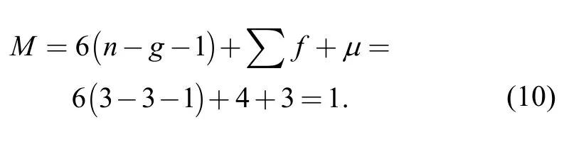
(5) The mechanism includes seven components,nine kinematic pairs.As mentioned above,the mechanism has three over-constraints,namely,μ=μ1+μ2+μ3=3,then
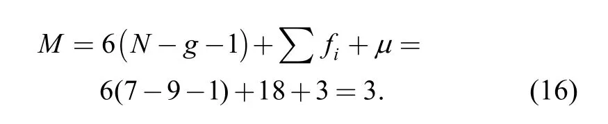
The mechanism contains three DOFs,including two local rotational DOFs (aboutEDandIJaxes,respectively),so the output mobility of the mechanism is one.
3.2.3 Method to recognize over-constraintsby virtual loop
With regard to multi-loop mechanisms,when it comes to solve the second loop or the other loops,there is another method to recognize the over-constraint i.e.using virtual loop.Here the mechanism in Fig.3 can also be taken as an example to demonstrate this method.
Dependent on the mobility of componentBD,which locates between the two loopsABCAandABDEFA,the rodBDcan be considered as directly connecting with frame by a virtual multi-DOF kinematic pairM.The motion screw system of rodBDis corresponding to that of the virtual pairM.A new closed loopMDEFMcould be obtained with the pairMand another 3 kinematic pairsD,EandF,which is named as the virtual loop.Obviously,this virtual loop can be used to replace the original second loopABDEFto analyze the over-constraints,as Fig.3(c) shows.This method is named as“method to recognize over-constraints by virtual loops”.As the former shows,the motion screws of this virtual loop are as follows:
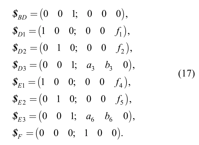
There are six independent screws in Eq.(17) and the rank is six.This also sufficiently illustrates that the virtual loop does not bring any over-constraint in,which coincides with the former conclusion,namely,μ2=0 .
By contrasting the two methods above,the first method can explain the emergence reason of over-constraints,but also shows its complexity,and the second method is simpler,but also has some limits.
4 Conclusions
From above analysis the conclusions can be summarized as follows:
(1) Three theorems are given which indicate no any over-constraint exits in serial chain unless the open chain close;and“how to analyze the over-constraints of a single-loop mechanism”by the screw theory.
(2) The open chain closings are divided into three types including the rigid closure,movable closure and dynamic closure,and this last one is the most complex and difficult situation.
(3) For GMSM,there exists motive coupling even strong motive coupling among its independent loops,and it makes over-constraint more complex to recognize.It needs to open all loops and reclose it one-by-one,and from each closure to recognize the over-constraints.
(4) Two common methods are proposed to solve the over-constraint for GMSMs with strong motive coupling,i.e.“recognizing over-constraints by analyzing relative movement”and“recognizing over-constraints by virtual loop”.The concept of the former method is clearer,and the latter is simpler.They form our mobility principle for the GMSMs.
(5) This principle complements enriches and develops the former universal mobility theory.
[1]HUANG Xikai,ZHENG Wenwei.Theory of machines and mechanisms[M].Beijing:People's Education Press,1981.(in Chinese)
[2]WANG Zhixing,LIU Tingrong.Theory of machines and mechanisms[M].Beijing:Higher Education Press,1999.(in Chinese)
[3]SUN Heng,CHEN Zuomo,GE Wenjie.Theory of machines and mechanisms[M].Beijing:Higher Education Press,2006.(in Chinese)
[4]JOHN J U,GORDON R P,JOSELPH E S.Theory of machines and mechanisms[M].New York:Oxford University,2003.
[5]GOGU G.Mobility of mechanisms:a critical review[J].Mechanism and Machine Theory,2005,40(9):1068-1097.
[6]ALTMANN F G.Special spatial coupling gears and its application[J].Construction Materials Experimentation,1952,4:97-106.(in German)
[7]BAKER J E.Overconstrained 5-bars with parallel adjacent joint axes[J].Mechanism and Machine Theory,1978,13:213-218.
[8]BAKER J E,DUCLONG T,KHOO P S H.On atempting to reduce undesirable characteristics of the schatz mechanism[J].Journal of Mechanical Design,1982,104:192-205.
[9]BENNETT G T.A new mechanism[J].Engineering,1903,76:777-778.
[10]BRICARD R.Theory of kinematics[M].Pairs:Gauthier-Villars,1927.(in French)
[11]DELASSUS E.The hinge systems.Part 1[J].Higher Science Specification,1900,17(3):455-499.(in French)
[12]DELASSUS E.The hinge systems.Part 2[J].Higher Science Specification,1900,19:119-152.(in French)
[13]ECKHARDT H D.Kinematic design of machines and mechanisms[M].New York:McGraw-Hill,1998.
[14]GOLDBERG M.New 5-bar and 6-bar linkages in three dimensions[J].Journal of Mechanical Design,1943,65:649-661.
[15]HERVÉ J M.Structure analyse of mechanisms with group displacement[J].Mechanism and Machine Theory,1978,13(4):437-450.(in French)
[16]HERVÉ J M.Foundation principle theory of mechanisms[J].Rev.Roum.Sci.Tech.,.1978,23 (5):693-709.(in French)
[17]MYARD F E.A geometrical contribution of the joints systems[J].Mathematics Society in France,1931,59:183-210.(in French)
[18]MABIE H H,REINHOLTZ C F.Mechanisms and dynamics of machinery[M].New York:John Wiley &Sons,1987.
[19]NORTON R L.Design of machinery:an introduction to the synthesis and analysis of mechanisms and machines[M].Boston:McGraw-Hill,1999.
[20]PHILLIPS J.Freedom in machinery introducing screw theory,vol.I[M].Cambridge:Cambridge University Press,1984.
[21]WALDRON K J.Overconstrained linkages[J].Environ.Plan,1979,2(6):393-402.
[22]CARRICATO M,PARENTI-CASTELLI V.Singularity-free fully isotropic translational parallel mechanism[J].International Journal of Robotics Research,2002,21(2):161-174.
[23]WENGER P,CHABLAT D.Kinematic analysis of a new parallel machine tool:the orthoglide[J].Advance in Robot Kinematics,2000,5:305-314.
[24]GOGU G.Structural synthesis of parallel robotic manipulators with decoupled motions[R].Report ROBEA MAX—CNRS,2003.
[25]CHEBYCHEV P A.Theory of parallelogram mechanisms,1st part[R].Submissions to the Imperial Academy of Sciences in St.Petersburg by various scholars,1854.(in Frence)
[26]HUNT K H,PHILLIPS J R.Kinematic mechanical connection for spatial movement[J].Mechanical Transmission,1965,14:657-664.(in German)
[27]HUNT K H.Kinematic geometry of mechanisms[M].Oxford:Oxford University Press,1978.
[28]WALDRON K J.The constraint analysis of mechanisms[J].Journal of Mechanisms,1966,1(2):101-114.
[29]BAGCI C.Degrees of freedom of motion in mechanisms[J].ASME Journal of Engineering for Industry,1971,93(1):140-148.
[30]DAVIES T H.Mechanical networks—I:passivity and redundancy[J].Mechanism and Machine Theory,1983,18(2):95-101.
[31]ZHANG Qixian.Analysis and synthesis of spatial manipulators(Volume1)[M].Beijing:China Machine Press.1984.(in Chinese)
[32]AGRAWAL V P,RAO J S.Fractionated freedom kinematic chains and mechanisms[J].Mechanism and Machine Theory,1987,22(2):125-130.
[33]ANGELES J,GOSSELIN C.Determination of the degree of freedom of simple and complex kinematic chains[J].Transactions of the Canadian Society for Mechanical Engineering,1988,12(4):219-226.(in French)
[34]ALIZADE R I.On degree of freedom of kinematic chain[J].Azerbaijan Polytech:Automation Design of Mechanisms,Manipulators and Robots,1988:3-14.
[35]TSAI L W.Robot analysis:the mechanics of serial and parallel manipulators[M].New York:John Wiley,1999.
[36]MCCARTHY J M.Geometric design of linkages[M].New York:Springer-Verlag,2000:3-8.
[37]WALDRON K J.Overconstrained linkages[J].Environment Plan,1979,6:393-402.
[38]RICO J M,GALLARDO J,RAVANI B.Lie algebra and the mobility of kinematic chains[J].Journal of Robotic Systems,2003,20(8):477-499.
[39]LIN J W,ZHANG J H,ZHANG C C,et al.Aero-engine blade fatigue analysis based on nonlinear continuum damage model using neural networks[J].Chinese Journal of Mechanical Engineering,2012,25(2):338-345.
[40]XU Yundou,YAO Jiantao,ZHAO Yongsheng.Kinematic analysis of a typical DDS forging manipulator[J].Journal of MechanicalEngineering,2012,48(3):50-56.
[41]XU Yundou YAO Jiantao ZHAO Yongsheng.Simple methods for distinguishing instantaneity of mobility of the overconstrained parallel mechanism based on the geometric constraint conditions[J].Journal of Mechanical Engineering,2013,49(5):10-16.
[42]BAKER J E.On relative freedom between links in kinematic chains with cross-jointing[J].Mechanism and Machine Theory,1980,15(5):397-413.
[43]HUANG Zhen,KONG Lingfu,FANG Yuefa.Mechanism theory of parallel robotic manipulator and control[M].Beijing:China Machine Press,1997.
[44]HUANG Zhen,LIU Jingfang,LI Yanwen.On the degree of freedom-the general formula of the degree of freedom which has been searched for 150 years[M].Beijing:Science Press,2011.
[45]HUANG Zhen,LI Qinchuan,DING Huafeng.Theory of parallel mechanisms[M].Dordrecht:Springer,2012.
[46]KOZHEVNIKOV C H,YESIPENKO Y I,RASKIN Y М.Mechanisms design manual[M].Moscow:Mechanical Engineering Press,1976.(in Russian)
Biographical notes
ZENG Daxing,born in 1978,is currently an associate professor atYanshan University,China.He received his PhD degree in mechatronic engineering atYanshan Universityin 2008.His research interests include parallel mechanism,type synthesis and image processing.
Tel:+86-335-8 059817;E-mail:roboms@ysu.edu.cn
LU Wenjuan,born in 1983,is currently a PhD candidate majored in mechatronics atYanshan University,China.She received her master degree on mechanical design and theory inYanshan Universityin 2008.Her research interests include parallel mechanism,type synthesis.
Tel:+86-335-8 059817;E-mail:wenjuan_lu@163.com
HUANG Zhen,born in 1936,is currently a professor and a PhD candidate supervisor atSchool of Mechanical Engineering,Yanshan University,China.His main research interests include parallel robot,type synthesis and topology.
Tel:+86-335-8 074709;E-mail:huangz@ysu.edu.cn
杂志排行
Chinese Journal of Mechanical Engineering的其它文章
- Improving Tribological Performance of Gray Cast Iron by Laser Peening in Dynamic Strain Aging Temperature Regime
- Determination of Elastoplastic Mechanical Properties of the Weld and Heat Affected Zone Metals in Tailor-Welded Blanks by Nanoindentation Test
- Effects of Driving Mode on the Performance of Multiple-Chamber Piezoelectric Pumps with Multiple Actuators