Parameters Optimizing of Ammonia-Recovery System in the Modified Equipment of Flax Fiber
2015-01-12MENGZiyi孟子义MENGZhuoRENGuobin任国斌SUNZhijun孙志军SUNYize孙以泽
MENG Zi-yi (孟子义), MENG Zhuo (孟 婥), REN Guo-bin (任国斌), SUN Zhi-jun (孙志军), SUN Yi-ze (孙以泽)
College of Mechanical Engineering, Donghua University, Shanghai 201620, China
Parameters Optimizing of Ammonia-Recovery System in the Modified Equipment of Flax Fiber
MENG Zi-yi (孟子义), MENG Zhuo (孟 婥)*, REN Guo-bin (任国斌), SUN Zhi-jun (孙志军), SUN Yi-ze (孙以泽)
CollegeofMechanicalEngineering,DonghuaUniversity,Shanghai201620,China
A detailed analysis of operational process and principle of ammonia-recovery system in the modified equipment of flax fiber, which will be applied to parameters optimizing of the ammonia-recovery system as a foundational principle, is presented. According to the principle, an ammonia compressor, whose working conditions are based on key operational parameters of the whole ammonia-recovery system, is the mainly energy-consumption part of ammonia-recovery system in the modified equipment of flax fiber. A generally mathematical model based on work efficiency of an ammonia compressor is founded, which is available to rate effective work and energy consumption of the ammonia compressor. The optimum operation-efficiency of the ammonia compressor is chosen as the goal to analyze and calculate the key operational parameters of the ammonia-recovery system. In the above analyzing and calculating, a mathematical model on ammonia flowing from the reactor to the register 1 is developed, in order to provide further understanding of the principle of an ammonia-recovery system. At the meantime, the ammonia flow regime in the pipeline and the process of ammonia inflation and deflation from the reactor to the register 1 are taken separately into account in the model. An iterative method is for obtaining parametric solutions of the mathematical model on ammonia flowing from the reactor to the register 1 and the key operational parameters of the ammonia-recovery system. A parametric analysis is put forward to complete showing the ammonia velocity or the state of the reactor and the register 1. The key optimized parameters will be achieved in term of the minimum efficiency after comparing the work efficiencies of an ammonia compressor at different working conditions.
ammonia-recoverysystem;parameteroptimizing;ammoniacompressor;workefficiency;charginganddischargingmodel
Introduction
Linen cloth,which is of good hygroscopicity and breathability, is beloved of customers. However, natural flax fiber, which has many shortcomings such as hard and brittle fiber, poor elasticity and crease resistance, can’t completely meet people’s high requirements. Liquid ammonia treatment could improve not only crease-resistant and shrinking rate, but also hygroscopicity and air permeability of linen fabrics[1]. Meanwhile, the treated linen fabrics by liquid ammonia has better bend-resistant. Therefore, the key technologies of the equipment of flax fiber modified by liquid ammonia should be studied urgently. The special characters of ammonia make reclaiming residual ammonia in the modified equipment of flax fiber become a crucial technique.
A great deal of research work about the ammonia-recovery process has been done by researchers[2-5]at home and abroad. However, improving ammonia-recovery rate caught most attention in the ammonia-recovery system. This paper reports on reducing energy consumption of the whole ammonia-recovery system via saving energy of mainly energy-consuming facilities in the operating process. A detailed analysis of operational process and principle of the ammonia-recovery system has been done in view of high-purity remaining ammonia in the modified equipment of flax fiber. The condensation and liquefaction must be completed in the range of pressure according to designed crafts of ammonia-recovery system in the equipment. The pressure of liquefaction is from ammonia compressors in the ammonia-recovery system. So ammonia compressors are the mainly energy-consuming installations in the system. If energy consumption of compressors could be decreased by means of optimizing operation of the ammonia-recovery system, energy consumption of the whole system would be lower. Therefore, a mathematical model of work efficiency of the ammonia compressor was developed to optimize its operation. As operational parameters of the ammonia-recovery system depending on the range of operational pressure of the register 1, a mathematical model of First Compression Stage was developed to calculate operational pressure range of the register 1. The operational pressure of register 1, which is the key operational parameter of the whole ammonia-recovery system, was achieved by means of numerical simulation. Likewise, the operational pressure of the register 2 was achieved to optimize operation of the front ammonia compressor.
1 Operational Principle of Ammonia-Recovery System in the Modified Equipment of Flax Fiber
Ammonia-recovery system in the modified equipment of flax fiber is shown in Fig.1. The whole system could be theoretically broken up into two parts with different functions of different parts.

Q—ball valve; J—cut-off valve; number (5, 9, 11, …)—serial number of valve in the systemFig.1 Ammonia-recovery system in the modified equipment of flax fiber
(1) First Compression Stage: this part consists of the front ammonia compressor, vacuum pump and the register 2. Its function is to provide stably suitable pressure and temperature for intake of the rear ammonia compressor.
(2) Second Compression Stage: this part consists of the register 1, the rear ammonia compressor, evaporative condenser and auxiliary storage. Its function is that ammonia from the register 1 is compressed to saturated vapor pressure or superheated steam pressure of ammonia at reasonable temperature by the rear ammonia compressor. Under this condition, the ammonia can be condensed into liquid ammonia in the evaporative condenser. Then, the liquid ammonia at normal temperature is reclaimed into auxiliary storage.
On the basis of analysis above, the register 1 is the key device and its operational pressure range has important influence on operations of other installations in the ammonia-recovery system, especially on the rear ammonia compressor. Therefore, for analyzing the pressure of register 1 easily, three running states shown in Fig.2 on First Compression Stage of ammonia-recovery system in the modified equipment of flex fiber can be described in the light of working pressure of the reactor.
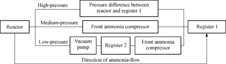
Fig.2 Running states of First Compression Stage in the ammonia-recovery system
(1) High-pressure state: there is the dynamic equilibrium process of ammonia gas-liquid transformation during ammonia pump exhausting liquid ammonia from the reactor. Ammonia of saturated steam, whose temperature is lower than that in the outside and pressure is about over 1 MPa, is full of the reactor, when the amount of liquid ammonia in the reactor is near null. This moment, the reactor pressure, is lower than the saturated vapor pressure of ammonia at room temperature, but is far higher than the register 1 pressure. Therefore, ammonia would flow spontaneously from reactor to register without any other assistance.
(2) Medium-pressure state: the pressure difference between the reactor and the register 1 would be smaller and smaller because of the ammonia flowing spontaneously from the reactor to the register 1. Ammonia flows from the reactor to the register 1 with assistance of the front ammonia compressor, when there is no pressure difference between them(the pressure difference is under 0.01 MPa).
(3) Low-pressure state: along with ammonia decreasing in the reactor, the reactor pressure will be lower than proposed intake pressure of the front ammonia compressor. At this moment, ammonia in reactor will be exhausted by vacuum pump to register 2. Ammonia in the register 2 is pumped by front ammonia compressor into the register 1, when pressure of the register 2 is appropriate.
After operational principle of the ammonia-recovery system is analyzed, the ammonia compressors are often used and provide power for ammonia flowing. At the meantime, the ammonia compressors also provide suitable pressure for ammonia condensing. We can conclude that ammonia compressors are mainly energy-consumption installations in the system. On the other way, inlet pressure of the ammonia compressor is almost equal to working pressure of the register. Therefore, pressures of registers have significant impact on working and energy consumption of ammonia compressors. The registers are key installations in the ammonia-recovery system. Consequently, a general mathematical model of ammonia compressor work efficiency is developed to weigh up the efficient utilization of energy by ammonia compressors and to optimize working pressures of the registers, which are parameters of the ammonia-recovery system, and to fit the best working conditions of ammonia compressors reducing energy consumption of the whole ammonia-recovery system.
2 Mathematical Model of Ammonia-Recovery System in the Modified Equipment of Flax Fiber
2.1 Mathematical model of ammonia-compressor work efficiency
Work efficiency of an ammonia compressor can be affected by many factors, for example, configuration of an ammonia compressor, characters of ammonia in different thermodynamic states, ammonia thermodynamic characters of ammonia when it is intake or outlet of ammonia compressor and so on. In the paper, the mathematical model of ammonia compressor work efficiency is developed in accordance with the selected compressor. Therefore, the configuration of the ammonia compressor and ammonia saturated vapor pressure are known and only working conditions of the maximum work efficiencyηmaxof the ammonia compressor is what we should attain.
Factors affecting on the ammonia compressor work efficiency[6]ηinvolve volumetric efficiencyηv, indicated efficiencyηi, mechanical efficiencyηmand electrical efficiencyηe.
(1) Volumetric efficiencyηvis ratio of actual to theoretical displacement about ammonia compressor and reflects effective utilization ratio of an ammonia compressor cylinder volume. Factors affecting volumetric efficiencyηvof an ammonia compressor mostly include clearance coefficientλv, pressure coefficientλp, preheating coefficientλtand leakage coefficientλl. Therefore, the volumetric efficiencyηvis:
ηv=λvλpλtλl.
(1)
But the accurate solutions of four coefficients in Eq. (1) are very difficult to verify at different working conditions[7-9]. Consequently, usually empirical Eq. (2) is selected[10]in the paper to attain the volumetric efficiencyηv.
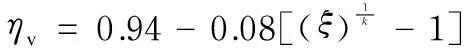
(2)
whereξis pressure ratio;k, which is 1.28, is the polytropic exponent of ammonia.
(2) Indicated efficiencyηiis ratio of theoretical to indicated power about ammonia compressor and reflects thermodynamic perfect degree of an ammonia compressor. Factors affecting indicated efficiencyηiof an ammonia compressor mostly include pressure ratioξ, relative clearance volumeδ0, preheating coefficientλtand leakage coefficientλl. Therefore, indicated efficiencyηi[11]is:
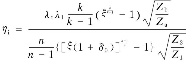
(3)
wherenis adiabatic exponent of ammonia;k, which is 1.28, is the polytropic exponent of ammonia;Zais ammonia compressibility factor in the theoretical intake state a of an ammonia compressor;Zbindicates ammonia compressibility factor in the theoretical outlet state b of an ammonia compressor;Z1indicates ammonia compressibility factor in the actual intake state 1 of an ammonia compressor;Z2indicates ammonia compressibility factor in the actual outlet state 2 of an ammonia compressor.
(3) Mechanical efficiencyηmis ratio of indicated to shaft power about an ammonia compressor and reflects power ratio of transmission gear in compressor. Friction loss of transmission gear in the selected ammonia compressor increases with pressure ratioξdecreasing. Therefore, mechanical efficiency of the ammonia compressor is inversely proportional to its pressure ratioξ.
(4) Electrical efficiencyηeis ratio of shaft to power of motor about an ammonia compressor and reflects effective work of motor in an ammonia compressor at different working conditions. Electrical efficiency of the selected ammonia compressor changes little at certain working conditions. As a matter of experience[12], electrical efficiencyηeof the selected ammonia compressor is 0.95.
Mostly affected factors about work efficiency of an ammonia compressor indicate efficiency of energy transfer during the compressor operating. Consequently, the mathematical model of work efficiencyηof the selected ammonia compressor in the paper is:
η=ηvηiηmηe.
(4)
2.2 Mathematical model of First Compression Stage in the ammonia-recovery system
First Compression Stage in the ammonia-recovery system is simplified in accordance with the fluid mass balance principle. We got the logistic model as shown in Fig.3.The pressure of the register 1 is:
p=F(p1, p2, p3)-Δp,
(5)
wherep1is pressure of the register 1 in high-pressure state, Pa;p2is pressure of the register 1 in medium-pressure state, Pa;p3is pressure of register 1 in low-pressure state, Pa; Δp is pressure difference in the register 1 after ammonia pumped by the rear ammonia compressor, Pa;Fis coupling relationship of the register 1 pressure in three states.
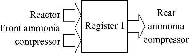
Fig.3 Logical model of First Compression Stage
(1) In the high-pressure state, ammonia flow spontaneously from the reactor to the register 1 under pressure difference. This process can be regarded as adiabatic degassing of the reactor and adiabatic charging of the register 1[13].
According to the law of conservation of mass and the first law of thermodynamics, the mass of ammonia degassing from the reactor is:
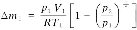
(6)
where Δm1is mass of degassing ammonia from reactor, kg;p1is pressure of the reactor before degassing, Pa;p2is pressure of the reactor after degassing, Pa;V1is volume of the reactor, m3;T1is temperature of the reactor before degassing, K;Ris constant of proportionality, J·(mol·K)-1;nis adiabatic exponent of ammonia.
Temperature of the reactor after degassing is:

(7)
whereT1is temperature of the reactor before degassing, K;T2is temperature of the reactor after degassing, K.
The mass of ammonia charging into the register 1 is:

(8)
where Δm2is mass of ammonia charging into the register 1, kg;p3is pressure of the register 1 before charging, Pa;p4is pressure of the register 1 after charging, Pa;V2is volume of the register 1, m3;T3is temperature of the register 1 before charging, K;T4is temperature of the register 1 after charging, K.
Temperature of the Register 1 after charging is:
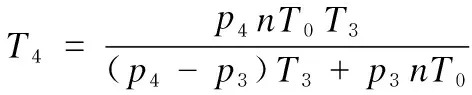
(9)
whereT0is temperature of ammonia from supply, K.
In the high-pressure state, when ammonia flow spontaneously from the reactor to the register 1 and the process ends in equilibrium,p2is equal top4and Δm1=Δm2.
(2) When ammonia flow through the pipeline, it is forced by differential pressure from ends of pipeline and drag force from pipe wall. Therefore, ammonia flowing through the pipeline can be seen as flowing state between adiabatic and isothermal[14]. Relation of ammonia current speed to the pressure from ends of pipeline is:

(10)

(3) Mass velocity of the ammonia compressor is concerned with thermodynamic state of intake ammonia. Mass velocity of the ammonia compressor, in accordance with volumetric flow of ammonia compressor and gas equation, is:
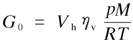
(11)
whereG0is mass velocity of ammonia compressor, kg·s-1;Vhis theoretical flowing capacity of ammonia compressor, m3·s-1;pis intake pressure of the ammonia compressor, Pa;Tis intake ammonia temperature of ammonia compressor, K;ηvis volumetric efficiency of ammonia compressor;Mis molar mass of ammonia, kg·mol-1.
3 Running Parameters Optimizing of Ammonia-Recovery System in the Modified Equipment of Flax Fiber
According to the principle and process of the ammonia-recovery system above, inlet pressure of the rear ammonia compressor is equal to pressure of the register 1 without pressure drop of pipeline. In the light of crafts of the ammonia-recovery system, the outlet pressure of the rear ammonia compressor is saturated vapor pressure of ammonia or above. compression ratio of the rear ammonia compressor mainly depends on working pressure of the register 1. Likewise, compression ratio of the front ammonia compressor almost depends on working pressure of the register 2. Therefore, optimizing the operational parameters of the ammonia-recovery system is to calculate appropriately operational pressure range to make sure that the ammonia compressors work at the best working conditions.
Thermal effects to an ammonia compressors could be neglected, when the optimum working condition of the ammonia compressor is discussed, because ammonia-recovery system in the modified equipment of flex fiber runs at normal temperature (20±2)℃. So, we assume that ammonia compressors run at constant temperature (20℃). Consequently, pressure ratioξwould be the mainly considering factor affecting ammonia operation-efficiencyη. There is difference in displacement and outlet pressure between the front and rear ammonia compressors. Therefore, the relationship of pressure ratio to ammonia operation-efficiency will help us to analyze the best ammonia compressor operation-efficiency of both front and rear ammonia compressors.
(1) During ammonia compressor operation-efficiency is calculated, some of parameters, which have influence on operation-efficiency, are shown in Table 1 from information of the front and rear ammonia compressor.
Table 1 Parameter about ammonia compressor operation. efficiency
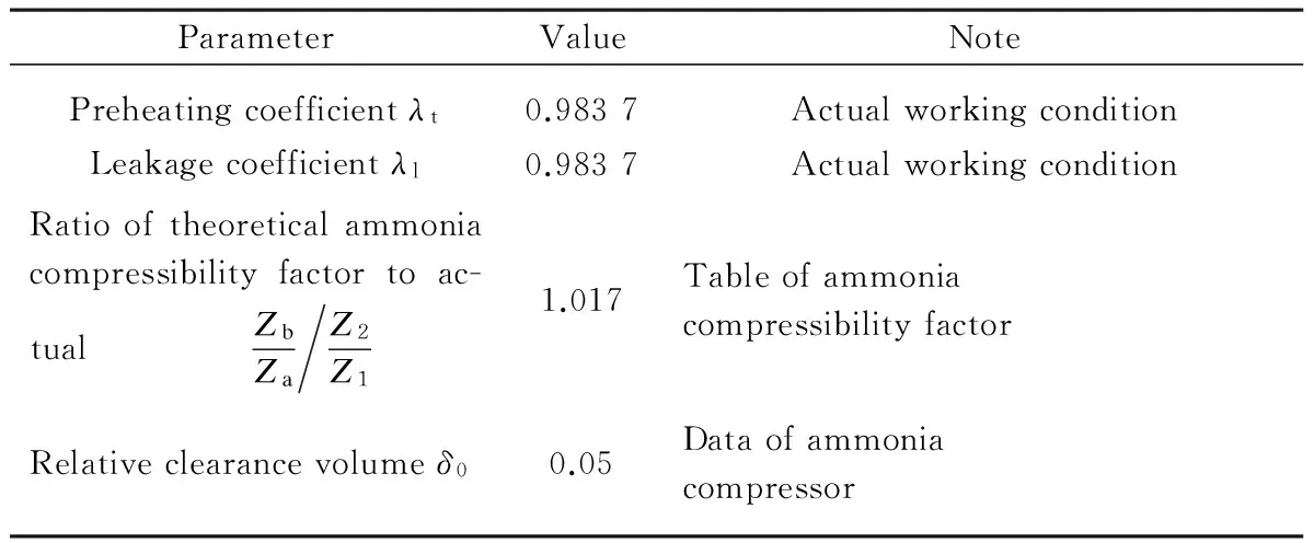
ParameterValueNotePreheatingcoefficientλt0.9837ActualworkingconditionLeakagecoefficientλl0.9837ActualworkingconditionRatiooftheoreticalammoniacompressibilityfactortoac-tual ZbZaZ2Z11.017TableofammoniacompressibilityfactorRelativeclearancevolumeδ00.05Dataofammoniacompressor
According to the mathematical model of the ammonia compressor working efficiency and graph of mechanical efficiency from Ref. [11], the relationship of ammonia compressor operation-efficiency ηtocompressionratioξisdescribedinFig.4.

Fig.4 Relation of ammonia compressor operation-efficiency to compression ratio
(2)Alldataaboutinstallationsofammonia-recoverysystemareshowninTable2.Theinitialtemperaturesofbothreactorandregister1are294.15K.Highpressurepartofpipelineisconnectedtothereactorandlowpressureisconnectedtotheregister1.Inthelightofcalculatingmathematicalmodelofammoniaflowingbetweenthereactorandtheregister1Eqs. (6)-(9)andammoniaflowinginpipelineEq. (10),pressuresofreactorandregister1andmassvelocityofammoniainthepipeline,areshowninTable3.
Table 2 Parameter of installations in the ammonia-recovery system

ParameterValueInitialpressureofreactor/MPa1Volumeofreactor/m31Numberofreactor5Initialpressureoftheregister1/MPa0Volumeoftheregister1/m35Distanceofpipeline/m5Diameterofpipeline/m0.04
Table 3 Pressure of reactor/register 1 and mass velocity of pipeline
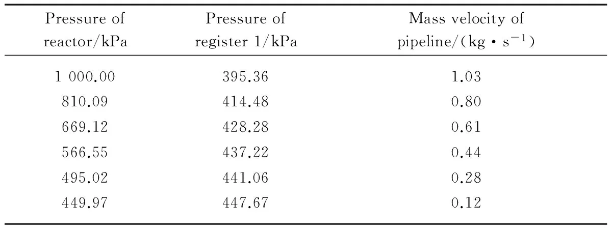
Pressureofreactor/kPaPressureofregister1/kPaMassvelocityofpipeline/(kg·s-1)1000.00395.361.03810.09414.480.80669.12428.280.61566.55437.220.44495.02441.060.28449.97447.670.12
(3) The data about the selected ammonia compressors are shown in Table 4. On the basis of the mathematical model of mass velocity Eq. (11) and volumetric flow of the selected ammonia compressors, mass velocity of the ammonia compressors, which are shown in Figs.5 and 6, are calculated under specified inlet pressures of them.
Table 4 Parameters of the selected ammonia compressors

ParameteroftheselectedammoniacompressorValueRatedvolumetricflowofthefrontammoniacom-pressor/(m3·min-1)0.5Specifiedinletpressureofthefrontammoniacom-pressor/MPa0.00.6Ratedvolumetricflowoftherearammoniacom-pressor/(m3·min-1)0.4Specifiedinletpressureoftherearammoniacom-pressor/MPa0.02.0
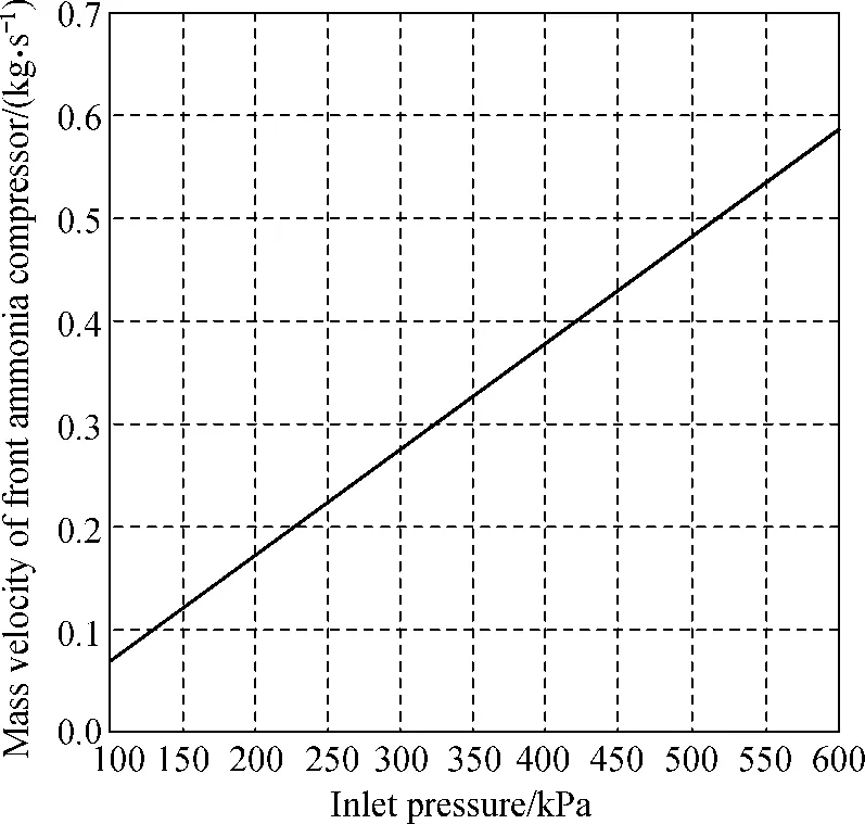
Fig.5 Mass velocity of the front ammonia compressor

Fig.6 Mass velocity of the rear ammonia compressor
(4) As shown in Fig.4, when compression ratio is 1.8-5.0, ammonia compressor work efficiency is optimum and total fruitless consumptions are low. Therefore, the optimum working pressure of the register 1 preliminarily is 0.4-1.0 MPa and of the register 2 is 0.12-0.30 MPa in accordance with optimum work efficiencies of ammonia compressor and the selected ammonia compressors. When ammonia compressors start working, ammonia mass flowing in and out of register should be almost the same to make sure that ammonia compressors can work in the best working condition. Finally, the optimum working range of the register 1 is 0.4-0.5 MPa after overall consideration of the mass velocity of ammonia flowing in pipeline shown in Table 3, of the front ammonia compressor shown in Fig.5, and of the rear ammonia compressor shown in Fig.6. When the pressure of the register 1 is above 0.4 MPa, the rear ammonia compressor should work continuously. As the mass velocity of inlet of the register 1 is almost equal to its outlet, when the intake pressure of the rear ammonia compressor is 0.4 MPa, the consumption of futile power is low according to Fig.4. At the same time, the rear ammonia compressor work continuously to avoid extra power consumption of starting compressor repeatedly. A function of the front ammonia compressor is to pump the low-pressure ammonia in the reactor and the register 2. Therefore, starting of the front compressor should be not frequent and its work condition should be perfect. The working pressure range of the register 2 is 0.1-0.2 MPa. When the pressure of the register 2 is above 0.2 MPa, the front ammonia compressor will pump ammonia from the register 2 until its pressure is under 0.1 MPa.
4 Conclusions
(1) Detailed analyses of operational process and principle of ammonia-recovery system in the modified equipment of flax fiber, which is applied to optimization analysis of the ammonia-recovery system as the foundational principle, are presented.
(2) Mathematical model of work efficiency of ammonia compressor is proposed to evaluate the energy consumption of ammonia compressor.
(3) Mathematical model of First Compression Stage in the ammonia-recovery system is developed in order to achieve operational parameters of the ammonia-recovery system. The optimum work efficiency of ammonia compressor is used to calculate registers 1 and 2 operational pressure ranges. At the meantime, key parameters of the ammonia-recovery system are optimized and the energy consumption is reduced.
[1] Feng J H, Zhang H, Li J. Wear ability of Linen Fabrics after Liquid Ammonia/Crosslinking Treatment [J].JournalofTextileResearch, 2008, 29(8): 63-66.(in Chinese)
[2] Zhang H, Zhao H L, Feng S B. Advances in Processes for Ammonia Recovery[C]. Chinese Annual Conference on Process Systems Engineering in 2009, Hangzhou, China, 2009: 125-128. (in Chinese)
[3] Ventas R, Vereda C, Lecuona A,etal. Experimental Study of a Thermo-Chemical Compressor for an Absorption/Compression Hybrid Cycle [J].AppliedEnergy, 2012, 97: 297-304.
[4] Wang B M, Wu H G, Li J F,etal. Experimental Investigation on the Performance of NH3/CO2Cascade Refrigeration System with Twin-Screw Compressor [J].InternationalJournalofRefrigeration, 2009, 32(6): 1358-1365.
[5] Meng X L, Zheng D X, Wang J Z,etal. Energy Saving Mechanism Analysis of the Absorption Compression Hybrid Refrigeration Cycle [J].RenewableEnergy, 2013, 57: 43-50.
[6] Wang G B. Determination of Property Parameters for Reciprocating Compressor [J].ProcessEquipment&Piping, 2005, 42(3): 44-47. (in Chinese)
[7] Chen R D, Yue X F. Refrigeration Technology and Application[M]. Shanghai: Tongji University Press, 2006: 39-49. (in Chinese).
[8] Wang J, Wang Y Y. Investigation on the Volumetric Efficiency of Automotive Air-Conditioning Compressor [J].FluidMachinery, 1994, 22(8): 53-56, 63.(in Chinese)
[9] Liang Y, Shi L. Simulation of Compressor of Automobile Air Conditioners [J].JournalofTsinghuaUniversity:Science&Technology, 1999, 39(11): 79-82.
[10] Shen X, Wang X Y, Huang Y J,etal. Thermodynamic Performance of Refrigeration Compressor Running at Variable Condition [J].JournalofRefrigeration, 2009, 30(6): 15-19.(in Chinese)
[11] Miao D P. Piston Refrigerant Compressor[M]. Beijing: China Machine Press, 1983: 5-45.(in Chinese)
[12] Yao J, Chen Z J. Prediction of Optimal Operation Point for Hermetically Sealed Piston Type Compressor with Simulation Program[C]. Annual Conference on Shanghai Institute of Refrigeration, Shanghai, China, 1989. (in Chinese)
[13] Qi M Z. Analysis of Energy in Chemical Engineering[M]. Shanghai: East China University of Science and Technology Press, 2009: 20-40.(in Chinese)
[14] Chen M H, Cong D Z, Fang T A,etal. Principles of Chemical Industry[M]. Beijing: Chemical Industry Press, 2006: 20-46.(in Chinese)
Foundation items: National Science and Technology Support Program, China (No. 2012BAF13B03); Program of Shanghai Subject Chief Scientist, China (No. 12XD1420300)
TS195.3 Document code: A
1672-5220(2015)01-0068-05
Received date: 2013-10-09
* Correspondence should be addressed to MENG Zhuo, E-mail: mz@dhu.edu.cn
杂志排行

Journal of Donghua University(English Edition)的其它文章
- Joint Optimization Strategy for Video Transmission over Distributed Cognitive Radio Networks
- Asymptotic Behavior of the Drift Coefficient Estimator of Stochastic Differential Equations Driven by Small Noises
- Adaptive Modulation and Coding Based on Fuzzy Logic Cognitive Engine
- Modeling and Simulation of P-Aloha, CSMA/CA and MACAW Protocols for Underwater Acoustic Channel
- Design and Analysis of Axial Thrust Roller-Exciting Vibrating Table and Its Motor-Control System Based on Co-simulation
- Effects of Compression Garments on Lower Limb Muscle Activation via Electromyography Analysis during Running