Analysis on Nipper Balance Shaft Movement with Transmission Drive of Comber
2015-01-12LIXinrong李新荣JIANGXiuming蒋秀明YANGJiancheng杨建成WANGXiaowei王晓维
LI Xin-rong (李新荣), JIANG Xiu-ming (蒋秀明), YANG Jian-cheng (杨建成), WANG Xiao-wei (王晓维)
School of Mechanical Engineering, Tianjin Polytechnic University, Tianjin 300387, China
Analysis on Nipper Balance Shaft Movement with Transmission Drive of Comber
LI Xin-rong (李新荣)*, JIANG Xiu-ming (蒋秀明), YANG Jian-cheng (杨建成), WANG Xiao-wei (王晓维)
SchoolofMechanicalEngineering,TianjinPolytechnicUniversity,Tianjin300387,China
The alternating movement of comber nipper balance shaft causes comber vibration, which is considered as the primary limitation for its velocity. First, optimal angular acceleration coefficients of nipper balance shaft were set in this study to acquire theoretical limiting angular velocity. Second, the transmission input model of the input shaft was developed by adopting a numerical approximation method and by considering the Bézier curve as the motion curve of the input shaft. Hence, the motion of nipper balance shaft was controlled. The optimum transmission driver curve of the input shaft was obtained by contrasting the analyses of the actual angular acceleration of nipper balance shaft for each optimal coefficient. Experimental tests validated the results. The nipper balance shaft of the comber reduced comber vibration because the shaft adopted the controllable unit of transmission input. Our research sheds light on the application of controlled mechanisms in textile machines and provides a theoretical basis for increasing the velocity and decreasing the vibration or noise of the comber.
transmissioninput;nipperbalanceshaft;vibration;Béziercurve
Introduction
Improvements of cotton-combing equipment in textile industry and extensively used computer technology for mechanical products make the design of high-speed cotton comber necessary[1]. Nipper balance shaft in high-speed reciprocating motion generates a great inertia force. Comber vibration resulting in noise and fatigue limits comber velocity. Recent research in cotton combers has reduced comber vibration by increasing the crank length of nipper balance shaft to increase comber velocity[2-5]. However, crank length cannot be diminished further considering the characteristics of nipper balance shaft. Therefore, it is necessary to develop a new design for solving this problem. Yanetal. proposed a transmission speed method to improve the dynamic characteristics of the mechanism, where he integrated traditional institutions and servo system to provide a modest flexible output in controlling the system of a traditional rigid body. Moreover, they fully integrated design and control measures to alternate rigidity with flexibility to obtain a machine with high speed and precision as well as low vibration[6-11].
Our study aims at solving the problem that the nipper balance shaft in high-speed reciprocating motion produces comber vibration. The transmission control mechanism was adopted as input, the ordinary constant speed motor was replaced with servo motor, the movement of nipper balance shaft was optimized, and the vibration of the comber was decreased by controlling the output of the servo motor without changing the technological parameters of the cotton comber. The nipper balance shaft was simplified, along with its kinematic model of the input shaft, based on isomeric principle.
The angular acceleration and angular velocity of the input shaft can be reversed by setting optimal coefficient. The Bézier curve was set as the motion curve of the input shaft by numerical approximation. The transmission input model of the input shaft was developed by contrasting the analyses of the angular acceleration of the nipper balance shaft for each optimal coefficient to obtain the optimum transmission driver curve of the input shaft. The results verified that adoption of the transmission drive of the input shaft decreased the vibration and noise of the comber caused by the nipper balance shaft.
In this study, the nipper balance shaft of the cotton comber using transmission input drive decreased comber vibration efficiently, demonstrating the feasibility and effectiveness of using transmission input to improve the dynamic characteristics and mechanical properties of the proposed method. This research sheds light on the application of controlled mechanisms in textile machines and offers a theoretical basis for increasing velocity and decreasing the vibration or noise of a comber.
1 Analysis and Optimization of Nipper Balance Shaft Mechanism
1.1 Simplification of nipper balance shaft mechanism
First, the nipper balance shaft of a cotton comber is analyzed (Fig.1) and its mechanism is simplified by using isomeric principle (Fig.2)[12]. As shown in Fig.2, the input shaft (1) drove the crank (2) and the guide block (3), which, in turn, drove the guide rod (4), thus forming the nipper balance shaft (5). The distance from the nipper balance shaft to the input shaft was set asL0(mm); the length of the crank (2) wasL1(mm); the displacement of the guide block (3) relative to the guide rod (4) wasL2(mm); for the angular displacement of the crank (2), the input shaft wasθ1, the angular velocity wasω1, and the angular acceleration wasα1; for the nipper balance shaft (5), the guide rod wasθ3, the angular velocity wasω3, and the angular acceleration wasα3.

1-input shaft; 2-crank; 3-guide block; 4-guide rod; 5-nipper balance shaft;Ⅰ-the first location of the nipper; Ⅱ-the last location of the nipperFig.1 The mechanism of the nipper balance shaft of cotton comber

Fig.2 Diagram of the mechanism of the nipper balance shaft of the cotton comber
1.2 Analyzing nipper balance shaft mechanism
As shown in Fig.2, Eq. (1) was obtained by using the vector direction ofOAB:
L0=L1ei θ1+L2ei(180-θ3).
(1)
Equation (2) was obtained by decomposing Eq. (1) on two axes, that is:
(2)
Equations (3) and (4) were obtained by analyzing the triangleOAB

(3)
(4)
Equation(5) was obtained by taking the derivative of Eq. (1) as follows:
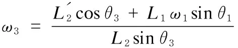
(5)
Equation (6) was obtained by taking the second derivative of Eq. (1) as follows:

(6)
1.3 Optimal analysis of the movement of the nipper balance shaft mechanism
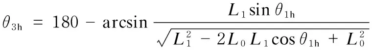
This study adopted a new nipper balance shaft mechanism driven by a servo motor, which decreased the effect of the nipper balance shaft on the first and last nipper positions, and improved the properties of the nipper balance shaft mechanism. As shown in Fig.2, Ⅰ was the first location of the nipper balance shaft, and the angular displacement of the input shaftθ1wasθ1q; Ⅱ was the last location of the nipper balance shaft, and the angular displacement of the input shaftθ1wasθ1h.θ1qandθ1hwere obtained from the following formulas:
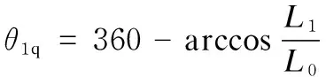
(7)

(8)
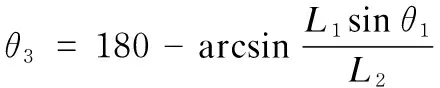
The angular displacementsθ3qandθ3h, corresponding to the first and last locations, respectively, were obtained using Eqs. (3) and (4), as follows:

(9)
(10)
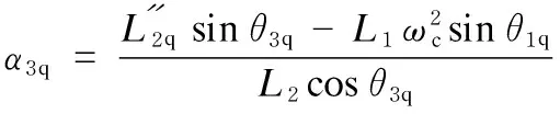
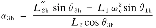
The angular accelerations of the nipper balance shaftα3qandα3h, corresponding to the first and last locations, respectively, were obtained using Eq. (6):

(11)

(12)
whereα1qandα1hwere the angular accelerations of the input shaft corresponding to the first and last locations of the nipper balance shaft, respectively. The angular velocity of the input shaft was set as a constant, such that the angular accelerationsα1qandα1hwere equal to zero; the velocity of the comber wasN; the angular velocity wasωc;ω1qandω1hwere the angular velocities of the input shaft corresponding to the first and last locations, respectively, of the nipper balance shaft, the value of which wasωc. Based on the cotton comber process,ω3qandω3hwere the angular velocities corresponding to the first and last locations of the nipper balance shaft, the values of which were both 0. Equations (13) and (14) were obtained by simplifying Eqs. (11) and (12):
(13)
(14)
The effect of the cotton comber was decreased by adjusting the angular accelerations on the first and last locations of the nipper balanceshaft. Thus, the low effect of the comber could be achieved with high velocity. The optimal coefficient of the first and last locations was set askin the following formulas:
αq=kα3q,
(15)
αh=kα3h,
(16)
whereαqandαhwere the optimized angular accelerations corresponding to the first and last locations of the nipper balance shaft respectively; andα3qandα3hwere the unoptimized angular accelerations corresponding to the first and last locations, respectively, of the nipper balance shaft.ωqandωhwere obtained by Eqs. (13) and (14):
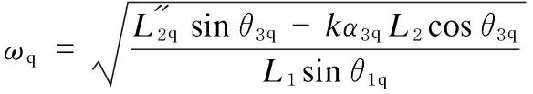
(17)
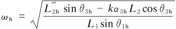
(18)
whereωqandωhwere the optimized theoretical angular velocities of the input shaft corresponding to the first and last locations of the nipper balance shaft, respectively.
1.4 Mathematical model of the motion trajectory of the input shaft
The new nipper balance shaft mechanism requires restraining the movement curve of the input shaft and improving the kinetic characteristics of the nipper balance shaft by adjusting the control point. The Bézier curve is a characteristic curve based on numerical approximation method, and the shape of this curve is only associated with the location of the control points. The curve satisfies the requirements of the mechanism motion trajectory curve. Therefore, the Bézier curve for the trajectories of the input shaft was adopted.
As shown in Fig.2, when the input shaft adopted a servo motor as the transmission input according to the Bézier curve, the angular displacement wasθ1y; the angular velocity wasω1y; the angular acceleration wasα1y; and the angular displacement of the nipper balance shaft,i.e., the guide rod wasθ3y, the angular velocity wasω3y, and the angular acceleration wasα3y. The angular velocity of the input shaftω1y(t)was defined as thentimes Bézier curve, as follows:

(19)

This study focused on optimizing the kinetic characteristics on the first and last locations of the nipper.The time of the Bézier curve was set as 3, and the design variable as P=[P0, P1, P2, P3], where the coordinates ofPwere (θ1,ω1) andθ1y∈[0, 2π].
The coordinates of the input shaft initial pointP0was set as (0,ω); the coordinates of last location of the nipperP1as (θ1h,ωh);P1ywas the actual optimized point ofP1; the coordinates of the first location of the nipperP2were (θ1q,ωq);P2ywas the actual optimized point ofP2; the coordinates of the end of the cycleP3were (2π,ω); andωwas the angular velocity at the beginning and end of the input shaft. Based on computer graphics principle, the transmission input model of the input shaft was developed as follows[13]:
θ1y=3t(1-t)2θ1h+3t2(1-t)θ1q+2πt3,
(20)
ω1y=(1-t)3ω+3t(1-t)2ωh+3t2(1-t)ωq+t3ω.
(21)
This study set the velocity of the comber asN, and the relation between the angular velocityωcand the velocity of the comberNwas defined as follows:
(22)
The following formula was obtained to make the average velocity before and after the change in input shaft speed equal:
(23)
By substituting Eq. (23) into Eqs. (20) and (21), the movement curve of the angular displacement of the input shaftθ1ywith the angular displacement of the nipper balance shaftω1ywas obtained, as shown in Fig.3.

Fig.3 Movement relation between the angular displacement θ1y of the input shaft and the angular displacement of the nipper balance shaft ω1y
As shown in Fig.3, the coordinates of the first location of the nipperP1was as (θ1q,ωq);P1ywas the actual optimized point ofP1and its coordinate was (θ1q,ωqy); the coordinates of the last location of the nipperP2as (θ1h,ωh);P2ywas the actual optimized point ofP2and its coordinate was (θ1h,ωhy).The result showed that the input angular displacement on the first and last location was never changed when optimizing the angular velocity of nipper. The traditional nipper balance and the cylinder shaft were synchronized. Moreover, the movement period of comber was determined by the cylinder shaft.In conclusions, when optimizing the angular velocity of nipper the first and last location of nipper, the movement period of comber were unchanged. It proves that the optimal method can meet the requirement of comber processing.
2 Validation and Analysis
2.1 Optimizing example
Taking the Rieter E62 comber of Swiss as an example,L0= 207 (mm),L1= 65 (mm), and comber velocity was 400 nips/min. By analyzing the input shaft that adopted a servo motor transmission input based on the Bézier curve, the values ofωc,ω,ωhandωqwere obtained using Eqs. (17), (18), (22) and (23), respectively. The values ofθ1yandω1ywere obtained by substituting these values into Eqs. (20) and (21), the value ofα3ywas obtained by substitutingθ1yandω1yinto Eqs. (5) and (6). The optimal coefficientkfrom 0.1 to 1.0 (k= 1.0 indicated that the input velocity was constant) resulted in the movement relation of the angular displacementθ1yof the input shaft with the angular accelerations of the nipper balance shaftα3y, as shown in Fig.4.

Fig.4 Movement relation between the angular accelerations θ1y of the input shaft and the angular displacement of the nipper balance shaft α3y
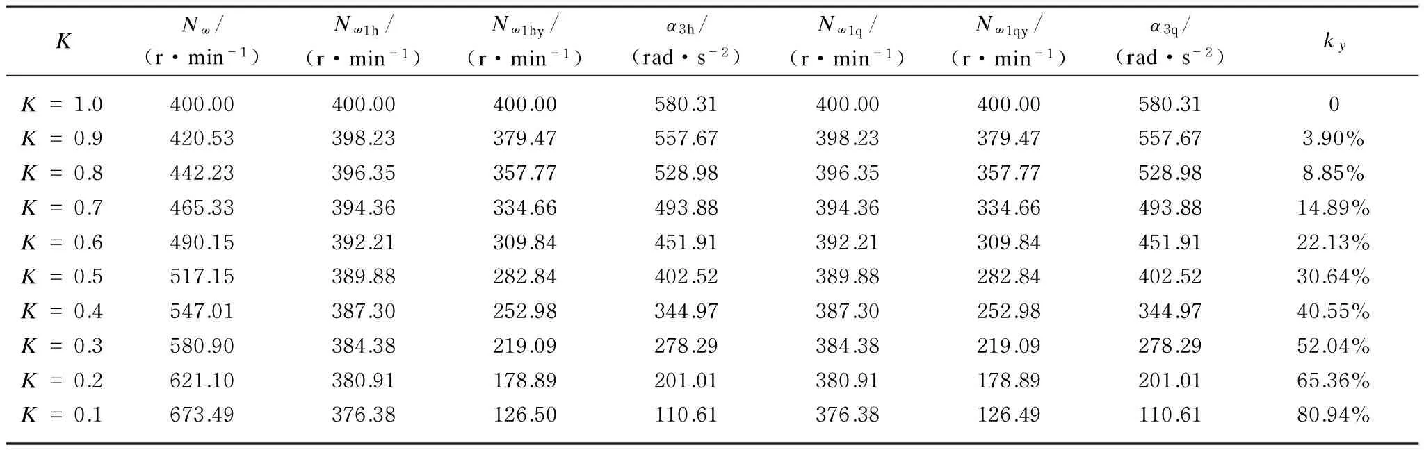
All the parameters of Fig.3 are listed in Table 1.Kis the optimal coefficient;Nωis the velocity of the cotton comber;Nω1his the actual velocity of the nipper balance shaft on the last location;Nω1hyis the theoretical velocity of the nipper balance shaft on the last location;α3his the actual angular acceleration of the nipper balance shaft on the last location;Nω1qis the actual velocity of the nipper balance shaft on the first location;Nω1qyis the theoretical velocity of the nipper balance shaft on the first location;α3qis the actual angular acceleration of the nipper balance shaft on the first location; andkyis the optimal angular acceleration coefficient of the nipper balance shaft on the first and last locations, as follows:
(24)
Each indicator of the cotton comber was synthesized. Optimal coefficientkwas equal to 0.6 andkywas equal to 22.13%. That is, the angular acceleration for the first and last locations was decreased by 22.13% compared with the uniform velocity. The movement relation between the angular displacementθ1yof the input shaft and the angular displacement of the nipper balance shaftω1ywas shown in Fig.4.
Table 1 Optimal coefficientKand the optimization ratio of the angular acceleration of the nipper balance shaft
KNω/(r·min-1)Nω1h/(r·min-1)Nω1hy/(r·min-1)α3h/(rad·s-2)Nω1q/(r·min-1)Nω1qy/(r·min-1)α3q/(rad·s-2)kyK=1.0400.00400.00400.00580.31400.00400.00580.310K=0.9420.53398.23379.47557.67398.23379.47557.673.90%K=0.8442.23396.35357.77528.98396.35357.77528.988.85%K=0.7465.33394.36334.66493.88394.36334.66493.8814.89%K=0.6490.15392.21309.84451.91392.21309.84451.9122.13%K=0.5517.15389.88282.84402.52389.88282.84402.5230.64%K=0.4547.01387.30252.98344.97387.30252.98344.9740.55%K=0.3580.90384.38219.09278.29384.38219.09278.2952.04%K=0.2621.10380.91178.89201.01380.91178.89201.0165.36%K=0.1673.49376.38126.50110.61376.38126.49110.6180.94%
2.2 Vibration and noise test
The cotton comber generates vibrations because the alternating motion of the nipper balance shaft mechanism acquires an incentive function and transfers from the bearing to the wall. This process not only affects the stability of the system, but also limits comber quality. The alternating motion of the nipper balance shaft mechanism resulting in vibration limits the improvement of comber velocity. In order to analyze the effect of comber vibration to the velocity, vibration severity was tested based on the velocity of the nipper balance shaft and the optimal coefficientkwas changed under similar conditions. Six testing points were set from the cotton comber. Three directions of the effective vibration velocity (mm/s) were measured at each testing point:X-(vertical);Y-(horizontal direction);Z-(longitudinal direction). The arrangement of the vibration test points is shown in Fig.5. The data presented in Table 2 showed the respective noise measurements after the comber was operated for two hours.
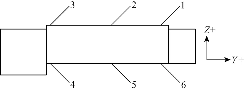
Fig.5 Arrangement of the vibration test points of the cotton comber
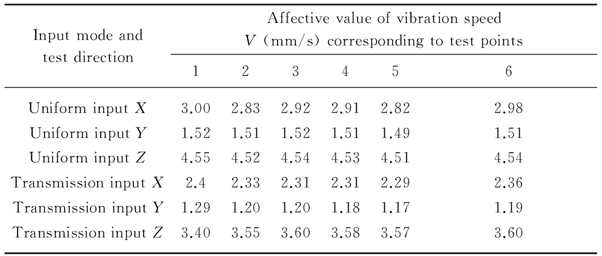
Table 2 Vibration testing data of the nipper balance shaft
Substituting the original testing data in Table 2 into Eq. (25), the vibration severityVywas obtained as 5.59 mm/s when the velocity of nipper balance shaft was a constant and the vibration severityVbwas obtained as 4.42 mm/s when the velocity of nipper balance shaft was variable. Comparing the vibration severitiesVyandVbon the uniform or variable input, the result was obtained that the nipper balance shaft mechanism adopting variable input could increase the vibration obviously. The testing data validated that the nipper balance shaft adopting a servo transmission input could reduce the vibration of comber.
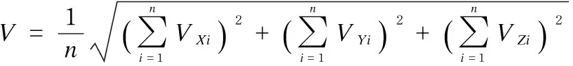
(25)
3 Conclusions
The alternate motion of comber nipper balance shaft causes vibration, which limits comber velocity. This study adopts a servo motor to drive nipper balance shaft mechanism. The following conclusions are summarized from the preceding analysis and calculations.
(1) The nipper balance shaft of cotton comber adopts a transmission input drive to efficiently control the movement of nipper balance shaft, particularly the angular velocity and the acceleration of each location point.
(2) The vibration and noise of the comber have been reduced efficiently by adjusting the angular acceleration of the vibration stimulation point of the nipper balance shaft.
(3) This study proves that using transmission input to improve the dynamic characteristics and mechanical properties of the proposed method is feasible and effective.
Limited by the test conditions,this study only tests the vibration noise to indirectly reflect vibration. Testing each vibration in one movement cycle of cotton comber nipper balance shaft will be more convincing for the research and the analysis of transmission input.
[1] Li X R, Jiang X M, Yang J C,etal. Study on Flock Detaching Motion of a Cotton Comber [J].JournaloftheTextileInstitute, 2014, 105(8): 789-793.
[2] Ren J Z, Yu C W. Analyze the Kinematical Characteristics of Driving Mechanisms of Nipper on E7/6 Type Comber [J].JournalofTextileResearch, 2004, 25(3): 33-34.
[3] E80 Comber for Productivity, Quality & Economy[J].IndianTextileJournal, 2012, 122(12): 95.
[4] Kulkarni S G, Pramod R B, Niyin V K,etal. Optimization of Comber Draft [J].IndianTextileJournal, 2007, 117(10): 30-32.
[5] Ren J Z, Yu C W. Influence of Crack Radius of E7/6 Type Comber on Its Process Performance [J].JournalofTextileResearch, 2004, 25(4): 45-46.
[6] Yan H S, Soong R C. Kinematic and Dynamic Design of Four-Bar Linkages by Links Counterweighing with Variable Input Speed [J].MechanismandMachineTheory, 2001, 36(9): 1051-1071.
[7] Yan H S, Soong R C. Kinematic and Dynamic Design of Four-Bar Linkages by Mass Redistribution with Variable Input Speed [J].JournaloftheChineseSocietyofMechanicalEngineers, 2002, 23(4): 321-332.
[8] Yan H S, Chen W R. Optimized Kinematic Properties for Stevenson-type Presses with Variable Input Speed Approach [J].JournalofMechanicalDesign,TransactionsoftheASME, 2002, 124(2): 350-354.
[9] Yan H S, Soong R C. Kinematic and Dynamic Design of Four-Bar Linkages with Variable Input Speed and External Applied Loads [J].TransactionsoftheCanadianSocietyforMechanicalEngineering, 2002, 26(3): 218-310.
[10] Yan H S, Yeh C C. Integrated Kinematic and Dynamic Designs for Variable-Speed Plate Cam Mechanisms[J].ProceedingsoftheInstitutionofMechanicalEngineersPartC-JournalofMechanicalEngineersScience, 2011, 225(C1): 194-203.
[11] Ou F M, Yan H S, Tang M F. The Synthesis of Mechanism Systems Using a Mechanism Concept Library [J].TransactionsoftheCanadianSocietyforMechanicalEngineering, 2010, 34(1): 151-163.
[12] Hua D N, Tang Z W. Mechanism Analysis and Design [M]. Beijing: China Textile & Apparel Press, 1985: 10. (in Chinese)
[13] Zhang K, Leen A, Wang C B. Computer Graphics Principles[M]. Beijing: China Machine Press, 2012: 61. (in Chinese)
Foundation items:National Basic Research Program of China (973 Program) (No. 2010CB334711); Textile Vision Science & Education Fund, China (No.2012); National Natural Science Foundation of China (No. 51205288)
TS112.2 Document code: A
1672-5220(2015)01-0053-05
Received date: 2014-01-14
* Correspondence should be addressed to LI Xin-rong, E-mail: lixinrong7507@hotmail.com
杂志排行

Journal of Donghua University(English Edition)的其它文章
- Joint Optimization Strategy for Video Transmission over Distributed Cognitive Radio Networks
- Asymptotic Behavior of the Drift Coefficient Estimator of Stochastic Differential Equations Driven by Small Noises
- Adaptive Modulation and Coding Based on Fuzzy Logic Cognitive Engine
- Modeling and Simulation of P-Aloha, CSMA/CA and MACAW Protocols for Underwater Acoustic Channel
- Design and Analysis of Axial Thrust Roller-Exciting Vibrating Table and Its Motor-Control System Based on Co-simulation
- Effects of Compression Garments on Lower Limb Muscle Activation via Electromyography Analysis during Running