Design of a titl angle measurement system based on ADXL345 sensor
2014-09-07SUYanpingGONGMaofaANBinZHANGJianyuZHAOXujie
SU Yan-ping,GONG Mao-fa,AN Bin,ZHANG Jian-yu,ZHAO Xu-jie
(College of Electrical Engineering and Automation,Shandong University of Science and Technology,Qingdao 266590,China)
With the great need of inclination angle measurement technology in the fields of fishery,navigation,robotics,medicine,mine,aerospace,machinery and manufacturing,there are many deficiencies in some aspects about the current inclinometer sensor performance. According to the working principle,the traditional tilt sensors can be classified into three kinds of solid pendulum angle sensor,liquid pendulum angle sensor and gas pendulum angle sensor. To some degrees,there are some disadvantages about the three kinds of sensors. The process is complicated for the solid pendulum angle sensor. What is more,the resistance to the strong shock and vibration is weak. As for the liquid pendulum angle sensor,there is the narrow range of motion and the low frequency of dynamic response. The motion control of the gas pendulum angle sensor is more complex,which is difficult to achieve the required accuracy[1]. However,the acceleration sensor based on micro-electromechanical systems (MEMS) technology is miniaturized,multi-functional,intelligent sensor of small size,low power consumption,high sensitivity and light weight. And the acceleration sensor is convenient to install and debug. According to the above analysis,the system uses intelligent sensor ADXL345 as the measuring sensor of simple structure,low cost and high precision for the angle measuring instrument. In addition,this angle measuring instrument can be widely used in engineering practice.
1 Measuring principle
When the sensor ADXL345 is powered,the differential capacitance unbalances and the inertial mass deflects inside the acceleration sensors[2]. Output voltage value of the sensor is proportional to value of the acceleration. At this moment,the voltage is converted by the integrated AD converter in the sensor and filtered. Under control of the interrupt logic unit,the processed voltage value is stored in the FIFO memory. Finally,the digit signal is transmitted to the external controller through the serial interface.
The inclination angle cannot be measured directly in the system. The angle value is obtained according to three-axis (X,YandZ) acceleration sensor ADXL345. The acceleration is measured in the stationary state. According to components of the gravitational acceleration in the three-axis,angles between the gravitational acceleration and each axis can be calculated[3]. The angle is the measured inclination. Relationship between three-axis component of the gravitational acceleration and tilt angle is shown in Fig.1.
Inclination angle formula can be got from Fig.1. The formulas are shown as below.
(1)

(2)

(3)
whereAX,AY,AZare gravitational acceleration components of each axis.

Fig.1 Relationship between three-axis component of the gravitational acceleration and tilt angle
According to Eqs.(1)-(3),three tilt angles can be obtained. The three tilt angles are the angles of the measured objects. Relative to the previous single-axis and double-axis acceleration sensor,the three-axis acceleration sensor can not only increase in sensitivity but also expand in the measurement range.
2 Design of hardware
Hardware structure of the system mainly contains modules of the tilt angle measured,the MCU control,LCD display and stabilized power supply. The sensor module and the microcontroller are connected via IIC communication. The system block diagram is shown in Fig.2.

Fig.2 The block diagram of system
2.1 Tilt angle measurement module
The sensor ADXL345 is a small and thin accelerometer which is adopted by the system. The current value of the sensor is only 0.1 μA in standby mode of low consumption[4]. The measuring instrument sensor is placed in standby mode to reduce power consumption when the work is not required[5]. The resolution which the users can select is 10-bit fixed resolution and full resolution. The sensor with 13-bit resolution used in this system is able to measure the inclination angle change which is less than 1.0°. In addition,the 32-level FIFO buffer which is integrated in the sensor stores the data. So the load on the host processor and the power consumption of the system are reduced[6].
ADXL345 communicates with the microcontroller by IIC bus. IIC bus which consists of the data line SDA and the clock line SCL is used to send and receive the data[7]. In addition,the pull-up resistor is needed in each of the data line SDA and the clock line SCL. IIC bus is placed in the MSP430 microcontroller port for communication between the sensor and the microcontroller. Fig.3 shows the communication between the sensor and the microcontroller. As seen in Fig.3,the clock line SCL is configured at P5.0,and the data line SDA is configured at P5.1.

Fig.3 Diagram of IIC communication circuit between sensor and microcontroller
2.2 Microcontroller control module
The MSP430F149 microcontroller which is selected by the MCU control module is the core of the data processing and signal control. The data acquisition,angle computing and LCD display control can be completed by the MSP430F149 microcontroller,which owns special functions only existing in DSP,such as 16 multi-functional hardware multiplier,hardware multiply-add function,DMA. The above advanced structural system greatly increases its data processing speed and computing capacity[8]. The advanced JTAG debug is supported by the MSP430 microcontroller. The hardware simulation tool is easy to be promoted because it is a very simple parallel port converter,and the integrated software environment which is provided by IAR can be better used.
2.3 LCD display module
LCD1602 is used to display the tilt angle value. Its working voltage is from 4.5 V to 5.5 V,and its capacity is 162 characters with working current of 2 mA when the backlight is not open. LCD1602 has lots of advantages,such as high sufficiency,easy development and low cost[9]. It has a total of 16 ports,which include positive and negative backlight,positive and negative power supply,LCD bias signal,eight I/O ports and three command options. Eight I/O ports and three selection terminals of the command are configured to the MSP430 microcontroller. P3.0 is set to data or command options. P3.2 is set to choose for reading and writing. P3.3 enable terminal. It is worth noting that the MSP430F149 is without LCD driver. So the driver chip is added between MCU and LCD while 74HC595 is adopted as the drive chip for the system.
2.4 Stabilized voltage supply module
The WRA_P-3W&WRB_P-3W Series are specially designed for application where wide range input voltage power supplies are isolated from the input power supply in a distributed power supply system on a circuit board. These products are widely used in regulation of the output voltage and demand of the output ripple noise. CYT78L05 offers an effective output impedance improvement of two orders of magnitude,and the lower quiescent current[10]. The fixed voltage regulator provides local or on-card regulation for elimination of noise and distribution problems associated with single point regulation.
The merits of power regulation characteristics will directly affect the sensor accuracy in this measurement system. According to requirements of the system and characteristics of WRA1212 and 78L05,the system uses WRA1212 DC/DC isolated module,which can supply ±12 V DC voltage for the system. The input and output of the modules meet requirements of the isolation. The design also effectively prevents the external noise coupling interference. Furthermore,78L05 and TPS76033 linear voltage regulator system can respectively provide DC voltages of 5 V and 3.3 V for the system. Stabilized voltage supply circuit diagram is shown in Fig.4.

Fig.4 Diagram of stabilized voltage supply circuit
3 Design of software
The design of software mainly includes system initialization,the communication between the senor ADXL345 and MCU,LCD1602 display and communication between LCD1602 and MCU. Fig.5 shows flow diagram of design of the software.
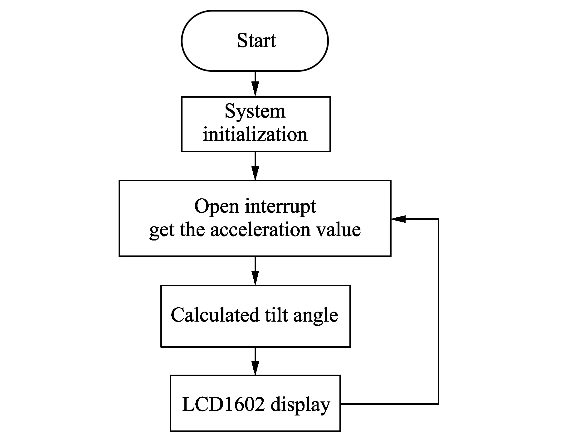
Fig.5 The flow diagram of design of the software
System initialization includes initialization of the system clock,port initialization,ADXL345 initialization and IIC initialization. Port initialization includes IIC communication port initialization and LCD display port initialization. Initializations of the acceleration sensor ADXL345 are as follows. Firstly,a self-test function is disabled. Secondly,an interrupt is generated when the low level arrives. And the 13-bit full-resolution is set up. Finally,the output data is right-aligned and range of ±2 g is set up.
After the system is powered and the ADXL345 is initialized,the number of interrupt samples is set. The watermark interrupt is set when the number of samples is equal to the number of interrupt samples. Once the interrupt signal is set,corresponding part of the sensor reads the three-axis (X,YandZ) acceleration from FIFO memory,and the value of the acceleration is stored in the array[11]. Then,the tilt angle of each direction is calculated through the calculating formulae of tilt angle. To ensure the stability of the data,the average of multiple angle values should be obtained. Finally,value of the tilt angle is displayed on the display screen of LCD1602.
4 Experimental results
This design can achieve digital angle measurement by using MSP430F149 and ADXL345. The experimental results show that response frequency of the inclinometer is very high. The measurement accuracy can achieve ±3° which has met the engineering requirements of tilt angle measurement. Table 1 shows the experimental data as below.
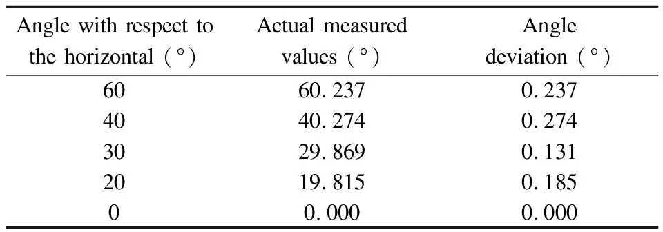
Table 1 Tilt angle measurement data of experiment
5 Conclusion
New digital angle measuring instrument has many advantages,such as simple hardware structure,good software portability and convenient expansion of peripheral circuit. Therefore,the instrument will be widely used for the testing instrument.
[1] SHEN Jian-hua,YANG Yan-qin. Principles and applications of 16-bit ultra power microcontroller based on msp430 series. Beijing: Tsinghua University Press,2004.
[2] ZHOU Qing-fei,XU Ming-long. Design and implement of high-resolution inclination measuring system based on MSP430. Automation & Instrumentation,2011,(1): 40-42,48.
[3] XU Xiao-xiang,CHEN Wen-xiang,YE Jun-jun. Design of angle measurement system based on three-axis acceleration sensor. Sensor World,2012,(7): 32-36.
[4] DUAN Xiao-ming,LI Jie,LIU Wen-yi. Design of digital dipmeter based on MEMs accelerometer. Electronic Design Engineering,2009,17(8): 71-72.
[5] JIANG Hai-tao,GUO Zhan-ying. Design of aircraft tilt measurement system based on mesm accelerometer sensor. Computer Measurement & Control,2010,18(1): 107-109.
[6] ZHANG Wei. Developing a portable digital inclinometer based on MSP430 MCU. Industrial Instrumentation & Automation,2006,(2): 70-72.
[7] LI Shi-zhao. The design and implementation of 2-axis inclinometer based on AVR microcontroller. Jilin: Jilin University,2009.
[8] TIAN Xiao-fang,LU Qi-yong,XIONG Chao. Design of tilt-sensor based on accelerometer. Chinese Journal of Sensors and Actuators,2006,19(2): 361-363.
[9] LING Xiao-bo,CUI Yong-jun,ZHEN Guo-yong,et al. Digital display obliquity measuring instrument based on accelerometer. Transducer and Microsystem Technologies,2008,27(1): 64-66.
[10] LI Bin,WANG Chaoyang,BO Tao,et al. The mini system design based on MSP430F149. Foreign Electronic Measurement Technology,2009,28(12): 74-76.
[11] SUN Xue-fei. Data acquisition system research and design based on MSP430. Changsha: Central South University,2013.
杂志排行

Journal of Measurement Science and Instrumentation的其它文章
- Application of Kalman filter on mobile robot self-localization
- Status and development trend of asphalt foaming process
- Research and simulation of two-level grid-connected photovoltaic inverter system
- Research on temperature control module of injection molding machine based on C8051F020
- Design and application of integrated automation system platform of mine based on PON
- A method of elimination of undesired resonant points of microstrip antenna by cutting U-shaped slot on the ground