Influence of salt fog test on the performance of the composite coating on avionics cases
2014-09-06ChengyuJUXiaohuiWANGRunZHUXiaomingREN
Cheng-yu JU , Xiao-hui WANG, Run ZHU, Xiao-ming REN
Reliability and Systems Engineering, Beihang University, Beijing 100191, China
Influence of salt fog test on the performance of the composite coating on avionics cases
Cheng-yu JU†, Xiao-hui WANG, Run ZHU, Xiao-ming REN
Reliability and Systems Engineering, Beihang University, Beijing 100191, China
Abstract:Aircraft materials and products can be corroded by the salt fog environment in ocean areas. In this paper, the performance of the composite coating on the avionics cases was examined by salt fog test. Coating’s failure mechanisms were analyzed according to the electrochemical method and infrared analysis. The result shows that physical factor is the main reason for the coating failure. The micro-holes and defects are the sources that pitting corrosion occurs on the metal. What is more, integrity is affected by the micro defect. The main reason for the coating failure is that those electrolytes penetrate into the coating through micro-holes and defects, finally reach to the metal substrate and cause corrosion on the metal. The whole corrosion process can be characterized accurately by EIS (Electrochemical Impedance Spectroscopy).
Key words:Composite coating, Salt fog test, Electrochemical impedance spectroscopy
1.Introduction
Metal/coating system is widely used to protect substrate material from corroding and improve service life by the aircraft and other weapons and equipment[1-2],the contribution of the coating includes shielding effect,resistance effect, cathodic protection, and so on[3-4]. These effects mainly depend on the film-forming materials of the coating and inhibiting pigment. The coating on the avionics cases can be corroded by the salt fog environment in ocean areas over time. At last the coating ages and then falls off[5]. What’s more, lots of heat is generated by the computer inside the avionics cases, it leads to the coating in a high temperature environment. The corrosion and damage of the coating is largely accelerated by the salt fog and the high temperature. Metal/coating system during the process of failures always accompanies a series of electrochemical changes[6-7]. The information about metal corrosion and protective properties of organic coatings can be available through detecting changes of electrochemical signals[8-12]. In this paper, the properties of composite coating in high temperature and salt fog environment were studied through the Electrochemical Impedance Spectroscopy (EIS), Infrared Spectroscopy (IR) and Scanning Electron Microscopy (SEM).
2.Test methods and test scheme
2.1.Test material
The metal substrates of sample were 2A12 aluminum which is widely used as the aircraft materials, the topcoat material of the composite coating waspolyurethane enamel, and the prime material was yellow zine acrylic polyurethane varnish.
2.2.Test conditions
The composite coating on the avionics cases is protected from ultraviolet radiation inside the aircraft, but it works in the coastal areas and can be destroyed by the salt fog and high temperature. So the salt fog test was scheduled to examine the performance of the coating.
NQ-1000A® salt spray cabinet was used in the laboratory test. Test conditions, according to MIL-STD-810[13], were as follows: the NaCl concentration was 5% with a PH value of ~ 6.5~7.2, the temperature was 50℃±1℃, and the fall out rate was 1.5 mL/80(cm2·h).
2.3.Measurement of EIS
Potentiostat/Galvanos-tat Model 263A® potentiostatic instrument and PAR M5210® lock-in amplifier were used for the information of the EIS in the laboratory test. Sample area tested by the EIS was 0.785 cm2, test solution was 5% NaCl solution, the traditional three-electrode system was performed, reference electrodes were calomel electrode, and auxiliary ones were platinum electrode. The spectrum was obtained with zero DC offset using frequency range of 10-2~105Hz and AC amplitude of 20 mV.
3.Results and discussion
3.1.EIS and modeling
Results of the EIS measurements in the form of bode and nyquist plots are shown in Figure 1 and Figure 2. Z indicates the electrochemical impedance, and F indicates the frequency. From these Figures 1~2, it can be seen that the value of the low frequency impedance is very high and almost reach to 1 010 Ω·cm2, it means the coating is similar to a pure capacitor, fewer defects of the coating exist before the salt fog test. The coating can protect the metal substrate against corrosion because that the salt ions can be blocked.The EIS spectra from attached films were analyzed using nonlinear least squares fitting (with ZSimWin) to anR[QR] model circuit as illustrated in Figure 3.Rsindicates solution resistance.QcandRcindicate coating capacitor and its resistor. The value of coating capacitor and its resistor are 6.461×10⁻¹⁰F and 1.1×10¹⁰Ω respectively according to the analysis on equivalent circuit.
The water molecules penetrate through the pore of coatings and finally reach to the metal interface as the time goes. Electric double layer capacitor which was connected in parallel with the interfacial resistance would be produced on the corrosion interface, and then causes the corrosion reaction. Because the corrosion process took place in the bottom of coatings, there are series systems between the hole resistance and the interfacial reaction of resistance.
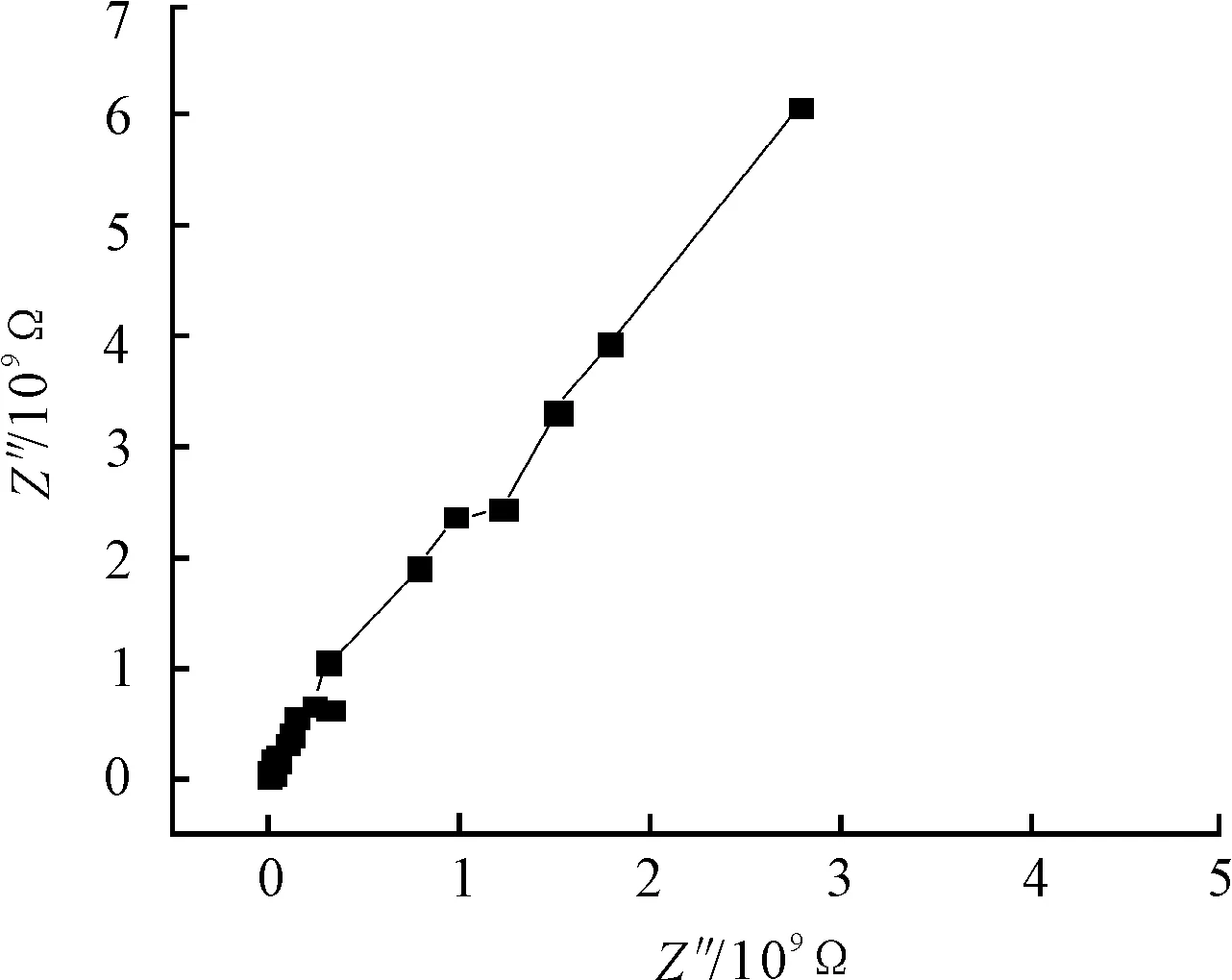
Figure 1.Nyquist plot for coating before the salt fog test

Figure 2.Bode plot for coating before the salt fog test

Figure 3.Model circuit for coating before the salt fog test
There are few holes and defects in the bottom to be penetrated by the water molecules at the early reaction period. The barrier is still existence for the coating. The coating capacitance (Qc) and pore resistance (Qc//Rt) compose parallel system.
Results of the EIS measurements in the form of nyquist plots andR[Q[R[QR]]] model circuit after 345 hours exposure are shown in Figure 4 and Figure 5. The value of coating resistor is 1.65×10⁹Ω according to analysis on equivalent circuit.
Soon afterwards, weber impedance is emerged after long time corrosion (Figure 6). According to the result of SEM, it can be judged that the existent of the pigment of zinc chrome yellow indicates that it is first corroded to protect the metallic substrate. The product after chemical reaction attaches to the potential corrosion activity points and covers it. It is the reason of the emergence of weber impedance. The EIS spectra are analyzed using nonlinear least squares fitting (with ZSimWin) to anR[Q[R[Q[RW]]]] model circuit as illustrated in Figure 7.Zwindicates the weber impedance, and coating capacitor is taken place of phase components (Q) generally in this picture. Phase components (Q) is defined as follow:
Z(jω)=(Y0)-1(jω)-n
Y0indicates the constant,jindicates the imaginary unit, andωindicates the angular frequency. Obviously, phase components (Q) is ideal capacitors whenn=1.
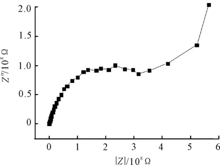
Figure 4.Nyquist plot for coating after 345 h exposure
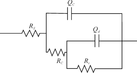
Figure 5.Model circuit for coating after 345 h exposure

Figure 6.Bode plot for coating after 533 h exposure
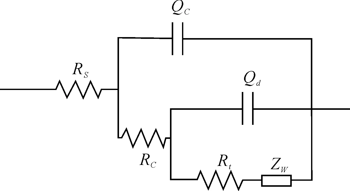
Figure 7.Model circuit for coating after 533 h exposure
3.2.The analysis of the infrared spectrum
Infrared spectrum of the coating after the different exposure time is shown in Figure 8. Different functional groups can be analyzed. 2 850~2 920 cm-1is CH2-dissymmetric stretching, The indicative peak of C=O stretching vibration appears at 1 728 cm-1and 1 688 cm-1, The peak near 1 515 cm-1is C-N- stretching vibration from polyurethane. The peak of CH2- symmetrical bending and CH3- unsymmetrical bending appears at 1 450 cm-1.
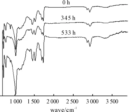
Figure 8.Infrared spectrum after different exposure time
It can be found that peak positions and peak height do not change according to the result of infrared spectroscopy (IR). It means that the elemental composition of the coating does not change during the experiment. So, physical factor is the main reason for the coating damage rather than chemical factor.
3.3.Morphology by scanning electron microscope
The change of coating morphology is shown in Figure 9 and Figure 10. It can be seen that the adhesive is gradually eroded away after the salt fog test.
Only hard particles phase is left, there are some small holes and other defects on the surface of the coating. It is the source that pitting corrosion occurs on the metal. What is more, the integrity is affected by the micro defect. The main reason for the coating failure is that the electrolyte penetrates into the coating through micro-holes and defects, finally reaches to the metal substrate and causes corrosion on the metal. The corrosion products which are generated by the chemical reaction block the micro-holes and defects and reduce the permeability of oxygen.
As presented in Figure 11, cathode and anode region are separated because the higher oxygen permeates in other parts. There is a lower PH value in the anode region, but higher PH value in the cathode region. Corrosion products are generated as the diffusion of the anions and cationic. Blister or peeling happens with the increase of the corrosion products. It expands the contact area between the metal substrate with liquid electrolyte. This will result in the worse corrosion generally.
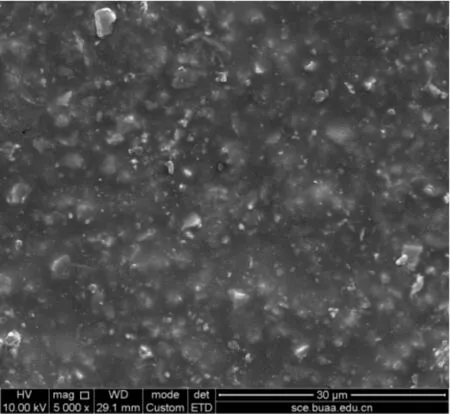
Figure 9.Coating morphology before the salt fog test

Figure 10.Coating morphology after 345 h exposure
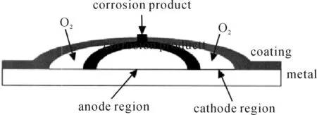
Figure 11.Schematic diagram of electrochemical corrosion
4.Conclusion
1) The degradation process of the coating can be accurately characterized by EIS which not only characterizes the corrosion mechanism according to the process of corrosion but also quantitatively studies the degradation process of resistor and capacitor. There will be a better result with the help of EIS and IR. The salt fogs play a very important effect on coating failures.
2) The content and types of the functional groups have not changed according to the IR after the salt fog test. The most likely reason is that the salt fogs have a strong corrosive. After a long period, the coating is eroded. The water molecules reach to the metallic substrate by micro-holes and defects. At last the metal substrate is corroded quickly, and then bubble and crack also happen.
References
[1]Zhou C, Lu X, Xin Z, et al. Hydrophobic benzoxazine-cured epoxy coatings for corrosion protection[J]. Progress in Organic Coatings, 2013,76(9):1178-1183.
[2]Song Enpeng, Liu Wenting, Yang Xu. Study on accelerated corrosion test environment spectrum for internal aircraft structure[J]. Acta Aeronautica et Astronautica Sinica, 2006, 27(4):643-649.
[3]Ranjbar, Z, Moradian S, Attar M R M Z. EIS investigation of cataphoretically electrodeposited epoxy coatings having different EEWs[J].Progress in organic coatings, 2004,51(2):87-90.
[4]Le Pen C, Lacabanne C, Pébère N. Characterisation of water-based coatings by electrochemical impedance spectroscopy[J]. Progress in organic coatings, 2003,46(2):77-83.
[5]Luo Zhenhua, Yao Pei, Cai Jianping, et al. Progress ofevaluation techniques for organic coatings performance[J]. Corrosion Science and Protection Technology, 2004,16(5):314-317.
[6]Hinderliter B R, Croll S G, Tallman D E, et al. Interpretation of EIS data from accelerated exposure of coated metals based on modeling of coating physical properties[J].Elctrochimica Acta, 2006, 51(21): 4505-4515.
[7]Zhang Jintao, Hu Jiming, Zhang Jianqing, et al. A review on modern method of organic coatings[J]. Journal of Materials Science and Engineering, 2003,21(5): 763-768.
[8]Darowicki K, Slepski P, Szocinski M. Application of the dynamic EIS to investigation of transport within organic coatings[J]. Progress in Organic Coatings, 2005, 52(4):306-310.
[9]Bierwagen G, Tallman D, He J P, et al. EIS studies of coated metals in accelerated exposure[J]. Progress in Organic Coatings, 2003, 46(2): 148-157.
[10]Sharer Z, Sykes J. Insights into protection mechanisms of organic coatings from thermal testing with EIS[J]. Progress in Organic Coatings, 2012,74(2):405-409.
[11]Fredj N, Cohendoz S, Feaugas X, er al. Ageing of marine coating in natural and artificial seawater under mechanical stresses[J]. Progress in Organic Coatings, 2012,74(2):391-399.
[12]ZHANG W, WANG J, LI Y N, et al. Evaluation of metal corrosion under defective coatings by WBE and EIS technique[J]. Acta Physico-Chimica Sinica, 2010,26(11):2941-2950.
[13]Zuo S, Yao C, Liu W, et al. Porous palygorskite-polythiophene conductive composites for acrylic coatings[J]. Journal of Applied Polymer Science,2013,129(5):2707-2715.
[14]MIL-STD-810 Committee. Environmental Test Methods and Engineering Guides[S]. MIL-STD-810F, 2000.
(Continued from 53 page)
DOI:10.3969/j.issn.1001-3881.2014.06.006
Received: 2013-11-16
† Cheng-yu JU, E-mail:juchengyu@139.com
杂志排行

机床与液压的其它文章
- Control of EPS with regulating factor
- Numerical simulation of the double suction balance type screw compressor working process*
- Cam profile optimization design of variable cycle reciprocating piston engine*
- Design and implementation of a wireless electronic inverter welding machine*
- A Sort of fusion control strategy for uncertainty complex process with large time lag*
- Flow field CFD analysis of axial flow blood pump*