16-QAM调制的双偏振100-Gb/s码分复用-正交频分复用信号的产生和传输
2014-08-16郭昌建戴龙玲黄凌晨刘柳
郭昌建,戴龙玲,黄凌晨,刘柳*
(1.华南师范大学光及电磁波研究中心,广州510006;2.浙江大学中瑞联合光子研究中心,光及电磁波研究中心,杭州310058)
1 Introduction
As the demand for bandwidth continues to grow,short reach optical fiber systems operating at100 Gb/s will be required to increase the channel capacity.Optical orthogonal frequency division multiplexing(OFDM)[1]has attracted lots of interest due to its high spectral efficiency and robustness towards inter-symbol interference(ISI)caused by chromatic dispersion(CD)and polarization mode dispersion(PMD)[2-3].Experimental demonstrations have been reported for 100-Gb/s optical OFDM transmission using polarization-division-multiplexed higher order I/Qmodulation,coherent detection and digital signal processing[4-9].However,for short reach applications such as optical access networks and data-center networks,the cost for optical I/Qmodulation and coherent detection might be an issue[9].A more cost-effective solution would be to use intensity modulation with direct detection(IM-DD).
Recently,a multicarrier code-division multiplexing(MC-CDM)over fiber system based on spatial coding and subcarrier multiplexing(SCM)was investigated in our previous works[10-11].The proposed MCCDM over fiber system has the following advantages[11]:Higher power budget due to coding gain,the potential of enhanced physical layer security since each user is assigned with a dedicated code,and flexible network management.Furthermore,the proposed MCCDM over fiber system can be naturally integrated with the OFDM concept by using an inverse fast Fourier transform(IFFT)operation after CDM coding,and using an FFT operation before decoding.The resulted CDM-OFDM over fiber system offers an additional degree of freedom compared with conventional optical OFDM systems,since each data symbol is spread over several subcarriers according to the assigned code in frequency domain.Therefore,the total capacity of the channel can be adjusted dynamically by changing the number of users/codes,without the need for altering the hardware infrastructure.
In this paper,itwas experimentally demonstrated about the generation and detection of a 100-Gb/s CDM-OFDM signal using polarization-division multiplexing(PDM),intensity modulation,optical vestigial sideband(VSB)filtering[12]and pre-amplified direct detection.An arbitrary waveform generator with a sample rate of 25 GS/s is used to generate the real valued CDM-OFDM signals.Polarization-division multiplexing is done by using a pair of polarization beam splitter and a variable optical delay line.Transmission over 24.4 km of standard single mode fiber(SSMF)is also demonstrated.The introduction of optical VSB filtering and its impact on the system performance after 24.4 km SSMF transmission ware numerically investigated.The results show that,without optical VSB filtering,the CDM-OFDM signals have a larger chromatic dispersion tolerance and higher receiver sensitivity than conventional OFDM signals.Furthermore,when fully loaded,the CDM-OFDM signal has a similar BER performance as that of a conventional OFDM signal,both in back-toback configuration and after 24.4 km of SSMF transmission.The BER performance of the optical CDM-OFDM signals versus the number of active users is also investigated.
2 Experimental setup

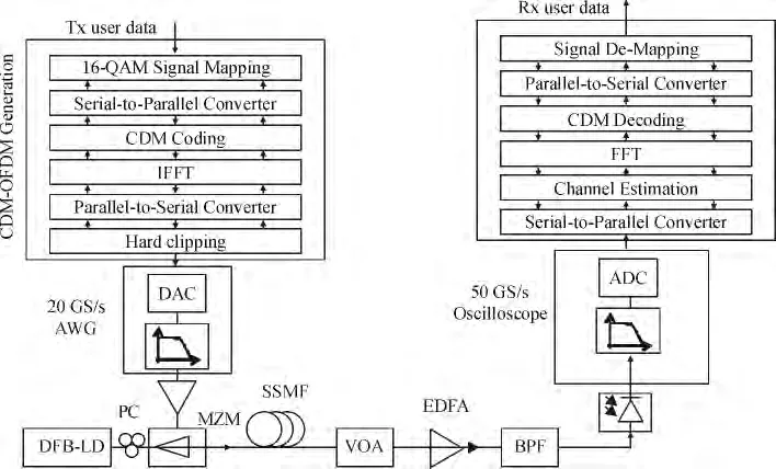
Figure 1 shows the experimental setup of the CDM-OFDM over fiber system.In this experiment,the OFDM signals are generated by an arbitrary waveform generator(Micram AWG-34G).For each of the M users transmitted,16-QAM modulation was used for signal mapping.The modulated complex data symbols xi,i=1,2,…,M,were then spread over N(N=256≥M)subcarriers using Walsh codes.The spectrum spreading(coding)process can be expressed as where x=[x1,x2,…,xM]Tis the vector of data symbols,y=[y1,y2,…,yN]Tis the vector of coded signals,and H is the Walsh code matrix of size N ×M(M≤N).Note that for a code length of N,a set of N Walsh codes can be generated,among which M codes were selected random ly for coding.The coded signal vector y was then placed to the 2nd-257thsubcarriers for a 544-point IFFT operation.The 1st,258th-272ndsubcarriers were zero padded.In order that the OFDM signals after IFFT can be real-valued,the complex conjugates of the 1st-272ndsubcarriers were placed to the 273th-544thsubcarriers,respectively.After IFFT,the signals were parallel-to-serial converted,and then sent to a digital to analog convertor(DAC)with a resolution of6 bits and a sample rate of25 GS/s.The net line rate is94.12 Gb/s.The electrical signals after the DAC were then amplified(SHF 807)and sent to a Mach-Zehnder modulator(Fujitsu FTM7938)for double side-band(DSB)up-conversion.A DFB laser with a centerwavelength of1 549.9 nm were used here as the light source.For each transmitted CDM-OFDM frame,the first symbol was for timing synchronization,the next30 symbols were used as training symbols for channel estimation,and the last 1 000 symbols were effective payloads.It should be noted that since chromatic dispersion only causes frequency selective power fading rather than phase rotation for different frequency components when DSB up-conversion is used,the subcarriers of the received CDM-OFDM signals after photo detection will still remain aligned.Therefore,no Cyclic Prefix(CP)was used in this experiment.Optical VSB filtering was then applied to the modulated signals by using a bandwidth and wavelength tunable optical band pass filter(OBPF).The optical signals were then split into two paths using a polarizing beam splitter(PBS),delayed with respect to each other with an optical delay line placed on one path,and then combined using a polarizing beam combiner(PBC)for polariza-tion-division multiplexing(PDM).Polarization controllers(PC)were used to align X and Y polarization.The PDM optical signals were then sent in 24.4 km of standard single mode fiber(SSMF).At the receiver,a variable optical attenuator(VOA)was used to change the received optical power prior to a pre-amplified receiver which consists of an erbium doped fiber amplifier(EDFA)with a noise figure of about 4.3 dB(Amonics AEDFA-PA-30)and an optical band pass filter(OBPF)with 0.8 nm bandwidth.The optical power of the received signals was measured to be-4 dBm.The pre-amplified optical signals were then polarization demultiplexed using a PC and a PBS and sent to two photo detectors(PD)with a bandwidth of 43 GHz.In practical applications,polarization demultiplexing can be realized by automatic polarization tracking techniques[13].The electrical signals after PD were sampled by a 100 GS/s real time oscilloscope(Tektronix DPO73324D)and processed off-line.The off-line DSP procedures include timing synchronization,channel estimation,serial-to-parallel conversion,FFT,dispreading(decoding),demodulation,and error counting.

Figure 1 Experimental setup
3 Results and discussion
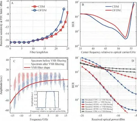
First,the impact of the VSB filtering on the system performance via simulation was investigated.Both single-polarized CDM-OFDM and OFDM signals were considered.For each run,100 symbols of payloads were tested.The results were then averaged over 100 runs.The resolutions for the DAC and ADC were set to 5 and 6 bits,respectively,according to the effective number of bits(ENOB)of current state-of-the-art DAC/ADC devices[14-15].The optical BPF used here was modeled using a 4-th order super-Gaussian filter with a 3-dB bandwidth of 100 GHz.The center frequency of the optical BPF was adjusted so that amini mum BER can be obtained.Other simulation parameters were the same as that used in our experiment.As for the case without VSB filtering,the receiver sensitivity at FEC limit(BER=3.8E-3)as a function of the fiber length was investigated,as shown in Figure 2A.One can see that the CDM-OFDM signals have a better receiver sensitivity that OFDM signals,especially when the fiber length is larger than 15 km.An improvement of about 6 dB can be obtained by using CDM-OFDM signals compared with conventional OFDM signals after being transmitted through 24 km of SSMF.This improvement can also be observed in the simulated as well as the measured curves in Figure 2D.Figure 2B shows the BER as a function of the center frequency of the optical BPF relative to the optical carrier.The received optical power before the pre-amplifier was set to-12 dBm.One can see that for both CDM-OFDM and OFDM signals,the minimum BER can be obtained when the center frequency of the BPF was tuned by 53 GHz away from the carrier frequency.The optical spectra of the signals before and after VSB filtering are shown in Figure 2B.The inset of Figure 2C shows the complete spectrum profile of the BPF.The BER performance of both CDM-OFDM and OFDM signals after 24.4 km of SSMF transmission as a function of the received optical power before the pre-amplifier is shown in Figure 2D.Both measured and simulated curves are given.The center frequency of the BPF used for VSB filtering was set to 57 GHz relative to the optical carrier according to Figure 2B.Conclusions can be drawn from Figure 2A and Figure 2D that:1)when no VSB filtering is used,CDM-OFDM signals have a better BER performance compared with OFDM signals after fiber transmission.This can be partially attributed to the frequency diversity gained by using spectrum spreading;2)By using VSB filtering,significant improvement on the BER performance can be obtained for both CDM-OFDM and OFDM signals,since VSB filtering helps to reduce the frequency selective power fading of the DSB modulated signals induced by chromatic dispersion;3)The BER performance of the CDMOFDM and OFDM signals with optical VSB filtering is roughly the same,except when the received optical power ismore than-10 dBm,where the CDM-OFDM signals exhibits an error floor.The reason for such an error floor may be attributed to the VSB filtering and excessive quantization noise,which causes unorthogonality between CDM users,resulting in additional multiple access interference(MAI).

Figure 2 (A)Simulated receiver sensitivity at FEC limit(BER=3.8E-3)vs.the fiber length.(B)Simulated BER as a function of the center frequency of the VSB filter.(C)Optical spectrum of the CDM-OFDM signals before and after VSB filtering.(D)BER vs.received optical power of CDM-OFDM and OFDM signals before and after VSB filtering
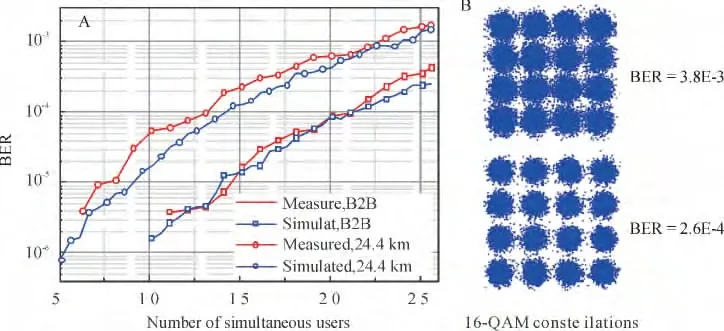
Second,the coding gain of the CDM-OFDM over fiber system with optical VSB filtering was investigated.Figure 3 shows the simulated(blue lines)and measured(red lines)BER and results versus the number of active users.For the experimental results,the received optical power was set to-6 dBm for both back-to-back and 24.4 km transmission cases;as for the simulated results,the received optical power was set to-12 dBm.One can see from Figure 3 that as the number of active users decreases,the BER drops drastically.Therefore,the system capacity can be dynamically arranged by changing the number of active users according to the channel SNR,with out modifying the system architecture.

Figure 3 (A)Simulated(blue lines)and Measured(red lines)BER vs.number of active users in the back-to-back configuration(rectangular dots)and after 24.4 km transmission(circular dots).(B)Constellations of the received 16-QAM CDMOFDM signals after decoding
Finally,the BER performance of the full loaded 100 Gb/s CDM-OFDM signals with optical VSB filtering in both back-to-back and 24.4 km SSMF transmission cases were researched using the experiment setup described above.The performance comparation of the single polarization CDM-OFDM over fiber system with that of the conventional directed detection optical OFDM system is shown in Figure 4A.The parameters used for both systems are the same.The measured optical spectra of the received CDM-OFDM signals after VSB filtering are depicted in the inset Figure 4A.One can see that for both back-to-back and 24.4 km transmission cases,the BER performance with and without CDM coding are roughly the same due to the employment of VSB filtering,with a less than 0.3 dB penalty at FEC limit when CDM coding is used.The measured results have a good agreement with the simulated curves shown in Figure 2D,in that the CDM-OFDM signals have a larger error floor compared with OFDM signals.
The BER results for polarization-division multiplexed(PDM)CDM-OFDM over fiber systems are shown in Figure 4B.It can be seen that in the back-toback configuration,at the FEC limit,the received optical power is-17.4 dBm for single polarization signals(blue circular dotted lines),and-14.3 dBm for dual polarization signals(red circular dotted lines).A power penalty of about3.1 dB is observed.After 24.4 km SSMF transmission,the power penalty of the dual polarization signals(red rectangular dotted lines)at FEC limit are around 3.8 dB,compared with that of single polarization signals(blue rectangular dotted lines).It can also be observed that compared with the BER of back-to-back cases,both single and dual polarization CDM-OFDM signals after 24.4 km SSMF transmission have a penalty of around 4.8 dB at FEC limit.The loss margin for the PDM CDM-OFDM signals after 24.4 km of SSMF transmission is around 5.4 dB,as themaximum optical power obtained in the receiver is-4 dBm.
4 Conclusion
It was investigated and for the first time experimentally demonstrated a CDM-OFDM over fiber system based onmulti-carrier code-division-multiplexing(MCCDM)and direct detection which supports the transmission of 16-QAM modulated,100-Gb/s PDM CDMOFDM signals over 24.4 km of SSMF.It was shown through simulation as well as experiment that without optical VSB filtering,CDM-OFDM signals exhibit a larger chromatic dispersion tolerance than conventional OFDM signals.Therefore,optical CDM-OFDM is a more favorable scheme compared with optical OFDM in short reach applications.When optical VSB filtering is applied,the CDM-OFDM signal has a similar BER performance as that of a conventional OFDM signal,both in back-to-back configuration and after 24.4 km of SSMF transmission.The coding gain of the CDMOFDM signals was also investigated.
[1]Shieh W,Djordjevic I.OFDM for optical communications[M].Pittsburgh:Academic Press,2009.
[2]Lowery A J,Armstrong J.Orthogonal-frequency-division multiplexing for optical dispersion compensation[C]∥Optical fiber communication conference. California,USA,2007.
[3]Coura D JC,Silva JA L,Segatto M E V.A band-width scalable OFDM passive optical network for future access network[J].Photonic Network Communications,2009,18(3):409-416.
[4]Schmidt B J,Zan Z,Du L B,et al.100 Gbit/s transi mssion using single-band direct-detection optical OFDM[C]∥Optical fiber communication conference.California,USA,2009.
[5]Giddings R P,Jin X Q,Hugues-Salas E,et al.Experimental demonstration of a record high 11.25Gb/s realtime optical OFDM transceiver supporting 25 km SMF end-to-end transmission in simple IMDD systems[J].Optics Express,2010,18(6):5541-5555.
[6]Shieh W,Athaudage C.Coherent optical orthogonal frequency division multiplexing[J].Electronics Letters,2006,42(10):587-588.
[7]Jansen SL,Morita I,Schenk TCW,etal.121.9-Gb/s PDM-OFDM transmission with 2-b/s/Hz spectral efficiency over 1 000 km of SSMF[J].Journal of Lightwave Technology,2009,27(3):177-188.
[8]Shieh W,Yang Q,Ma Y.107 Gb/s coherent optical OFDM transmission over 1000-km SSMF fiber using orthogonal band multiplexing[J].Optics Express,2008,16(9):6378-6386.
[9]Karar A S,Cartledge JC.Generation and detection of a 112-Gb/s dual polarization signal using a directly modulated laser and half-cycle 16-QAM Nyquist-subcarrier-modulation[C]∥European conference and exhibition on optical communication.Amsterdam,Netherlands,2012.
[10]Guo C,Luo C,He S.Electrically processed OCDMA system based on spatial coding and subcarrier multiplexing[C]∥Photonics in switching.Monterey,California,USA,2010.
[11]Guo C,Huang L,He S.Demonstration of 1 Gb/s×15-user CDM over WDM-PON using electrical spatial coding and subcarrier multiplexing[J].Photonics Technology Letters,2011,23(14):953-955.
[12]Kim H,Gnauck A H.10Gbit/s177 km transmission over conventional singlemode fiber using a vestigial side-band modulation format[J].Electronics Letters,2001,37(25):1533-1534.
[13]Cai J,Sinkin O V,Davidson CR,et al.40 Gb/s transmission using polarization division multiplexing(PDM)RZ-DBPSK with automatic polarization tracking[C]∥Optical fiber communication conference/National fiber optic engineers conference.San Diego,California,USA,2008.
[14]Greshishchev YM,Pollex D,Wang SC,etal.A 56GS/S 6b DAC in 65nm CMOSwith 256 ×6b memory[C]∥Solid-state circuits conference digest of technical papers(ISSCC).San Francisco,USA,2011.
[15]Ferenci D,Grozing M,Berroth M,etal.A 25 GHz analog demultiplexer with a novel track and hold circuit for a 50 GS/s A/D-conversion system in InPDHBT Technology[C]∥Microwave symposium digest(MTT).Montreal,QC,Canada,2012.
