Optimized design of machine tool spindle structural parameters
2014-07-31SiqiDENGDengyunMAWeigangZHENG
Si-qi DENG, Deng-yun MA, Wei-gang ZHENG
Intelligent Manufacturing and Controlling Research Institute,Wuhan University of Technology,Wuhan 430063,China
Optimized design of machine tool spindle structural parameters
Si-qi DENG, Deng-yun MA, Wei-gang ZHENG†
IntelligentManufacturingandControllingResearchInstitute,WuhanUniversityofTechnology,Wuhan430063,China
Machine tool spindle is the object to be optimized and designed. Combined the optimum design idea and Matlab, the model optimization to machine tool spindle was put into practice with penalty function. Then modal analysis was carried out by ANSYS. The first six lowest orders of the spindle, mode of vibration and critical speed of revolution were analyzed. And the rationality of structure optimum design of the spindle was verified. This research provides references to the structure optimum design of machine tool spindle.
Machine tool spindle, Penalty function method, Optimum design, Modal analysis, Dynamic behaviour
1.Introduction
Machine tool spindle is the executive component of a machine tool, which supports and drives the cutter or workpiece to finish surface shaping motion, deliver motion. It also bears driving force, cutting force and other load factors. The property of machine tool spindle is one of the most important factors affecting the efficiency and life span of machine tool spindle directly[1]. A machine tool spindle with satisfactory performance shall satisfy the certain rigid requirement which is most determinated by the structural parameters and requires necessary design[2]. As the traditional design scheme relies on the intuitive judgment from experience and computational condition is limited, it is hard to obtain the optimize result. With the development of computer application technology, Matlab and ANSYS take very important roles in the field of optimization design, and improve the design efficiency and quality greatly[3].
2.The optimization model of machine tool spindle
For the case of a stepped shaft with angular contact bearing, the optimization design was carried out. The conditions are show as below:
The input power of the machine tool spindle:P=2 kW; spindle speed:n=1 000 r/min; cutting force to the spindle cantilever end:F=25 kN; spindle inner diameter:d=45 mm; permissible deflection cantilever end:y0=0.05 mm,[φ′]=1°/12 m,[θ]=0.002 5°; double bearings span (L) of spindle: 360 mm ≤L≤ 650 mm; length of cantilever end: 90 mm ≤a≤ 170 mm; external diameter(D1): 80 mm ≤D1≤ 160 mm; diameter(D2)of axle between bearings: 70 mm ≤D2≤ 150 mm; material: 40Cr; density:ρ=7 800 kg/m3;
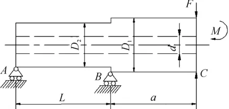
The spindle schematic is shown in Figure 1. By proceeding from the spindle manufacturing cost and the requirement of machining precision, considering the self-weight and the overhanging section of spindle, the model scheme choose the spindle rigidity and periphery limit as the constraint condition, and the minimal mass is the design objective for the model[4].

Figure 1. Sketch map of spindle
2.1.The design variables
When the material of machine tool spindle is designated, the mass of the spindle is a function of the external diameterD1, the diameterD2of axle between bearings, the inner diameterd, the spanLand the lengthaof the extended end. The inner diameter can not be the design variable because it is determined by the machine model, so the design variables show as below:
2.2.The objective function
In the premise of meeting dynamic requirements, reducing the mass, saving the materials, cost reduction, setting the minimum mass as the objective function is commended,ρ—spindle density(kg/m3).
2.3.The designation of constraint functions
1) Rigidity constraints
The deformation of machine tool spindle can affect the processing quality greatly, so the spindle requires satisfactory rigidity and lower deflection of the spindle extended end.
When only considering the acting forceFimpacts on the spindle front end, the displacement of the spindle front end meets this equation:

Whenonlyconsideringthetorqueactingonthefrontendofthespindle,thefrontendofthespindlewillgeneratedisplacementy2:
Here,Mis the torque acted on spindle (N·mm)
The displacement of the front end of the spindleYcan be regarded the sum ofYFin the same plane. So,
In addition,the torqueMacted on machine tool spindle is caused by cutting forceF. To calculate the formula, equationM=2aFwas taken into
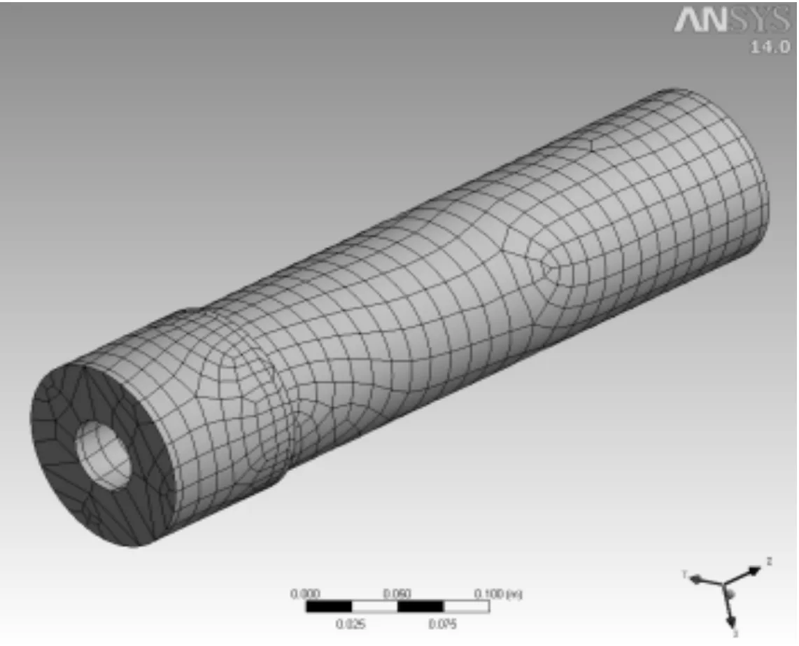
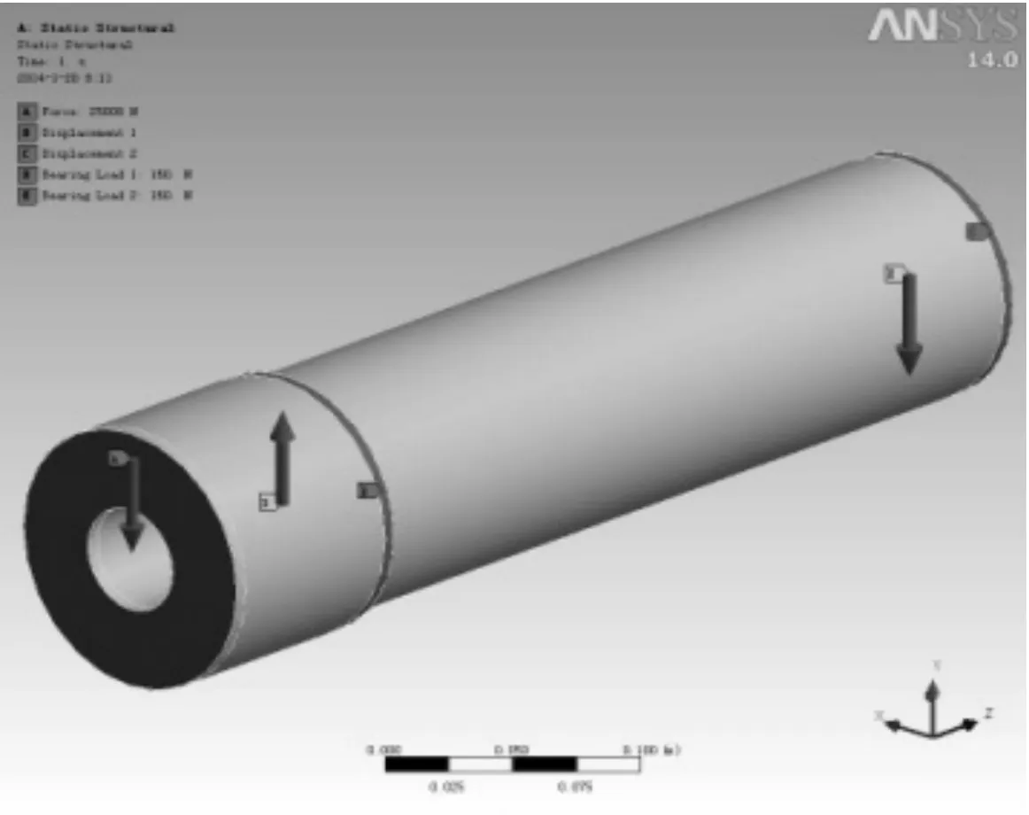
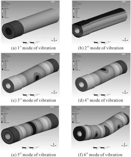
Considering stiffness constraints:y 2) Deflection angle constraints It can be known that the deflection angle onBis the largest after analysis: 3) Torsion deformation limit Shaft torsion rigidity condition could calculate through following formula: 4) Boundary constraints ①Main shaft overhanging section diameter(outer diameter) It can be known from experience that the value range of outer diameterD1is:80≤D1≤160, so ② Axle diameter between bearings The value range of axle diameter between bearingsD2is:70≤D2≤150,so, ③ Bearing span The value range of bearing spanLis:360≤L≤650,so, ④ Length of the cantilever end The value range of the spindle cantilever lengthais :90≤a≤170,so, 2.4.MATLAB realizing Matlab was used to achieve the program. Specific steps are as follows: functionf=jichaungzhuzhou(x) D(1)=x(1);D(2)=x(2);L=x(3);a=x(4);p=7 800;d=45; f=(pi/4)*p*(D(1)^2-d^2)*a+(D(2)^2-d^2)*L; function[c ceq] = jichuangzhuzhouyueshu(x) F=25 000;E=2.1*10^5;P=2 000;G=8.1*10^4;n=16.67;d=45; c(1)=64*F*x(4)^2*((4*x(4)/(x(1)^4-d^4))+3*x(3)/(x(2)^4-d^4))/(3*pi*E)-0.05; c(2)=F*x(3)*x(4)/(3*E*(x(2)^4-d^4))-0.0025; c(3)=180*9549*P/(pi*n*G*pi*(x(2)^4-d^4)/32)-1/12; c(4)=x(1)-80; c(5)=160-x(1); c(6)=x(2)-70; c(7)=150-x(2); c(8)=x(3)-360; c(9)=650-x(3); c(10)=x(4)-90; c(11)=170-x(4); ceq=[]; end x0=[107;102;360;90]; lb=[80;70;360;90]; ub=[160;150;650;170]; A=[]; b=[]; Aeq=[]; beq=[]; [x,fval]=fmincon(@jichuangzhuzhou,x0,[],[],[],[],lb,ub,@jichuangzhuzhouyueshu); Through operating the main program in MATLAB, the following optimized result was obtained,x=[113.357 4 107.634 9 360.000 0 90.000 0] By applying branch-and-bound method, the solving needs 4 branches and 4 cut branches. After 4 times running the linear program, the following optimum result was achieved, X =[114 106 360 90] Fval = 31.1128 3.The dynamic behaviour simulation and analysis of machine tool spindle 3.1.The spindle unit finite element analytical model Considering the machine tool spindle unit is hollow stepped shaft, the scheme ignored the chamfer, circular bead of the spindle surface and other structure details to simplify the model. Moreover, the supports were simplified into elastic supports and the bearing angle rigidity as well as the axial rigidity was ignored. Only the radial rigidity and applying elastic boundary element were considered to simulate the elastic support[5]. Hex Dominant Method was used to divide the meshes which include 11689 nodes and 3568 units. The meshes are as shown in Figure 2. Figure 2. Finite element meshes 3.2.The finite element calculation and analysis of the spindle The calculation and analysis course will add the load and constraints to machine tool spindle. To impend over real environment, a print face was built in DM before the load and constraints impacted, then allowed the load and constraints impact. The constraints include the bearing constraints and the stationary displacement alone z direction. The load is 25 kN. The sketch map of the load and constraints are as shown in Figure 3. Figure 3. Load and constraints The natural frequency of the structure and the mode of vibration are important parameters for the design of supporting dynamic load, the sixth-orders mode of vibration are shown in Figure 4. Figure 4. Six figure mode By carrying out the modal analysis of machine tool spindle and achieving ideal space simulation effect, it is found that the relative displacement of the spindle increased with the number of the orders increased. To avoid the resonance region and guarantee the working accuracy and safety, the maximum rotational speed of machine tool could be over 75% of the 1storder critical speed. According to the relationship of speed and frequencyn= 60f, the 1storder critical speed isn=1 805 r/min. Pre-set working speed of the spindle was 1 000 r /min, which is far lower than the 1storder critical speed. So the spindle unit can avoid the resonance region and it is a reasonable design. Through the example of the optimization for machine tool spindle, this paper illuminates the method of optimization for machine tool spindle structure with outer penalty functions in Matlab. This method achieves the algorithm process of the optimization design primely, facilitates the solving and simplifies the program, which lay a foundation to the modal analysis by referring to determine its vibration characteristics such as inherent frequency and mode of vibration. The result shows that Machine tool spindle structure design is reasonable, and it owns favorable machining precision. Besides, it avoids the resonance region successfully. So this optimization scheme can verify the rationality of structure optimum design of the spindle. It could provide references to the structure optimum design of machine tool spindle. [1] Shi Hongyan.Optimal design of machine tool spindle based on ANSYS[J]. Hunan Agricultural,2013(7):84-85. [2] Liu Hongjuan. Machine tool spindle structure optimization design based on MATLAB[J]. Tool Technology,2012(7):36-38. [3] Feng Haihua,Li Guoping.Machine tool spindle optimization design based on MATLAB[J],2009(2):32-37. [4] Jiang Huiming,Wang Guang.Nc machine tool spindle’s multi-objective optimization[J]. New technologies,2010(7):38-41. [5] Ge Jianbing,Qu Xueqing,Ma Rong.Optimal design of machine tool spindle based on ANSYS[J]. Mechanical engineering and automatic,2011(1):75-79. 2014-03-15 10.3969/j.issn.1001-3881.2014.12.017 † Wei-gang ZHENG, E-mail:zfeidiao@126.com


4.Conclusion
杂志排行
机床与液压的其它文章
- A Simple time-domain method for bearing performance degradation assessment*
- Structural design and performance testing of the electromagnetic proportional pressure relief valve
- Analysis of magnetic field characteristics for different winding cylinder materials of a new type of magnetorheo-logical damper*
- Impacts of centrifuge errors on calibration accuracy of error model coefficients of gyro accelerometer*
- Interior ballistic simulation and parameter influence analysis of an underwater pneumatic launcher*
- Influence of airflow uniformity over the duct outlet of vehicle air-condition on cooling performance*
