Structural design and performance testing of the electromagnetic proportional pressure relief valve
2014-07-31FengxiaHAN
Feng-xia HAN
Mechanical and Electrical Practice Center,Beijing Information Science and Technology University,
Structural design and performance testing of the electromagnetic proportional pressure relief valve
Feng-xia HAN†
MechanicalandElectricalPracticeCenter,BeijingInformationScienceandTechnologyUniversity,
Beijing100192,China
This paper describes the design and performance testing method for electromagnetic proportional pressure relief valve. The valve uses proportional solenoid as a driving element so that the pressure could be real timely adjusted, which will meet the needs for different pressures required by laboratory analytical instruments. By using the spring-energized reciprocating seals in the valve to strengthen the sealing performance, the safety of the high-pressure analytical instruments could be improved in laboratory. In addition, it can also constitute a closed loop control with pressure sensors and flow sensors.
Electromagnetic proportional pressure relief valve, High pressure seal, Structural design, Performance testing
1.Introduction
Pressure relief valve is an important safety accessory in middle-high pressure liquid analytical instruments. Currently, during the course of using liquid chromatography or high pressure solvent extraction instrument, different working pressures are needed depending on the requirements of different objects. In order to satisfy the safety and operation reliability for the system, the pressure of the system must be adjustable. However, the figure of the existing pressure relief valve in the market is set by the factory in accordance with the mostly nominal standard series, which means that users can not adjust it according to their own needs. Some pressure valves are adjustable but the price is too high. Therefore, this paper describes the development of a self-designed electromagnetic relief valve, which could be adjusted according to the actual set pressure with a compact structure, long service life, and relative low cost.
2.The working principle of the proportion electromagnetic relief valve
The proportional solenoid valve is a fluid (gas) flow or pressure control solenoid valve. The output liquid (gas) flow or pressure could be adjusted conveniently by controlling the input current. Therefore, the proportional solenoid valves are widely used in the liquid (gas) pressure in open-loop or closed-loop control system. The proportional solenoid has a special magnetic circuit structure, when a current signal is input the coil, the coil generates an electromagnetic field to force the movable iron core to move against the spring force. At the point of the balance of the electromagnetic force and the spring force, the movement of core will stop, therefore, at the combined action of the electromagnetic force and the spring force,the movable iron core will move continuously in proportion to an electrical signal which is proportional to the controlled output fluid (gas) flow or pressure. Therefore, the proportional control could be reached[1].
Electromagnetic proportional pressure relief valve is a normally open pressure control valve, which can control the released pressure automatically and accurately with a pressure sensor. The principle is shown in Figure 1.

Figure 1.The principle of electromagnetic proportional pressure relief valve
The proportional solenoid valve with a standard analog input signal and feedback signal has a PID regulation. Pressure sensor mounted on the output point compares the piping pressure with the setting value, the results are then transmitted to the PID controller. PID controller adjusts itself according to the results of the comparison values, through controlling the input current, the proportional solenoid could control the high-lowering supplement to keep the system pressure constant[2].
3. The design of the electromagnetic proportional pressure relief valve
3.1.The structure design of the electromagnetic proportional pressure relief valve
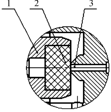
According to the practical requirements, the electromagnetic proportional valve is designed with a normal working pressure range of 5 ~ 20 MPa, the highest working temperature (+50 ℃) and the lowest temperature (-20 ℃). The structure of the solenoid proportional relief valve is shown in Figure 2.

1. proportional solenoid; 2. valve holder; 3.plunger rod;4.compression spring; 5.valve body; 6.guide sleeve;7.plunger seal unit; 8.valve port seal unit;9.valve head
The electromagnetic proportional pressure relief valve includes a proportional solenoid valve holder, valve holder, plunger rod, compression spring, valve body, guide sleeve, plunger seal untie, valve port seal unit, and a valve head.
3.1.1.Selection of proportional solenoid
The working principle of the proportional solenoid is as follows:for a given input current,the proportional solenoid will engender a certain displacement, the proportional solenoid will push rod to produce the same displacement and push the spool valve to move towards the head block of the valve with the decrease of opening degree and the system pressure will get increased. When the input current gets decreased, the displacement of the proportional solenoid will be decreased, under the action of spring force, the piston rod will produce a reverse displacement with the increase of opening degree and the system pressure will get decreased.
The design adopts the force-controlled proportional solenoid. The change of current in coil could adjust the output of electromagnetic force within the effective working stroke region of the solenoid armature. The rated current of the proportional solenoid is 0.8 A, the rated suction is 80 N and the rated travel is 3.6 mm.
3.1.2.The spring design calculations
The material of the valve spring is 60Si2Mn and the compression spring is designed to meet GB/T 12241—2005[3] and the both ends contact closely. The diameter of spring wire could be selected according to the following formula:
(1)
Where,Cis spring index;Kis curvature coefficient;P2is the maximum working load of the spring;[τ] is the allowable stress of spring material.
The number of spring active coils could be determined as follows:
(2)
Where,Gis the modulus of elasticity of spring material,λis the spring stiffness. The number of spring turns could be obtained:n1=n+2.
Based on the calculations, the parameters of the relief valve spring are as follows: the spring wire diameterd=1.5 mm, spring diameterD1=14 mm, height of the springH=15 mm, effective number of turns of the springn=4, the number of spring turnsn1=6.
3.1.3.Sealing design
Sealing structure of the electromagnetic proportional pressure relief valve includes both a valve port sealing unit and piston rod unit.
The contact sealing methods is adopted for the designing of the valve port and the valve port sealing structure is shown in Figure 3.
1.teflon;2.valve port; 3.seat
In order to obtain a good sealing performance, the sealing surfaces must have sufficient contact pressure. The desired contact pressure on the sealing material is related to material, width, surface roughness and medium pressure. With the limitations of the solenoid thrust, the sealing contact pressure can not be too high. In this design, comparative tests of the polyether ether ketone (PEEK) and the poly tetra fluoroethylene (PTFE) have been conducted to determine which one is more suitable material for the valve port with the same working width and roughness. The comparative results show that the hardness of PEEK material is too high while PTFE shows a good sealing performance.
The sealing between axial piston rod and the valve body adopts the canted coil Spring-energized Reciprocating. When the seal is assembled, the exposed edge of the canted coil spring contacts with the high pressure liquid. Such a sealing structure is shown in Figure 4.

1. rubber seals skeleton;2.inclined spring
The canted coil spring is embedded in the sealing region. The patented canted-coil spring provides a near-constant spring contact force over a wide range of working deflection. The structure of the dynamic sealing flange ring improves the sealing performance, strengthens the wipe function, and reduces the friction; therefore, a longer service life is expected.
In this design, the plunger rod and the valve body are made of stainless steel, surface finish is down to 1.6 μm. Tolerance of the plunger rod is g6, valve body is H7. Under the action of medium pressure, the canted spring in the seal tension to ensure the liquid not to leak to the outside of the high pressure valve through the interference-fit between the inner ring of the seal to the plunger rod and the outer ring to the valve body.
3.2.The characteristics of the electromagnetic proportional pressure valve
The characteristics of the electromagnetic proportional pressure relief valve are as follows: ① the proportional solenoid could make the output pressure controllable. It is also convenient to regulate the pressure; ② the range of output pressure could be continuously adjusted from 5 to 20 MPa; ③ by using the PID controlling proportional solenoid, the parameters of the PID could be adjusted according to the output pressure and the range of change is in a relative wide range; ④ the use of the canted coil Spring-energized Reciprocating enhances the sealing capability and wipe function, meanwhile it could reduce the friction and possess a longer service life.
4.The testing of the electromagnetic proportional pressure relief valve
沟道形成区西北侧以陡坡地貌为主,一般坡度为65°~85°,岸坡植被发育,灌、草均有生长,但由于斜坡较陡,具备崩塌、滑坡等不良地质现象发育的地形条件。沟道南东侧坡度稍缓,坡度为15°~30°,局部坡度为35°~65°;堆积有大量的松散的堆积体,最大的是沙沟滑坡。沙沟下游流通区段宽度较狭窄,宽度一般为15~30m。堆积区位于沙沟以下沟段,长度约0.4km,宽度约0.5km,面积约0.2km2,扇区堆积厚度10~15m,扇区泥石流堆积物方量约为200×104m3。
4.1.Testing purpose
The testing purposes of the electromagnetic proportional pressure relief valve are as follows: ① to test whether the accuracy of the pressure regulator or the pressure fluctuation range could meet the requirements of the instrument analysis; ② to test whether the service life of the valve is long enough to support the instrument working stably and reliably within the expected working life[4-5].
4.2.Testing device
Testing device consists of solvent reservoirs,high pressure bump, control board, touch screen, and high pressure pipelines[6-7]. The principle of the testing device is shown in Figure 5.
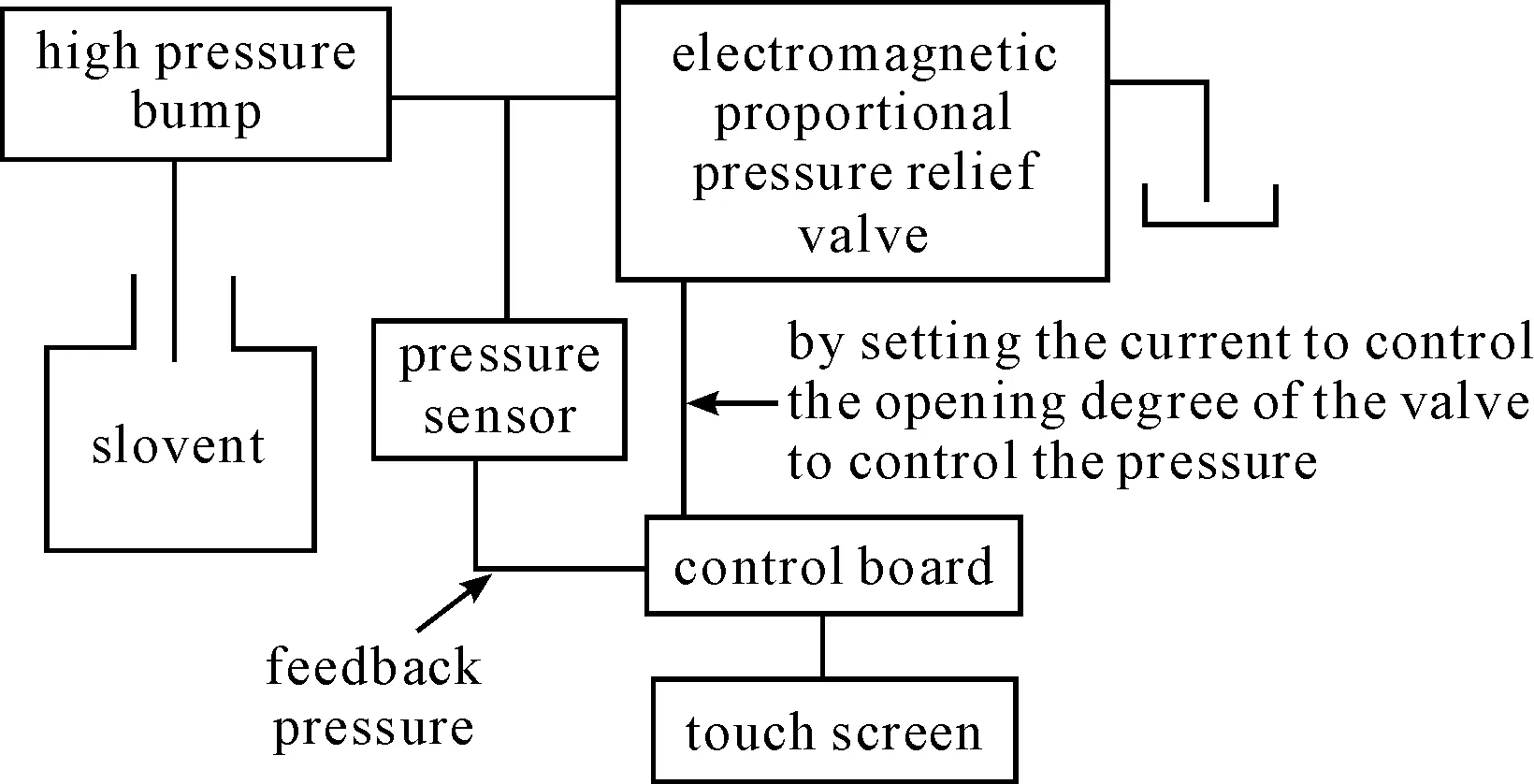
Figure 5. Principle of the testing device
4.3.Testing method and test results analysis
1) The testing method of pressure fluctuations: the desired pressure could be set through the “pressure setting” button of the testing device, and the fluctuation of actual pressure can be displayed dynamically on the screen. The measure points of 5 MPa, 10 MPa, 15 MPa, and 18 MPa are selected to test pressure fluctuations[8-10].
2) The testing method of the working life of the valve: for a given working pressure, the action time of electromagnet is set to test whether the pressure range of the relief current is within the maximum range of current for the solenoid. The maximum current of the electromagnet of the valve is 0.8 A, maximum output torque is 80 N and the working pressure is chosen as 15 MPa.
Based on the testing results as shown in Table 1, Table 2 and Figure 6, the following conclusions could be drawn: ① the design can fully meet the requirements of the pressure range of 0~20 MPa, with the pressure fluctuation of ± 1 MPa; ② electromagnetic proportional pressure relief valve acts 82,000 times and the controlled pressure accuracy of ±0.5 MPa meets the requirements. Since the action is evaluated 40 times per day, the valve life span will be more than five years.
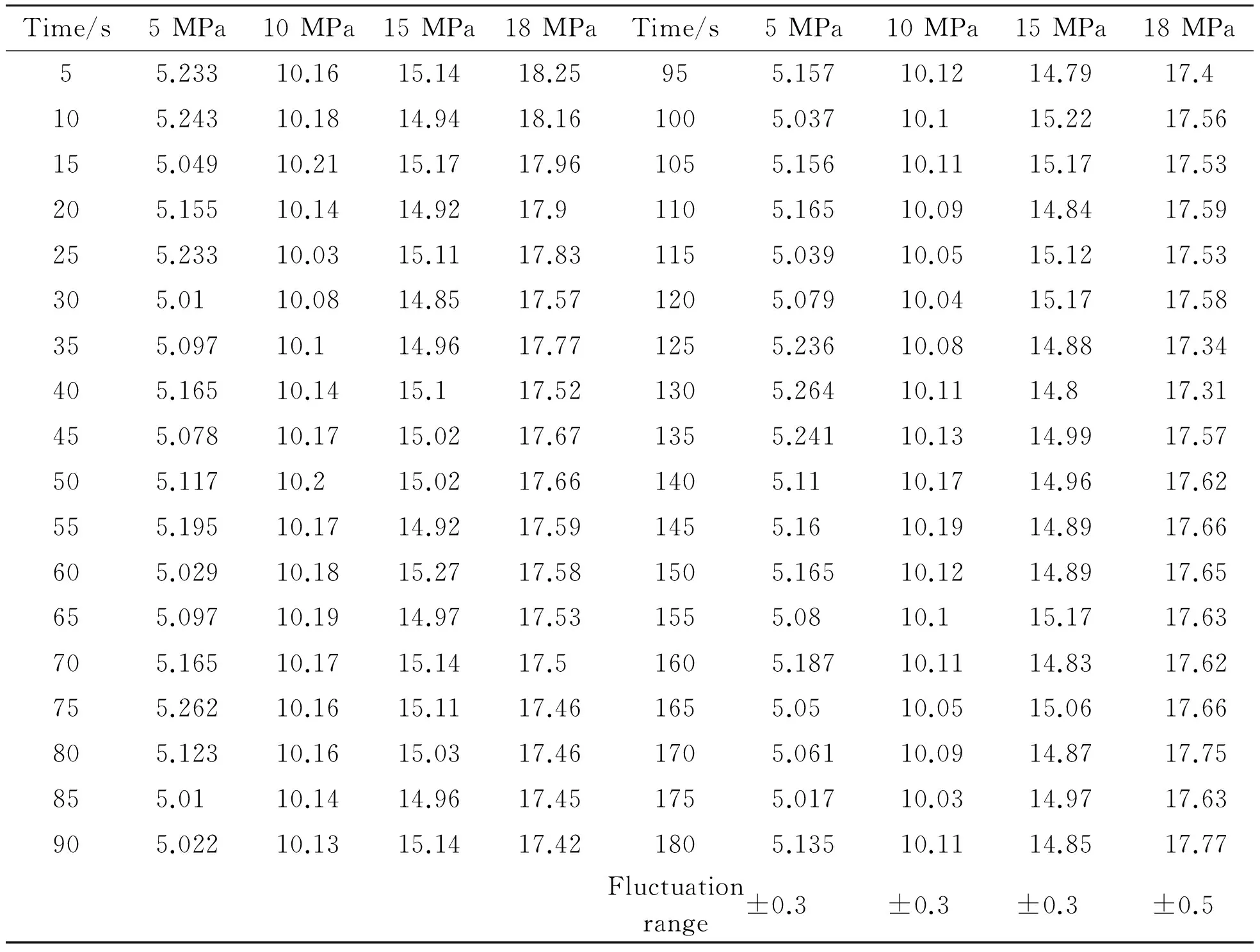
Table 1. Pressure fluctuation test results
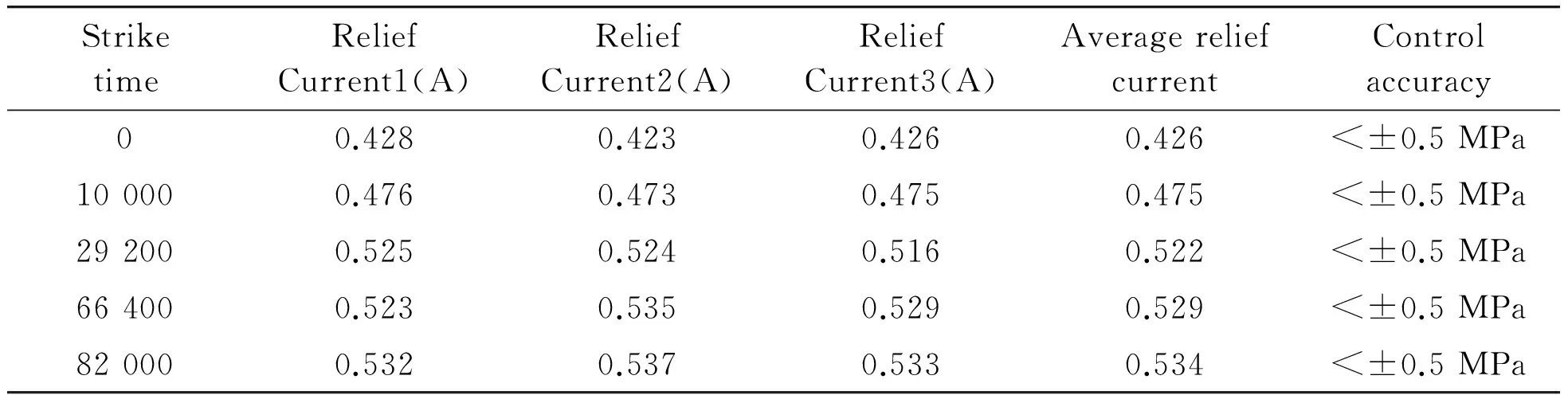
Table 2. Life test results
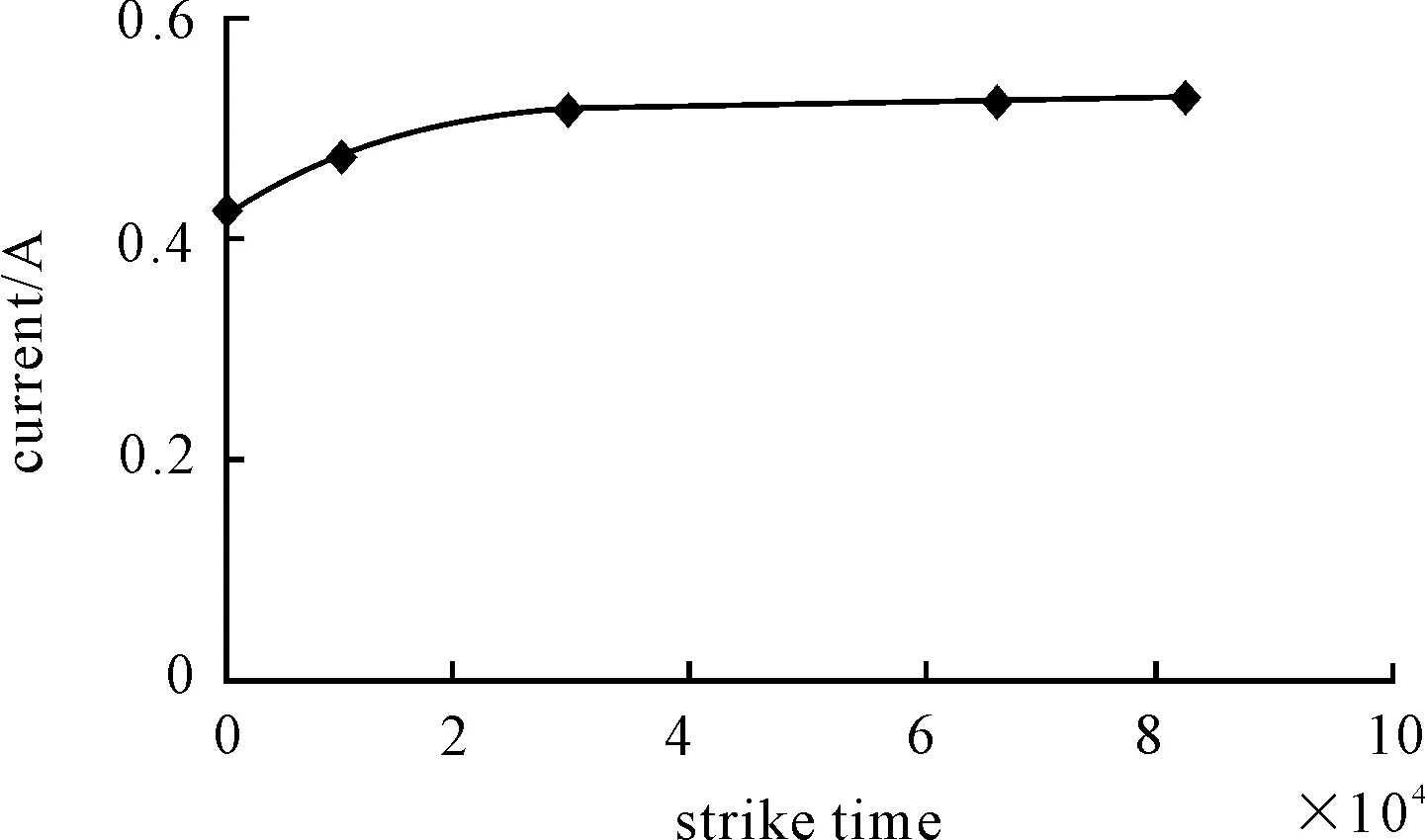
Figure 6. Service life testing curve
5.Conclusion
[1] Jiang Z,Yu L Y,Ke J.A research and development of the electromagnet on high speed proportion valve[J].Machinery Design & Manufacture,2005(5):1-3.
[2] Wang G H,Ling Y,Fan Q H.The design and experimental investigation of electri-hydraulic proportional valve[J].Experiments and measurements in fluid mechanics,2004,18(1):48-52.
[3] GB/T 12241—2005 Safety valves-General requirements[S].
[4] Wang X G,Chen W Q,Tang M F,et al.Testing and characteristics analysis of proportional solenoid valve[J].Journal of rocket propulsion,2011(4):52-59.
[5] Liu X,Nie W J.Design of Electromagnetic valve[J].Electric switchgear,2008(3):11-13.
[6] Wang R.Feasibility analysis of a test system of safety valve with large flow[J].Coal mining technology,2007(10):5-7.
[7] Zhang H,Wang J J,Ji Z B.Application analysis of design for safety valve systems[J].Chemical engineering design,2009,19(3):30-36.
[8] He M H.The solution of the vibration being happened in hydraulic system[J].Hydraulics pneumatics & seals,2007(3):37-38.
[9] Duan L J,Tao G,Meng F.Electro-mechanical converter dynamic analysis of high-speed proportional solenoid valve[J].Chinese Hydraulics & Pneumatics,2013(5):20-22.
[10]Yi J G.A computer testing approach for new electro-hydraulic proportional valve and its implementation[J].Machine tool & hydraulics,2013(4):101-103.
2014-03-10
10.3969/j.issn.1001-3881.2014.12.014
† Feng-xia HAN, E-mail:hfx80929@163.com
猜你喜欢
杂志排行
机床与液压的其它文章
- Influence of airflow uniformity over the duct outlet of vehicle air-condition on cooling performance*
- Design and realization of signal acquisition digital system for leak detection of water supply pipeline*
- Experimental study of chip formation and cutting force during
- Adaptive strategy of error anomaly processing in human simulated intelligent control*
- Phase-Lock technology of full digital UPS based on DSP*
- Software development for on-machine measurement of large CNC gear shape*