Developing deburring device based on burr formation principles*
2014-06-09LiJIChunlinZHANG
Li JI,Chun-lin ZHANG
1School of Mechanical Engineering,Shanxi Institute of Mechanical&Electrical Engineering,Changzhi046011,China;2Changzhi Hydraulic Co.LTD.,Changzhi046005,China
Developing deburring device based on burr formation principles*
Li JI†1,Chun-lin ZHANG2
1School of Mechanical Engineering,Shanxi Institute of Mechanical&Electrical Engineering,Changzhi046011,China;2Changzhi Hydraulic Co.LTD.,Changzhi046005,China
This paper introduces several deburring methods and then analyzes the reasons for burr formation in rotor parts and how to control them according to the processing crafts.It studies on the developing of deburring device based on electrochemical method and gives experimental proof.Finally it proves this method is efficient and high quality.
Cutting method,Removing the burr,Electrochemistry
The rotor parts are the main parts of vane pump,whose quality may directly affect the operation of the pump.The last process of rotor parts is to remove the burrs within and without the trough.If the burrs are not completely removed,the pump will wear out quickly and give noises,even stop working,which seriously affects the quality and life span of the oil pump[1].
According to a survey,the deburring devices used in China now can be divided into three groups:the first group is to manually use the triangle sharpening stone to remove the burrs.This method is demanding in labor and has low efficiency,at the same time it may damage the form of the rotor trough.The second group is to reform the current equipment into the special deburring devices or develop the deburring devices.Many domestic companies have made some helpful experiments in this field,such as Qinchuan Machinery reforming its current drilling machine into a deburring device,Yuxi Bearing using the current grinding machine to deburr the rotor parts,Qingjiang Hydraulic Machinery developing the gearelectrolyzing deburring device,Changjiang Hydraulic Machinery developing the gear-reversing deburring device[2-3].The third group is to purchase the special equipments to deburr.There are three kinds of deburring devices in the current market:one is to use the processing method such as the polishing equipments;another is to use the thermal energy to burn the burrs;still another is to use the electrochemistry method to corrode the parts.Nevertheless,all the deburring devices in the current market have such flaws as being high in price,complex in processing,and expensive in maintenance.
So,in order to avoid the above mentioned flaws,our project team attempts to develop a set of deburring device on the basis of studying the formation of the burrs and the deburring process.
1.The formation of burrs in rotor parts
1.1.The processing of rotor parts
The main technological requirements of rotor parts are to ensure the measurement precision of the inner circle and top circle,the surface roughness and the concentricity as well as to ensure no-burrs within and without the trough.The main process is as follows.
Processing the inner circle and the top circle ofthe rotor,the end faces(lathe)→processing the dowel hole(drill)→processing tank(mill)→heat treatment→accurate grinding the end faces→accurate grinding the groove→measurement and detection→deburring
As we can see,the deburring process,as the last process,plays a very important role in ensuring the product quality,whose results may directly decide the life span of the pump.
1.2.The formation of the burrs in lathing
As the rotor parts are plastic material(20CrMnTi),its burrs can be controlled in accurate lathing process.Based on the manufacturing process of the rotor parts,the burrs formed in rough processing of side faces can be removed by chamfering,while the burrs of the grooves can not be removed in this way.So a deburring process must be added after the accurate machining process(grinding).The following are the formation of the groove burrs.
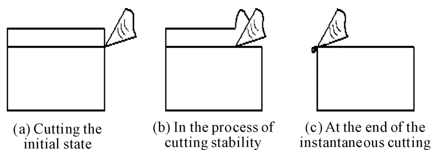
According to the theory of metal cutting,when the cutter gets away from the material,the original cutting layer suddenly turns thinner,and the stress of the cutting layer is smaller.Due to the pressing of the cutter,the root of swarf near the cutter’s edge undergoes plastic deformation,which causes the cutting forces turn to the feeding direction.The cutting layer will bend under this force,and the swarf root will also rebound due to unloading.At the moment the cutter and the metal material separates from each other,the swarf will slip due to the pressing of the cutter’s edge,but the root of swarf is still connected with the metal material.In this way,the burr will be formed on one side of the material being cut[4],as shown in Figure 1.

Figure 1.The formation of burrs
2.The electrochemistry deburring mechanism
According to the field measurement,the burrs in the rotor groove have small sizes(0.2~0.5 mm). So they can be removed by using electrochemical method.
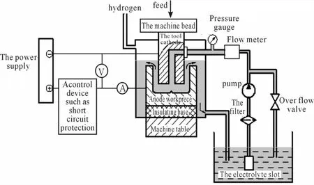
Electrolysis is a mature way of removing some material in the modern manufacturing.It is a craft to process the workpiece into certain shape and size,based on dissolving theory of the positive pole and by means of the formed negative pole(Figure 2).This processing method was put into use in USA and the Soviet Union in 1950s,and Japan improved the processing precision by inventing the gas-mixed electrolyzing machining in 1960s.

Figure 2.The processing principle of electrolysis
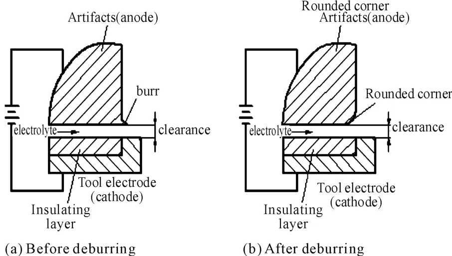
According to the electrochemistry reaction principle,the electric current density close to the angle of the positive pole of the workpiece is the highest. That is why the burrs will be quickly corroded and dissolved,and the angle of the workpiece will be quickly turned into circular one,as shown in Figure 3.Thus,the burrs will be dissolved and fall off from the root[5].

Figure 3.The principle of electrolyzing deburring
3.The device structure and technical requirements
Our project developed a set of specialized deburring clamp in order not to spill the electrolysis fluid around.The clamp is fixed in the fluid-flowing groove of the working platform of the special equipment.The design of the clamp and the negative polemust ensure the balanced flow of the electrolysis fluid,and at the same time ensure the reliable electrical conduction and the convenient installation.The processing gap between the negative pole and workpiece,after several experiments,is set to be 0.6 mm.The negative pole aims at the root of burrs.The connecting part of the workpiece and the positive pole tends to be corroded so that effective measures must be taken,which is usually done by painting epoxy resin or epoxy polyester.
This part is deburred by using the direct current and the working voltage is of 12~14 V,with the electrical current density of 15~20 A/cm2,the electrolysis fluid pressure 0.15 MPa,the electrolysis fluid temperature of25~30℃,and the deburring time spent on each workpiece of 6~7 s.Six workpieces are processed at the same time and the burrs are removed thoroughly.The structure of the rotor parts is not complex but there are a large amount of burrs and the precision requirements are rather high.This processing method leaves 45°circular angle at the burr positions while deburring,guaranteeing the product quality,as shown in Figure 4.

Figure 4.The rotor parts after deburring
This deburring method is low in cost,simple in device structure,and highly extendable.The maintenance fee is low.
4.The features of electrolysis deburring
Compared with the crafts such as machining deburring and thermal energy deburring,the electrolysis deburring has the following advantages:
1)It can remove the burrs in hard-to-reach locations(such as small grooves).
2)It can remove all the burrs in different locations of the parts at one time and it can remove the burrs and smoothing the angle at the same time.
3)It is high in efficiency by working on several workpieces at the same time and operating automatically.
4)It can deburr selectively on the condition that it does not affect the adjacent surfaces.
5)It will not generate the residual stress and second-time burr,nor the mechanical deformation and thermal deformation.
In application,this deburring method also has certain limitations.
①It is high in cost,mainly due to the manufacturing of specialized electrode and clamp.In order to avoid corrosion and improve life span,the positive pole of electrode has to be painted.
②It is strict in craft.The requirements on the sizes of burrs are strict.When the burr is too big in size,a pre-process has to be added before processing to roughly removing the burr in case of the short circuit of electrode and parts.
③The parts after deburring have to be cleaned properly and undergone the rust-proof treatment because the parts have been soaked in electrolytic solution and become corrosion-inclined.
5.Conclusion
The modern products have put increasingly higher requirements on the quality of parts surface so that deburring has become one indispensable step in parts processing.This project has developed the rotor parts specialized deburring device,which is highly extendable and marketable.It can remove burrs in different parts by just making different electrodes and adjusting the gap and the matching of electrolytic solution. Therefore,it is highly competitive in the market.
[1] Luyulin.YB vane pump rotor slot deburring machine[J].Machine Tool&Hydraulics,1984(6):89.
[2] Wang chunfeng.The manufacture of a deburring machine[J].Machinery Workers,2005(8):46.
[3] Ye yinsen.Glitch detection methods and selection Discussion[J].Machine Tool&Hydraulics,1996(1):85.
[4] Chang haiping.In the process ofmetal cutting burr control[J].Mechanical Management and Development,2003(8):26.
[5] Shen jian.Electrochemical deburring of precision aluminum parts[J].Light Alloy Fabrication Technology,1998(8):45.
摘要:分析了数控切割机自动调高器设计的技术难点和技术性能要求,设计了以运算法电容检测技术为核心的自动调高器微电容检测电路,并对所设计的电路进行了仿真分析和试验验证。结果表明:所设计的电路具有良好的检测精度,较快的动态响应速度,良好的稳定性和较强的噪声抑制能力,满足实际需求。
关键词:数控切割机;自动调高器;电容
中图分类号:TM934.23
基于零件毛刺形成机理开发去除毛刺设备*
吉 丽†1,张春林2
1.山西机电职业技术学院机械工程系,山西长治 046011
2.长治液压有限公司,山西长治 046005
介绍了几种常见的去除毛刺方法,结合毛刺形成机理,根据加工零件的生产工艺,对转子零件产生毛刺的原因和控制方法作出分析,最后利用电化学法开发了去除毛刺的专业设备,并进行了实验验证。结果表明:该设备去除毛刺的效率高、质量好。
切削方法;去除毛刺;电化学法
TG234.2
基于微电容检测技术的数控切割机自动调高系统研究*
邹爱成†,王群英,张 云
桂林航天工业学院,广西桂林 541004
10.3969/j.issn.1001-3881.2014.18.023
2014-06-15
*Project supported by Changzhi City Science and Technology Innovation Project(1000098)
†Li JI,E-mail:jili_cz@126.com
猜你喜欢
杂志排行
机床与液压的其它文章
- Design and application of attitude measuring device for DC power output filter circuit
- Experimental study on milling tool life for SKD11 steel and optimization of cutting parameters*
- Application research on three-phase inverter with space-vector pulse modulation*
- Glowworm swarm optimization algorithm merging simulated annealing strategy*
- Comprehensive obstacle avoidance system based on the fuzzy control for cleaning robot
- Implementation of wireless communication and real time control for CNC system of embedded CNC turret punch press*
