煤层气水力压裂缝内变密度支撑剂运移规律
2014-06-07杨尚谕杨秀娟闫相祯许建国
杨尚谕,杨秀娟,闫相祯,许建国,樊 恒
(1.中国石油大学(华东)油气CAE技术研究中心,山东青岛 266580;2.吉林油田公司采油工艺研究院,吉林松原 138000)
煤层气水力压裂缝内变密度支撑剂运移规律
杨尚谕1,杨秀娟1,闫相祯1,许建国2,樊 恒1
(1.中国石油大学(华东)油气CAE技术研究中心,山东青岛 266580;2.吉林油田公司采油工艺研究院,吉林松原 138000)
针对煤层气水力压裂有效支撑缝长过短且缝内铺砂浓度分布不均匀的问题,研究变密度支撑剂颗粒在裂缝内的运移规律。采用Pseudo Fluid模型考虑了裂缝内支撑剂颗粒之间的相互影响,借助Visual Studio 2012设计平台编制相应计算软件,并通过与现场监测值进行对比,校核了软件计算的准确性。讨论了压裂液黏度、裂缝壁面、排量和支撑剂密度等参数对缝内铺砂浓度和有效支撑缝长影响规律,分析了超低密度支撑剂在不同围压和温度工况下的破碎率。结果表明:坚果壳支撑剂在围压为69 MPa、环境温度为90℃工况下破碎率<2%,满足现场需求;随着压裂液黏度、施工排量增加,裂缝支撑长度增加,缝内铺砂更加均匀;支撑剂颗粒直径增加使得裂缝支撑长度降低;采用变密度支撑剂较单一陶粒砂有效支撑半缝长增加了19.5 m,且铺砂效果更均匀。
煤层气井;变密度支撑剂;分段压裂;支撑剂运移
伴随国内油气需求的持续增长与常规油气产量的不断下降,具有较大资源潜力的非常规油气逐渐成为新的领域,受到各个国家和油气公司的高度重视[1]。我国经过20 a的研究探索,实际钻完煤层气井近万口,但仍存在大批煤层气井产量低或者产出的气不具备工业产能,直接影响了我国煤层气开采的发展[2-4]。大量现场压裂井监测数据结果表明,煤层气低产井压裂诱导裂缝内支撑剂颗粒由于密度较高而大量沉积在近井端0~40 m范围内,有效支撑缝长较短是影响煤层气井压裂产能的主要原因之一[5-8]。
由Stokes定律可知清水携砂颗粒以抛物线方式下沉结合砂提翻滚,携砂距离较短,铺砂近井厚度较大,远井厚度小,有效支撑短[9-10]。Liu和Sharma等[11-14]通过实验的方式对支撑剂颗粒在裂缝内的运移规律进行研究,结果表明,支撑剂颗粒速度改变取决于支撑剂颗粒直径与该位置处裂缝宽度的比值,当该比值接近1时,支撑剂颗粒沿缝长方向速度将急剧下降。Staben等[15-17]提出采用两平行板代替裂缝壁进行支撑剂颗粒运移规律研究,未考虑裂缝宽度变化对颗粒运移速度的影响。
国外学者提出的超低密度支撑剂技术可以使得携砂距离增加,有效支撑长度变长,裂缝导流能力增加,但超低密度支撑剂价格昂贵,不适合大面积投入使用。
综上分析,针对煤层气水力压裂支撑剂密度较高使得缝内携砂距离偏短的问题,笔者提出采用高密度支撑剂与超低密度支撑剂混合的方法进行压裂,研究了变密度支撑剂在压裂裂缝内的运移规律,并通过实验验证了该超低密度支撑剂满足现场抗压性能及破碎率要求。该方法增加了裂缝有效支撑长度,提高了煤层气井产能,为煤层气低产井、老井重复压裂提供技术支持。
1 低密度坚果壳支撑剂力学性能
将坚果壳制成支撑剂首先要考虑的问题就是当支撑剂被输送到诱导裂缝内时,该支撑剂是否能抵抗地层闭合压力而继续起到支撑作用,通过实验对其抗压强度和破碎率进行测试,图1为坚果壳支撑剂试样。
本实验针对两种密度的干燥支撑剂:①ULW1体积密度0.8 g/cm3(视密度1.20 g/cm3);②ULW2体积密度1.25 g/cm3(视密度1.75 g/cm3)。研究20/40目坚果壳支撑剂颗粒在20℃和90℃时的抗挤压强度及破碎率情况,ULW1支撑剂实验结果表明:当闭合压力达到100 MPa,支撑剂颗粒ULW1在 20℃时振筛10 min后支撑剂颗粒破碎率分别为1.41%,1.33%,1.59%和1.36%,由图2(a)中支撑剂颗粒应力-应变关系曲线得到坚果壳支撑剂弹性模量为172.42 MPa;当温度升高到90℃后,如图3(a)所示,振筛10 min后支撑剂颗粒破碎率分别为1.47%,1.64%,1.93%和1.85%,90℃时对应坚果壳支撑剂弹性模量为137.93 MPa;温度升高,ULW1破碎率增大,弹性模量降低。
ULW2支撑剂抗压实验选取3组颗粒试样进行测试,结果表明:当闭合压力达到100 MPa,ULW2支撑剂在20℃时振筛10 min后颗粒破碎率分别为4.02%,6.38%和6.95%,支撑剂弹性模量为344.83 MPa,如图2(b)所示;当温度升高到90℃后,振筛10 min后支撑剂颗粒破碎率分别为5.29%, 7.90%和7.32%,该工况下支撑剂弹性模量为275.86 MPa,如图3(b)所示;温度升高,ULW1破碎率增大,弹性模量降低。对比发现ULW2在闭合压力为100 MPa工况下颗粒破碎率较大,降低闭合压力到69 MPa,重做实验,结果表明,3组试样90℃时最大破碎率为2.0%,满足现场煤层气水力压裂支撑剂抗压及破碎率性能指标。

图1 坚果壳支撑剂试样Fig.1 Proppant sample of nut shell
2 变密度支撑剂在诱导裂缝内运移规律
2.1 基于Pseudo Fluid模型的裂缝等效宽度计算
煤层气水力压裂诱导裂缝中,由于支撑剂密度、压裂液黏度的影响,支撑剂颗粒之间会存在相互拖拽的现象使得支撑剂在x,y方向上的速度发生改变(图4)。

图2 低密度支撑剂(0.8,1.25 g/cm3)20℃时的强度试验曲线Fig.2 Strength test curves of the low-density proppant(0.8,1.25 g/cm3)at 20℃

图3 低密度支撑剂(0.8,1.25 g/cm3)90℃时的强度试验曲线Fig.3 Strength test curves in of the low-density proppant(0.8,1.25 g/cm3)at 90℃

图4 支撑剂颗粒运移轨迹及裂缝边界示意Fig.4 Diagram of the proppant particle motion and fracture boundary
诱导裂缝内动力流体悬浮颗粒之间相互作用非常复杂,研究某一支撑剂颗粒周围粒子对其影响规律只在非常有限的工况下才可以实现。笔者采用经过简化的半经验Pseudo Fluid模型对其求解,该模型利用等效裂缝宽度来近似模拟变密度支撑剂颗粒相互影响效果。支撑剂颗粒在诱导裂缝内流动时,由于支撑剂浓度不为0而引起的附加流体拖拽力使得裂缝宽度发生变化,裂缝宽度改变量wc可通过式(1)[18]计算得到,即

式中,wc为附加拖拽力而引起的裂缝宽度变化量,m; c为t时刻携砂液中支撑剂体积分数;dp为支撑剂颗粒直径,m;w为支撑剂颗粒位置处裂缝宽度,m。
水力压裂裂缝的等效宽度weff可以表述[19]为

式中,weff为Pseudo Fluid模型对应的裂缝等效宽度,m。
2.2 裂缝内流体流动方程
煤层气水力压裂诱导主裂缝呈细长型,忽略缝内流体压力在宽度方向(图4中z向)上的变化。因此,裂缝内的压裂液流动过程可以通过缝内流体二维流

式中,vx,vy为压裂液在x,y方向上的速度分量, m/min;qL为滤失速度,m/min。
2.3 缝内支撑剂运移方程
诱导裂缝内携砂液质量守恒方程[23]为动模型[20-22]描述,即

式中,ρ为携砂液密度,kg/m3;v为携砂液速度, m/min;ρF为流体密度,kg/m3;QL为滤失量,m3。
变密度支撑剂颗粒质量守恒方程[24]为

式中,ρp为变密度支撑剂等效密度,kg/m3;vp为支撑剂颗粒速度,m/min。
在携砂液中,由于支撑剂密度和黏性力的影响,支撑剂颗粒的水平速度小于携砂液的移动速度。因此,要精确的计算裂缝内铺砂浓度,必须分析出支撑剂在缝内的运移速度。
支撑剂颗粒运移速度[25-26]为

式中,vt为修正后的Stoke颗粒沉降速度,m/min;kwc为支撑剂和压裂液沿缝长方向上平均速度的比值。

式中,vp为支撑剂颗粒x向平均速度,m/s;vf为压裂液的平均速度m/s;
修正后的Stoke沉降速度vt通过式(8)求得
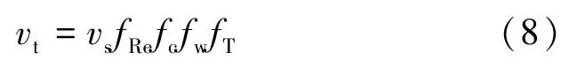
式中,vs为Stoke沉降速度,m/min;fRe为惯性效应修正系数,无因次;fc为缝内支撑剂浓度效应修正系数,无因次;fw为壁面效应修正系数,无因次;fT为湍流扰动修正系数,无因次。
联立方程(4)~(6)得到诱导裂缝内变密度支撑剂运移方程,即

方程(9)对应的边界条件(图4)为
l2边界上:

l1和l3边界上:

诱导裂缝内流体压力、裂缝宽度和缝内支撑剂浓度计算相互依存,想要同时求解难度较大。笔者在计算诱导裂缝内速度场时忽略缝内流体压力和裂缝宽度变化对支撑剂运移规律的影响,假定支撑剂在每个时间步内的运移过程是准稳态,即在任意时间步内,支撑剂运移速度的改变不直接影响缝内流体速度变化。
在初始支撑剂浓度的基础上对缝内压力和有效裂缝宽度进行迭代求解,当该迭代计算收敛,利用裂缝尺寸和流体速度求解变密度支撑剂运移方程(9),得到下一步迭代计算的支撑剂浓度值,持续迭代计算,直到最终收敛,确定裂缝内支撑剂浓度的最终分布。
3 实例分析及结果讨论
以宁武盆地W8-3井为例,表1为煤储层物理力学参数。

表1 W8-3井煤储层基本参数Table 1 Fracturing parameters of coal reservoir
3.1 煤层气水力压裂裂缝形状及几何尺寸计算
采用自编3D-CBMulti-Fracture软件,对该区块W8-3煤层气井水力压裂裂缝几何形状进行预测。压裂设计方案:压裂液施工排量6.5 m3/min,平均砂比12%,最高砂比25%~30%,携砂液用量390 m3,支撑剂用量46.8 m3,前置液用量303.3 m3,顶替液17.9 m3。图5为W8-3井第2段裂缝几何尺寸及缝内压力分布云图,裂缝有效半长70.6 m,最大缝宽为9.54 mm,缝内最大净压力为20.60 MPa,上半缝高9.05 m,下半缝高3.96 m,与现场微地震监测结果对比误差为3.06%。煤层气水力压裂过程中,底层与产层的最小主应力相差小,裂缝向下延伸严重;盖层与产层应力相差大,裂缝向上延伸受阻,缝内净压力增加,使得裂缝向下延伸。
3.2 缝内变密度支撑剂铺砂浓度影响因素
忽略压裂施工参数的改变对诱导裂缝几何形状的影响,对比图6计算结果表明裂缝壁对支撑剂运移速度影响较大,对于W8-3第2段裂缝,由于裂缝壁的影响,支撑半缝长度从47.67 m减小到30.85 m,支撑缝高从10.41 m减小到9.32 m。

图5 W8-3井第2段裂缝几何尺寸及缝内压力分布云图Fig.5 Effective fracture geometry and pressure contours of W8-3 well’s the 2nd crack

图6 压裂液黏度为10 mPa·s,不考虑和考虑裂缝壁时缝内支撑剂铺砂浓度分布云图Fig.6 Proppant concentration contour map without wall and with wall for 10 mPa·s fluid
随着压裂液黏度增加,裂缝支撑缝高增大,裂缝壁的存在使得支撑剂颗粒附加拖拽力减小,从而促使支撑剂平均速度大于压裂液平均流速,即裂缝有效支撑长度和支撑高度均增加,如图7(a)所示。图8为现场测试数据与软件模拟结果对比发现当压裂液黏度小于255 mPa·s时,软件模拟结果偏保守,而当压裂液黏度大于255 mPa·s时,软件计算结果较实际情况略高,但最高误差小于10%,计算精度满足工程要求。

图7 压裂液黏度为500 mPa·s,考虑裂缝壁时缝内支撑剂(40/70,20/40)铺砂浓度分布云图Fig.7 Proppant(40/70,20/40)concentration contour map with wall for 500 mPa·s fluid

图8 压裂液黏度与裂缝有效支撑长度关系曲线Fig.8 Relationship between fluid viscosity and crack effective length
图7对比表明:支撑剂颗粒的直径增加促使压裂液拖拽力增加,从而使得支撑剂阻力增加,由于支撑剂颗粒沿裂缝x方向的速度分量减小,因此,支撑剂颗粒直径从(40/70)目增加到(20/40)目裂缝支撑长度迅速降低。
忽略施工排量改变对裂缝形状的影响,图9为施工排量对压裂诱导裂缝内支撑剂铺设浓度的影响,结果表明:施工排量增加1倍使得沿缝长方向压降速度增加,缝内支撑剂分布合理且有效支撑缝长增大0.41倍。
图10为不同密度支撑剂工况下对应诱导裂缝有效半缝长,采用变密度支撑剂有效支撑半长达到44.5 m,较单一陶粒砂有效支撑半缝长增加了19.5 m,且铺砂效果更均匀,将极大的提高煤层气产能。

图9 施工排量为4,8 m3/min时缝内铺砂浓度Fig.9 Proppant placement concentration for the pumping rate 4,8 m3/min
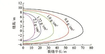
图10 不同密度支撑剂裂缝有效支撑长度Fig.10 Effective support length of different fracture proppant density
4 结 论
(1)在围压为69 MPa、环境温度为90℃工况下,坚果壳支撑剂破碎率<2%,满足现场规定支撑剂使用要求。
(2)利用Pseudo Fluid模型研究变密度支撑剂颗粒之间相互影响,研究表明压裂液黏度、裂缝壁面、支撑剂粒径、排量和支撑剂密度等因素将直接影响诱导裂缝内铺砂浓度的分布,进而影响压裂裂缝导流能力。
(3)与单一陶粒砂相比,使用变密度支撑剂有效支撑半缝长增加了19.5 m,且缝内铺砂更为均匀,极大地提升了煤层气产量。
[1] 邹才能,朱如凯,吴松涛,等.常规与非常规油气聚集类型、特征、机理及展望——以中国致密油和致密气为例[J].石油学报,2012,33(2):173-186.
Zou Caineng,Zhu Rukai,Wu Songtao,et al.Types,characteristics, genesis and prospects of conventional and unconventional hydrocarbon accumulations:Taking tight oil and tight gas in China as an instance[J].Acta Petrolei Sinica,2012,33(2):173-186.
[2] Ye Zhihui,Chen Dong,Wang J G.Evaluation of the non-Darcy effect in coalbed methane production[J].Fuel,2014,121(1):1-10.
[3] Aditya Khanna,Alireza Keshawarz,Kate Mobbs,et al.Stimulation of the natural fracture system by graded proppant injection[J].Journal of Petroleum Science and Engineering,2013,15(7):1-7.
[4] Dae Sung Lee,Derek Elsworth,Hideaki Yasuhara,et al.Experiment and modeling to evaluate the effects of proppant-pack diagenesis on fracture treatments[J].Journal of Petroleum Science and Engineering,2010,74(2):67-76.
[5] Luiz Bortolan Neto,Andrei Kotousov.Residual opening of hydraulic fractures filled with compressible proppant[J].International Journal of Rock Mechanics and Mining Science,2013,61(7):223-230.
[6] 闫相祯,张衍涛,杨秀娟,等.煤层气多分支水平井完井管柱许可造斜率设计[J].煤炭学报,2010,35(5):787-791.
Yan Xiangzhen,Zhang Yantao,Yang Xiujuan,et al.Permitted buildup rate of completion strings in multi-branch CBM well[J].Journal of China Coal Society,2010,35(5):787-791.
[7] Rahman M M.A review of hydraulic fracture models and development of an improved pseudo-3D model for stimulating tight oil&gas sand[J].Energy Sources Part A,2010,32(14):16-36.
[8] Kotousov A,Bortolan Neto L,Rahman S S.Theoretical model for roughness induced opening of cracks subjected to compression and shear loading[J].Int.J.Fract.,2011,172(2):9-18.
[9] Bortolan Neto L,Kotousov A,Bedrikovetsky P.Application of contact theory to evaluation of elastic properties of low consolidated porous media[J].Int.J.Fract.,2011,168(2):67-76.
[10] Bortolan Neto L,Kotousov A,Bedrikovetsky P.Elastic properties of porous media in the vicinity of the percolation limit[J].J.Pet.Sci.Eng.,2011,78(3):28-33.
[11] Liu Y,Sharma M M.Effect of fracture width and fluid rheology on proppant settling and retardation:An experimental study[J].SPE 96208,2005.
[12] Adachi J,Siebrits E,Peirce A,et al.Computer simulation of hydraulic fractures[J].Int.J.Rock Mech.Min.Sci.,2007,44(7): 39-57.
[13] Adachi J I,Detournay E,Peirce A P.Analysis of the classical pseudo-3D model for hydraulic fracture with equilibrium height growth across stress barriers[J].Int.J.Rock Mech.Min.Sci.,2010,47 (6):25-39.
[14] Chekhonin E,Levonyan K.Hydraulic fracture propagation in highly permeable formations,with applications to tip screenout[J].Int.J.Rock Mech.Min.Sci.,2012,50(2):19-28.
[15] Staben M E,Zinchenko A Z,Davis R H.Motion of a particle be-tween two parallel plane walls in low reynolds number poissuille flow[J].Physics of Fluids,2003(6):1711-1731.
[16] Zhang X,Jeffrey R G,Bunger A P,et al.Initiation and growth of a hydraulic fracture from a circular wellbore[J].Int.J.Rock Mech.Min.Sci.,2011,48(9):84-95.
[17] Kotousov A.Fracture in plates of finite thickness[J].Int.J.Solids Struct.,2007,44(8):59-73.
[18] Codrington J,Kotousov A.Application of the distributed dislocation technique for calculating cyclic crack tip plasticity effects[J].Fatigue Fract.Eng.Mater.Struct.,2007,30(11):82-93.
[19] Codrington J,Kotousov A.The distributed dislocation technique for calculating plasticity induced crack closure in plates of finite thickness[J].Int.J.Fract.,2007,144(2):85-95.
[20] Aghighi MA,Rahman S S.Initiation of a secondary hydraulic fracture and its interaction with the primary fracture[J].Int.J.Rock Mech.Min.Sci.,2010,47(7):14-22.
[21] 闫相祯,宋根才,王同涛,等.低渗透薄互层砂岩油藏大型压裂裂缝扩展模拟[J].岩石力学与工程学报,2009,28(7):1425-1431.
Yan Xiangzhen,Song Gencai,Wang Tongtao,et al.Simulation of fracture propagation in large-scale reservoir with low permeability and thin interbedded sandstone[J].Chinese Journal of Rock Mechanics and Engineering,2009,28(7):1425-1431.
[22] 闫相祯,王保辉,杨秀娟,等.确定地应力场边界载荷的有限元优化方法研究[J].岩土工程学报,2010,32(10):1485-1490.
Yan Xiangzhen,Wang Baohui,Yang Xiujuan,et al.Finite element optimization method of boundary load of in-situ stress field[J].Chinese Journal of Geotechnical Engineering,2010,32(10): 1485-1490.
[23] 张 毅,闫相祯,颜庆智.三维分层地应力模型与井眼岩石破裂准则[J].西安石油学院:自然科学版,2000,15(4):42-44.
Zhang Yi,Yan Xiangzhen,Yan Qingzhi.3D Model for the stratified calculation of ground stress and fracture criterion of wellhole rock [J].Journal of Xi’an Petroleum Institute(Natural Science Edition),2000,15(4):42-44.
[24] Felice R D.The particle in a tube analogy for a multiparticle suspension[J].International Journal of Multiphase Flow,1996,22 (3):515-525.
[25] Allan R Rickards,Harold D Brannon,William D Wood,et al.High strength,ultralightweight proppant lends new dimensions to hydraulic fracturing applications[J].SPE 84308,2006.
[26] 王 雷,张士诚.压裂液返排速度对支撑剂回流量及其在缝内分布的影响[J].油气地质与采收率,2008,15(1):101-102.
Wang Lei,Zhang Shicheng.Influence of the backflow velocity of fracturing on the backflow volume and distribution of proppant in fractures[J].PGRE,2008,15(1):101-102.
Variable density proppant placement in CBM wells fractures
YANG Shang-yu1,YANG Xiu-juan1,YAN Xiang-zhen1,XU Jian-guo2,FAN Heng1
(1.Oil and Gas CAE Technology Research Center,China University of Petroleum,Qingdao 266580,China;2.Oil Production Technology Research Institute of Jilin Oilfield Company,Songyuan 138000,China)
The migration law in the cracks of variable density proppant particles had been researched,for effective support fracture length of CBM hydraulic fracturing was too short and seam sanding concentration distributed uneven.The mutual influence of the fracture proppant particles was considered using Pseudo Fluid model,and the corresponding calculation software was written with the Visual Studio 2012 design platform,then the accuracy of the calculations was checked through comparison with the value of field monitoring software.The effective law to seam sanding concentration and effective support slot length of the fracturing fluid viscosity,wall cracks,displacement and proppant density parameters were discussed,and the broken rate of the ultra-low density proppant was analyzed at different confining pressure and temperature conditions.The results show that broken rate of a nut shell proppant is less than 2%in the condition of confining pressure 69 MPa and the ambient temperature 90℃,which meet the site requirements;With the increase of fracturing fluid viscosity,the construction displacement and fracture bracing length,the seam sanding is more uniform;with the proppant particle diameter increases,the crack support length decreases;compared to single ceramic sand,using variable-density proppant makes effective support half-slot length increasing 19.5 m,and the sanding effect is more uniform.
coalbed methane well;variable density proppant;staged fracturing;proppant migration
P618.11;TE371
A
0253-9993(2014)12-2459-07
2013-11-15 责任编辑:韩晋平
国家自然科学基金资助项目(51374228,51105381);中央高校基本科研业务费专项资金资助项目(27R1315018A)
杨尚谕(1986—),男,陕西榆林人,博士研究生。E-mail:shangyuy@163.com
杨尚谕,杨秀娟,闫相祯,等.煤层气水力压裂缝内变密度支撑剂运移规律[J].煤炭学报,2014,39(12):2459-2465.
10.13225/j.cnki.jccs.2013.1693
Yang Shangyu,Yang Xiujuan,Yan Xiangzhen,et al.Variable density proppant placement in CBM wells fractures[J].Journal of China Coal Society,2014,39(12):2459-2465.doi:10.13225/j.cnki.jccs.2013.1693
