Numerical prediction of 3-D periodic flow unsteadiness in a centrifugal pump under part-load condition*
2014-06-01PEIJi裴吉YUANShouqi袁寿其LIXiaojun李晓俊YUANJianping袁建平
PEI Ji (裴吉), YUAN Shou-qi (袁寿其), LI Xiao-jun (李晓俊), YUAN Jian-ping (袁建平)
National Research Center of Pumps, Jiangsu University Zhenjiang 212013, China, E-mail: jpei@ujs.edu.cn
Numerical prediction of 3-D periodic flow unsteadiness in a centrifugal pump under part-load condition*
PEI Ji (裴吉), YUAN Shou-qi (袁寿其), LI Xiao-jun (李晓俊), YUAN Jian-ping (袁建平)
National Research Center of Pumps, Jiangsu University Zhenjiang 212013, China, E-mail: jpei@ujs.edu.cn
(Received August 20, 2013, Revised January 12, 2014)
Numerical simulation and 3-D periodic flow unsteadiness analysis for a centrifugal pump with volute are carried out in whole flow passage, including the impeller with twisted blades, the volute and the side chamber channels under a part-load condition. The pressure fluctuation intensity coefficient (PFIC) based on the standard deviation method, the time-averaged velocity unsteadiness intensity coefficient (VUIC) and the time-averaged turbulence intensity coefficient (TIC) are defined by averaging the results at each grid node for an entire impeller revolution period. Therefore, the strength distributions of the periodic flow unsteadiness based on the unsteady Reynolds-averaged Navier-Stokes (URANS) equations can be analyzed directly and in detail. It is shown that under thedes.0.6Q condition, the pressure fluctuation intensity is larger near the blade pressure side than near the suction side, and a high fluctuation intensity can be observed at the beginning section of the spiral of the volute. The flow velocity unsteadiness intensity is larger near the blade suction side than near the pressure side. A strong turbulence intensity can be found near the blade suction side, the impeller shroud side as well as in the side chamber. The leakage flow has a significant effect on the inflow of the impeller, and can increase both the flow velocity unsteadiness intensity and the turbulence intensity near the wall. The accumulative flow unsteadiness results of an impeller revolution can be an important aspect to be considered in the centrifugal pump optimum design for obtaining a more stable inner flow of the pump and reducing the flow-induced vibration and noise in certain components.
numerical prediction, flow unsteadiness, turbulence intensity, centrifugal pump with volute
Introduction
The centrifugal pump is one of the most important energy conversion device widely used in almost all industrial and agricultural applications: including the nuclear industry, the petroleum industry, the agribusiness, the chemistry industry, as well as the cryogenic propellant pumping. The complex inner flow in the centrifugal pump, with a strong rotor-stator interaction, can generate hydraulic excitation forces and give rise to pressure pulsations, especially under a part-load condition. These dynamic pressures then will lead to mechanical vibrations and alternating stresses in various pump components, called the flow-induced vibration[1]. The vibrations transmitted to the foundations can spread as the solid-borne noise throughout the building, and the vibrating pump structures can also radiate air-borne and fluid-borne noises.
This periodical rotor-stator interaction involves two kinds of effects, as discussed by Feng et al.[2]. The first is the downstream effect of the impeller on the stator flow, which is characterized by unsteady effects due to the highly distorted relative impeller flow field and impeller wakes. The second is the upstream effect of the stator on the impeller flow, which causes unsteady pressures and velocity fluctuations to the relative flow. This unsteady effect was studied both numerically and experimentally, and most of the investigations focus on the radial diffuser pumps because of the multi-vanes of both the rotor and the stator and the more complicated mechanism. Shi and Tsukamoto[3]made calculations based on the three dimensional unsteady Reynolds-averaged Navier-Stokes (URANS) equations with standard turbulence models within an entire stage of a diffuser pump to investigate the pressure fluctuations due to the interaction between impeller and diffuser vanes. He et al.[4]calculated the 3-D unsteady flow in a diffuser pump stage. All impellerblades and diffuser vanes were considered simultaneously at the design operation point by using a time marching based method. Zhang and Tsukamoto[5]calculated an unsteady flow for a vaned diffuser to investigate unsteady hydrodynamic forces and pressure fluctuations in the diffuser region. Feng et al.[6]calculated the transient flow in an industrial radial pump stage with all the blades by the CFX at the design operating point, and experimental work was carried out to investigate the unsteady flow in a low specific speed radial diffuser pump using LDV and PIV techniques. The phase-averaged velocity field, the turbulence field, and the blade orientation effects were quantitatively examined in detail. Akhras et al.[7]revealed by the LDV that there was a presence of the jet-wake flow structure in the impeller exit. Pintrand et al.[8]presented some results of 2-D LDV measurements within the outer part of the impeller and the vaned diffuser. Sinha and Katz[9]used PIV measurements to identify the unsteady flow structure and turbulence in a transparent radial pump with a vaned diffuser. Some other research work[10-14]can also be found for the study of the pressure fluctuation caused by the periodical unsteady flow in centrifugal pumps and turbines.
However, most of numerical results mentioned above were only visualized in the whole flow channel for limited time points or at limited monitor positions for a whole impeller revolution. It is not easy to check the unsteadiness of the flow considering both the whole revolution period and the whole flow channel at the same time in such a way. Therefore, it is necessary to find a way that can solve this problem, and can check the flow unsteadiness directly and in detail in the design of a low vibration and low noise pump. In addition, the complex unstable flow under a part-load condition in a centrifugal pump has still not been fully understood. Consequently, this paper focuses on the CFD simulation and the flow unsteadiness analysis for a centrifugal pump with volute under a typical partload conditiondes.(0.6Q). The periodic flow unsteadiness is quantitatively investigated in detail by defining the PFIC, the time-averaged VUIC and the time-averaged TIC in the impeller, the side chamber and the volute fluid domain for an impeller revolution, which can improve the understanding of the impeller-volute interaction in centrifugal pumps and can be used to decrease the unsteadiness in the pump design.
1. Definition of periodic flow unsteadiness
The definition of the flow unsteadiness is based on[15-17]. For the transient simulations obtained by the URANS equations, the pressure fluctuation components are only the phase-averaged values, which are highly periodic at each grid node in the whole computational domain, and no instantaneous fluctuating pressure components are obtained. Therefore, the periodical unsteady pressure p at a grid node can be decomposed into two parts: the time-averaged pressureand the periodic pressure p~ representing the part of the pressure that changes periodically with the blade passing frequency, and they are defined as

Therefore, to determine the magnitude of the three-dimensional pressure fluctuations for an entire revolution period, a non-dimensional pressure fluctuation intensity coefficientis defined, as in our former paper[18-20],

and it is calculated by the standard deviation of the unsteady pressure normalized by the dynamic pressure based on the impeller tip speed u2. Here, N represents the sample number during one revolution period, t0is the starting time for one period of the transient simulation.
To clearly understand the 3-D periodical unsteady velocity and the turbulence behavior caused by the impeller-volute interaction in the centrifugal pump with twisted blades, the 3-D velocity unsteadiness intensity and the turbulence intensity in both impeller and volute are defined in this section. In order to examine quantitatively the 3-D unsteadiness of the impeller relative flow, the UVIC Iu3 Dis calculated by the root mean squares of three relative periodic components normalized by the impeller tip speed u2in Eq.(4), and the time-averaged UVICis calculated in Eq.(5) considering the results for 120 time steps in one impeller revolution, and the examined points in the rotor region are in the rotating frame of reference. The UVIC in both sidechamber and volute fluid domains, Su3 D, is defined by the root mean squares of three absolute periodic velocity components in Eq.(6), and the time-averaged UVICis calculated by Eq.(7). The way of calculating periodic velocity components in the rotating and stationary frames of reference can be found in Ref.[15]

The TIC Tu3 Dis defined in Eq.(8) by the turbulence kinetic energy k( x, y, z,φ). The 3-D time-averaged TICin one period is calculated by Eq.(9).
It is noted that the broad-band low-frequency fluctuations (i.e., non-periodic) are not considered in this method, and only the periodic fluctuations caused by the RSI with a significant magnitude are included. The method can help to establish the relationship between the geometrical parameters of the hydraulic components and the unsteady flow directly, although so far the unsteady flow behaviors in centrifugal pumps are not well understood.
2. Numerical simulation
A commercial single-stage single-suction horizontal centrifugal pump is selected as the calculation model. The overview of the pump structure is shown in Fig.1. The design parameters of the pump is shown in Table 1.

Table 1 Parameters of the pump
The 3-D URANS equations are solved using the shear stress transport (SST) turbulence model. The mass conservation equation and the momentum conservation equation for incompressible fluid are as follows:

where μ is the dynamic viscosity, Fiis the source item, andis the Reynolds stress. Since here all variables are mean flow quantities, it is customary to drop time symbols. The transport equations for k and ω in the SST turbulence model are as follows:

The structured grids for computational domains are generated using the grid generation tool ICEMCFD 12.1, the grid details in both rotating and stationary domains are partially shown in Figs.2 and 3, and the number of grid elements is 3 657 012 for both rotating and stationary domains. The independence of the solutions from the number of grid nodes is proven by simulating the flow field with different numbers of grid nodes. The maximum non-dimensional wall distance+
y<40 is obtained in the complete flow field. Both the hub and shroud side chambers between the impeller and the pump casing are also included in the grids to take the leakage flow effect into account.
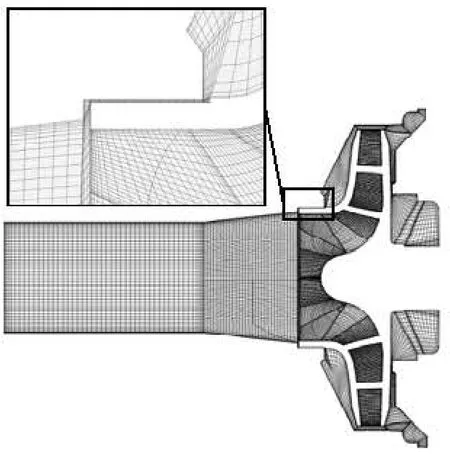
Fig.2 Grid details in impeller and side chamber
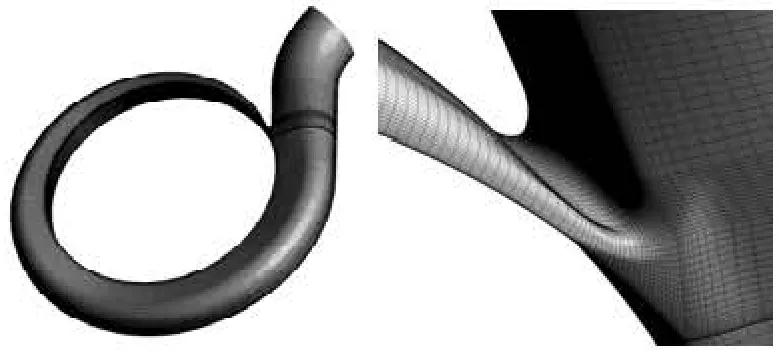
Fig.3 Grid in volute domain
The discretization in space is of second-order accuracy, and the second-order backward Euler scheme is chosen for the time discretization. The interface between the impeller and the casing is set to the “transient rotor-stator” to capture the transient rotor-stator interaction in the flow, because the relative position between the impeller and the casing is different for different time steps with this kind of interface. Two different coordinate systems are utilized for rotation and stationary domains, respectively. The inlet boundary condition is set to the total pressure in the stationary frame while the outlet condition is set to the Mass flow rate, and all specific values are obtained from the laboratory test. The smooth wall condition is used for the near wall function. The chosen time step Δt for the transient simulation is 0.000172414 s for the nominal rotating speed, corresponding to the changed angle of 3o, therefore, 120 transient results are included for one impeller revolution calculation. Within each time step, the number of iterations is chosen as 10 and the iteration stops when the RMS residual is less than 10-4. The convergence criterion for the transient problem is that the result reaches its stable periodicity, 5 revolutions of the impeller for each operational condition in this case are involved. To obtain the stable numerical simulation, a steady calculation with the frozen rotor strategy is carried out in advance.
3. Results and discussions
3.1 Experimental validation
To verify the accuracy of the calculation, experimental data are collected for the model pump in the laboratory, and the test rig is shown in Fig.4. The pressure in the inlet and the outlet is measured by the pressure sensor, with a precision of 0.1%. The flow rates are measured by the LWGY-200A turbine flow meter with the measurement error within 0.5%.

Fig.4 Test rig
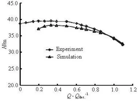
Fig.5 Performance curves for model pump
Figure 5 shows the performance curves for the model pump, and the result under each flow rate is the mean value of the unsteady calculation results. As can be seen from the figure, the measured and the calculated heads are compared for different flow rates. Good agreement is obtained for the design and large flow rates, and the calculated head results are lower thanthe measured ones for part-load conditions, because some additional flow instabilities may occur at small flow rates, and it is not easy to capture them accurately by the URANS CFD simulation.

Fig.6 Time-averaged PFIC distributions in impeller domain at midspan

Fig.7 Time-averaged PFIC distributions around blades at midspan
3.2 Pressure fluctuation intensity analysis under 0.6Qdes.condition
The time-averaged PFIC distribution is shown in Fig.6, which can describe the pressure fluctuation characters for the entire impeller revolution period in the impeller domain. The maximum fluctuation intensity can be found at the blade trailing edge near the blade pressure side for every flow channel under the partload condition. The relative high pressure fluctuation intensity can be clearly observed near the impeller outlet, and the intensity decreases gradually from the outlet to the impeller inlet area, because of a strong rotor-stator interaction at the impeller outlet area. Figure 7 shows the pressure fluctuation intensity distribution around all blades of the impeller at the midspan, and the time-averaged PFIC distributions on both PS and SS of the blade can be clearly seen. The streamline coordinate is defined as 0 at the inlet, 0.25 at the blade leading edge, 0.75 at the trailing edge, and 1.0 at the outlet. The PFIC at LE is smaller than at TE, and a sharp increase of PFIC can be seen at TE, which corresponds to the maximum value described above. From TE to LE, the PFIC decreases slowly around the blade, and the change rate is larger around PS of the blade. The PFIC distribution around PS is larger than SS, and the difference increases from LE to TE. In addition, the PFIC distributions for all blades are almost similar, and the distribution of PFIC is symmetrical in the impeller.

Fig.8 Time-averaged PFIC distributions in side chamber and volute domain
Figure 8 shows the time-averaged PFIC distributions in the side chamber and the volute domain. From the left picture, a high pressure fluctuation can be seen at the area near the blade outlet, which means that in this area a strong fluctuation intensity can be found for three directions. In the right picture, the maximum PFIC can be observed at the beginning section of the spiral not far from the tongue in the volute.
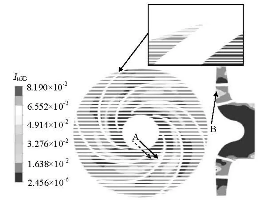
Fig.9 Time-averaged VUIC distributions in impeller domain
3.3 Velocity unsteadiness intensity analysis under 0.6Qdes.condition
Figure 9 shows the time-averaged VUIC distribution in the impeller domain, which can describe the unsteadiness of the flow velocity in the centrifugal pump for entire impeller revolution. In the impeller channel, a high velocity unsteadiness can be clearly seen at position A which is near the blade suction side not far from the blade leading edge, and the unsteadiness spreads to the flow channel toward the outlet direction. In addition, a strong unsteadiness can be seen also at the blade trailing edge near the pressure side. However, in the axial direction, the time-averagedVUIC distributions in the impeller channel are different, a large VUIC can be observed near the blade hub side, as shown at position B.
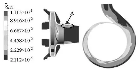
Fig.10 Time-averaged VUIC distributions in side chamber and volute
The time-averaged VUIC distributions in the side chamber and the volute domain under the part-load condition are shown in Fig.10. A strong velocity unsteadiness for an impeller revolution can be found at position A which is strongly influenced by the leakage flow in the pump, although the unsteadiness in the side chamber is not strong. Therefore, the leakage flow has a significant effect on the inflow of the impeller, and can increase the inflow unsteadiness near the wall. In the volute, a strong VUIC can be also found in the area near the volute base line and the tongue, that means that the RSI effects are strong in these areas, which causes the strong velocity variations.

Fig.11 Time-averaged TIC distributions in impeller domain
3.4 Turbulence intensity analysis under 0.6Qdes.condition
Figure 11 shows the time-averaged TIC distribution in the impeller domain under the part-load condition, which can describe the turbulence variation intensity for an impeller revolution. A very strong TIC can be clearly found at position A in the impeller channel near the blade suction side, which takes a half width of the channel. In addition, from the meridian section plane, a strong time-averaged TIC distribution can be observed near the impeller shroud side, shown as position B.
Figure 12 shows the time-averaged TIC distribution in the side chamber and the volute under the partload condition. A strong influence of leakage flow on the inflow turbulence unsteady behaviors can be clearly observed, and the flow with a strong TIC can be seen near the wall, because the unstable flow and the vortexes are caused in this region. An obvious timeaveraged TIC can be also observed in the side chamber, because the flow channel is narrow, and the viscosity of the water becomes an important factor influencing the unsteady flow, and some vortexes with a relatively strong turbulence intensity can be observed in this region.
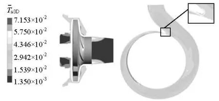
Fig.12 Time-averaged TIC distributions in side chamber and volute
4. Conclusions
Based on the CFD simulation, the 3-D inner flow field in a centrifugal pump with volute is investigated from a brand new angle of view to check some new phenomena of the unsteady flow under a part-load condition in this paper. The whole flow passage is considered in the calculation, and the 3-D periodic flow unsteadiness is quantitatively investigated in detail by defining the time-averaged PFIC, VUIC and TIC, which are calculated by averaging the results of each mesh node for entire impeller revolution period to evaluate the strength distributions of flow unsteadiness directly and comprehensively. The following conclusions are reached from the analysis of the results.
(1) A high pressure fluctuation intensity can be observed near the impeller outlet. The pressure fluctuation intensity is larger near the blade pressure side than near the suction side. A high fluctuation intensity can be also observed at the beginning section of the spiral of the volute.
(2) The flow velocity unsteadiness intensity is stronger near the blade suction side than near the pressure side, and a strong intensity can be observed near the blade hub side.
(3) A strong turbulence intensity can be clearly found near the blade suction side and near the impeller shroud side. An obvious time-averaged turbulence intensity can be observed in the side chamber.
(4) The leakage flow has a significant effect on the inflow of the impeller, and can increase both the flow velocity unsteadiness intensity and the turbule-nce intensity near the wall.
The accumulative flow unsteadiness results of an impeller revolution can be an important aspect to be considered in the centrifugal pump optimum design for obtaining a more stable inner flow of the pump and reducing the flow-induced vibration and noise in certain components.
Acknowledgement
The authors would also like to thank Prof. Feng Jian-jun from Xi’an University of Technology.
[1] GÜLICH J. F.Centrifugal pumps[M]. Heidelberg, Germeny: Springer, 2010.
[2] FENG J., BENRA F.-K. and DOHMEN H. J. Investigation of periodically unsteady flow in a radial pump by CFD simulations and LDV measurements[J].Journalof Turbomachinery,2011, 133(1): 011004.
[3] SHI F., TSUKAMOTO H. Numerical study of pressure fluctuations caused by impeller-diffuser interaction in a diffuser pump stage[J].Journal of Fluids Engineering,2001, 123(3): 466-474.
[4] HE L., CHEN T. and WELLS R. G. et al. Analysis of rotor-rotor and stator-stator interferences in multi-stage turbomachines[J].Journal of Turbomachinery,2002, 124(4): 564-571.
[5] ZHANG M., TSUKAMOTO H. Unsteady hydrodynamic forces due to rotor-stator interaction on a diffuser pump with identical number of vanes on the impeller and diffuser[J].Journal of Fluids Engineering,2005, 127(4): 743-751.
[6] FENG J., BENRA F.-K. and DOHMEN H. J. Unsteady flow visualization at part-load conditions of a radial diffuser pump: by PIV and CFD[J].Journal of Visuali-zation,2009, 12(1): 65-72.
[7] AKHRAS A., HAJEM M E. and MOREL R. et al. Internal flow investigation of a centrifugal pump at the design point[C].Proceedings of 20th IAHR Symposium on Hydraulic Machinery and Systems.Charlotte, NC, USA, 2000.
[8] PINTRAND G., CAIGNAERT G. and BOIS G. et al. Analysis of unsteady flows in a vaned diffuser radial flow pump[C].Proceeding of the XXIst IAHR Symposium on Hydraulic Machinery and Systems.Lausanne, Switzerland, 2002.
[9] SINHA M., KATZ J. Quantitative visualization of the flow in a centrifugal pump with diffuser vanes. part I: On flow structures and turbulence[J].Journal of FluidsEngineering,2000, 122(1): 97-107.
[10] RODRIGUZE C. G., EGUSQUIZA E. and SANTOS I. F. Frequencies in the vibration induced by the rotor stator interaction in a centrifugal pump turbine[J].Journalof Fluids Engineering,2007, 129(11): 1428-1435.
[11] BYSKOV R. K., JACOBSEN C. B. and PEDERSEN N. Flow in a centrifugal pump impeller at design and offdesign conditions-Part II: Large eddy simulations[J].Journal of Fluids Engineering,2003, 125(1): 61-72.
[12] LIU Shu-hong, SHAO Jie and WU Shang-feng et al. Numerical simulation of pressure fluctuation in Kaplan turbine[J].Science China Technological Sciences,2008, 51(8): 1137-1148.
[13] LIU Hou-lin, WANG Kai and KIM Hyoung-Bum et al. Experimental investigation of the unsteady flow in a double-blade centrifugal pump impeller[J].ScienceChina Technological Sciences,2013, 56(4): 812-817.
[14] JIANG Wei, LI Guo-jun and ZHANG Xin-sheng. Effect of oblique angle of blade trailing edge on pressure fluctuation in centrifugal pump[J].Journal of Drainage and Irrigation Machinery Engineering,2013, 31(5): 369-372.
[15] FENG J. Numerical and experimental investigations on rotor-stator interaction in radial diffuser pumps[D]. Doctoral Thesis, Duisburg, Germeny: University of Duisburg-Essen, 2008.
[16] FENG J., BENRA F.-K., DOHMEN H. J. Application of different turbulence models in unsteady flow simulations of a radial diffuser pump[J].Forschung Ingenieu-rwesen,2010, 74(3): 123-133.
[17] FENG J., BENRA F.-K. and DOHMEN H. J. Unsteady flow investigation in rotor-stator interface of a radial diffuser pump[J].Forschung Ingenieurwesen,2010, 74(4): 233-242.
[18] PEI J., YUAN S. and BENRA F.-K. et al. Numerical prediction of unsteady pressure field within the whole flow passage of a radial single-blade pump[J].Journalof Fluids Engineering,2012, 134(10): 101103.
[19] PEI Ji, YUAN Shou-qi and YUAN Jian-ping. Numerical analysis of periodic flow unsteadiness in a singleblade centrifugal pump[J].Science China Technologi-cal Sciences,2013, 56(1): 212-221.
[20] PEI Ji, YUAN Shou-qi and YUAN Jian-ping et al. The influence of the flow rate on periodic flow unsteadiness behaviors in a sewage centrifugal pump[J].Journal of Hydrodynamics,2013, 25(5): 702-709.
10.1016/S1001-6058(14)60029-9
* Project supported by the National Natural Science Foundation of China (Grant Nos. 51239005, 51009072), the National Science and Technology Pillar Program of China (Grant No. 2011BAF14B04).
Biography: PEI Ji (1984-), Male, Ph. D.
猜你喜欢
杂志排行

水动力学研究与进展 B辑的其它文章
- The analysis of second-order sloshing resonance in a 3-D tank*
- Comprehensive analysis on the sediment siltation in the upper reach of the deepwater navigation channel in the Yangtze Estuary*
- Two-phase air-water flows: Scale effects in physical modeling*
- Effect of compressive stress on the dispersion relation of the flexural–gravity waves in a two-layer fluid with a uniform current*
- Capillary effect on the sloshing of a fluid in a rectangular tank submitted to sinusoidal vertical dynamical excitation*
- Improved conservative level set method for free surface flow simulation*