A Numerical Modeling of Failure Mechanism for SiC Particle Reinforced Metal-Metrix Composites
2014-04-17QiubaoOuyangDiZhangXinhaiZhuandZhidongHan
Qiubao Ouyang,Di Zhang,2,Xinhai Zhuand Zhidong Han
1 Introduction
Aluminum Metal Matrix Composites(MMCs)are a class of materials,in which an aluminum alloy is dispersed randomly with SiC particles,and they have become more and more popular due to their light weight,greater strength and stiffness,and are potentially valuable in aerospace and transportation applications.The mechanical behavior of MMCs depends on the characteristics of the reinforced SiC particles,including the particle sizes,shapes and distribution.The design and development of high performance materials requires a thorough understanding and careful control of micro structure and its effect on properties.This is particularly challenging given the multiphase and heterogeneous nature of most high performance composite materials.It is expensive and time-consuming to perform experimental analysis to find the optimized parameters in the composite structures.Analytical and numerical methods have been extensively used in the prediction of mechanical behavior of particle reinforced MMCs.
Analytical techniques have been developed to understand the behavior of particle reinforced composites and they provide an effective means of understanding the deformation mechanism for particle-reinforced MMCs.However,analytical models are unable to accurately predict the properties of particle reinforced composite material,since the simplifications assumed in analytical method make it difficult to study the detailed deformation behavior,and these models do not account for the microstructural factors that influence the mechanical behavior of the material[Chawla and Chawla(2006)]
Due to its simplicity and efficiency,unit cell has long been used in the study of MMCs.Bao et al(1987)used axisymmetric finite element cell models to represent a uniform particle distribution within an elastic-plastic matrix.Schmauder,etc.(2011)used a self-consistent unit cell model to study an Al/TiO2 composites and iterative approach was used to obtain realistic stress–strain curve.They considered the maximum shear stress criterion for the metal phase and the maximum principal stress for the ceramic phase.In general,when the particle fraction is less than 0.2,the simple unit-cell method shows reasonable accurate results for the elastic response.At higher particle fraction,this method will become less accurate[Chawla and Shen(2001)]
While these methods have shed valuable insight into the deformation behavior,they also simplify the heterogeneous microstructure of the composites.These simplifications make modeling and analysis more ef fi cient and straightforward.Nevertheless,it is well known that microstructural complexities,such as the inhomogeneous spatial distribution of particles,irregular morphology of the particles,significantly affect deformation behavior.Thus,while conventional models can provide general knowledge of damage,they are unable to accurately predict the detailed deformation.
The above mentioned researches were based on hypothetical microstructures.Actual microstructures,from optical or scanning electron microscopy(SEM)can be used as direct input to the numerical analysis.Recently,Su et al(2014)used statistic method and studied the effect of the randomly distributed reinforced SiC particles,and they systematically studied the effect of particle size,shapes,position and the volume fractions on the fi nal macro-mechanical behavior.They also considered interface failure between the particle and matrix by using adhesion interface,cohesive interface,and friction interface,respectively.In their study,they found that with the use of adhesion interface,they can predict very accurate Young’s modulus,but overestimate the stress in plastic region;with the use of cohesive interface,they can provide more reasonable prediction of stress in plastic region,but under predict the Young’s modulus.
While the previous studies in this field have made significant advancement in predicting the mechanical properties of particle reinforced MMCs,seldom do they pay enough attention to the different failure mechanisms and their interactions in the deformation process.
In the present paper,a systematic study is carried out to investigate the failure mechanism during the deformation of SiC particle reinforced MMCs,by using the newly developed MLPG-Eshelby Method[Han and Atluri(2014a,b)].Unlike FEM method,in which the deformable part will be represented with many finite elements,in this new algorithm,the whole deformable part will be represented with many small sphere elements,and neighboring sphere elements are connected with bondings.The strength of the bonding depends on the material property of two sphere elements.This algorithm has been implemented into LS-DYNA®,which is used in this study.Four different failure mechanisms were employed to predict the mechanical behavior of the corresponding MMCs with different volume fraction ratios.It is found that interfacial failure between the SiC particle and the aluminum matrix is critical to the deformation of both low and high volume fraction,and the fracture of the SIC particle and the separation of neighboring hard particles are more important for high volume fraction.
2 MLPG-Eshelby Method
2.1 Energy Conservation Laws
The MLPG-Eshelby method is based on the meshless local weak-forms of the Noether/Eshelby Energy Conservation Laws.With the MLPG-Eshelby Method,the satisfaction of the geometric identity for any finite deformation is guaranteed,within a local sub-domain,as

whereXIandxkare the initial and deformed con figurations,respectively.Hence incompatibilities between the shape functions can be eliminated to avoid various locking.The “weighted”momentum balance laws can be introduced based on the energy conservation laws[Han and Atluri(2014a,b)],as

wherePIkis the first Piola-Kirchhoff stress,andFkJis the deformation gradient tensor.For continuous deformations,Eq.(2)is equivalent to the original momentum balance laws,as

For discontinuous deformations,a gap is developed between neighboring sub-domains andFkJis utilized to weight the gap in term of the work done over the gap.Thus,Eq.(2)leads to the energy conversation laws.Eqs(2)&(3)can be applied to any local sub-domains independently.In other words,each local sub-domain may have its own material properties for modeling heterogeneous materials.For more details,we refer the readers to[Han and Atluri(2014a,b)].

Figure 1: Sphere elements represent a composite structure[by Voro++at http://math.lbl.gov/voro++]
In the present study,the 3-dimensional composite structure is discretized into many polydisperse elements,as the non-overlapping sub-domains,instead of the classic finite element mesh.Each polydisperse element is further simplified as one sphere element with the same volume placed at the centroid of volume,as shown in Fig.1.
For heterogeneous MMCs,the polydisperse elements are created to match the statistical distributions of the size,shape,and orientation of the SiC particles,as well as the volume fraction.A typical microstructure obtained from SEM is shown in Fig.2.In order to simulate the strength within one SiC particle,the element size is about one third of the particle size which is fine enough to capture the localized features.A 2-diminsional illustration is given in Fig.3.Comparing to the finite element method,the mesh size usually needs to be one order lower than the particle size in order to capture the stress distribution within the particle[Su et al.(2014)].

Figure 2:A SiC/Al Metal Matrix Composite.
All sphere elements are connected to their neighboring heterogeneous sphere elements The stiffness matrix between all neighboring elements are computed through the weak-forms of Eq.(2)over its neighboring region. The deformation within each element is computed within its neighboring region,and the mechanical behavior of each element is determined by its own material properties,through the LS-Dyna standard material library.Thus,each element is complexly independent from its neighboring particles.

Figure 3:Illustration of discretization of Metal Matrix Composite.

Figure 4:Bonds between elements of Metal Matrix Composite.
In the present study,the stiffness between any two elements is considered as an individual“bond”between these two sphere elements and assembled into the global system matrix.Such bonds are defined between any two elements which are within the influence distance,as shown in Fig.4.There are 4 kinds of bonds defined in the MMCs,i)bonds between two sphere elements of the matrix material A;ii)bonds between one element of the matrix A and another element of the SiC particles B or C;iii)bonds between two sphere elements of one SiC particle,B or C;iv)bonds between two sphere elements of two separated SiC particles.Various combinations form the heterogeneous bonds,as illustrated in 2.2.For“perfectly bonded”elements,the initial stiffness is applied for simulation.Various damage/failure models can be defined for each case independently,and the stiffness may be reduced by a scalar factor once the damage/failure is developed during simulation.In the present study,the energy release rate is used to simulate the initialization,growth and interaction of micro-cracks between elements.
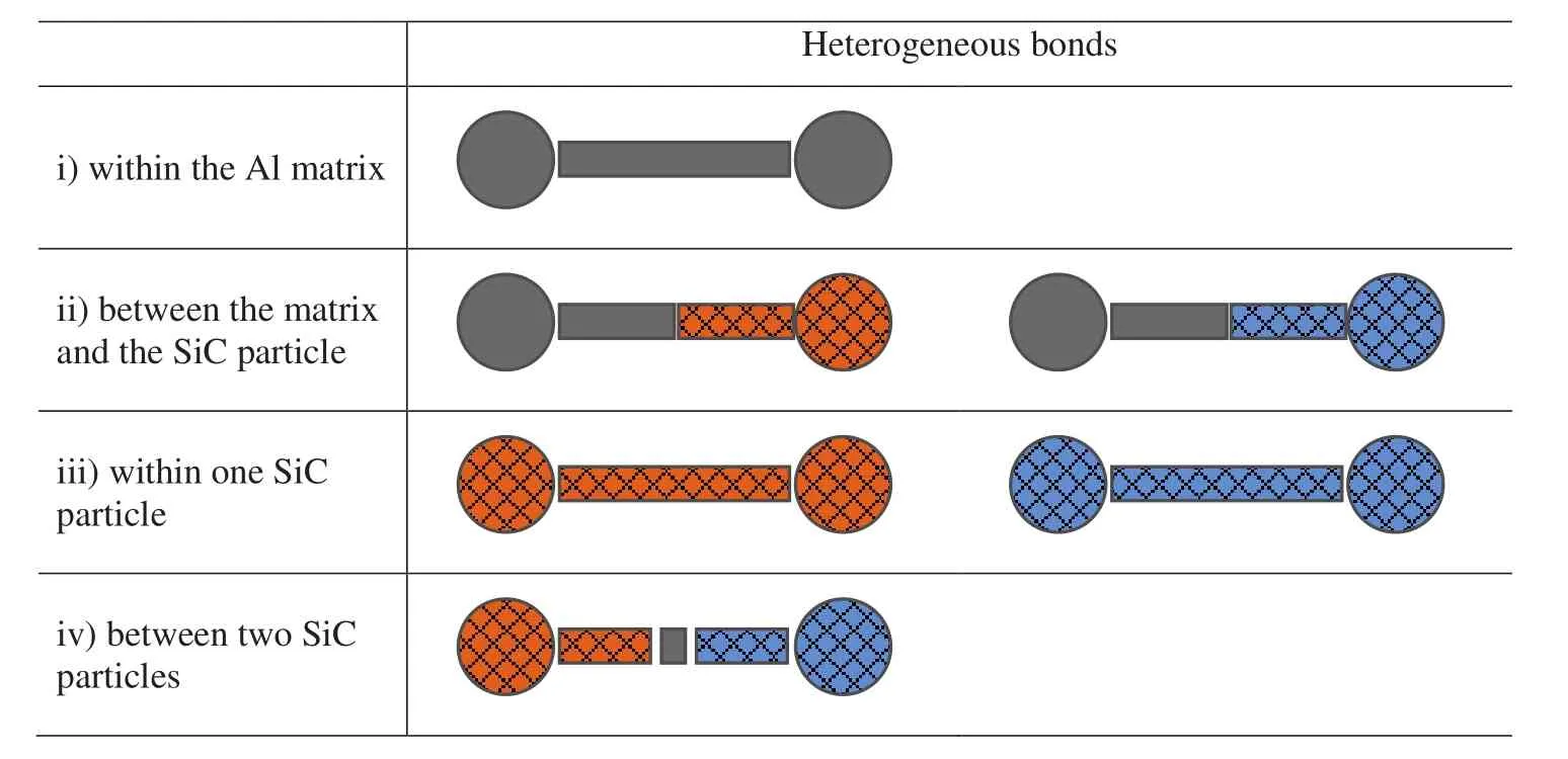
Figure 5:Various bonds between elements of Metal Matrix Composite.

Figure 6:A 3D model of Metal Matrix Composite.
2.2 Comments on the present method
In the computation of mechanical behavior of MMC,the present approach has obvious advantages over the conventional finite element method.When a composite structure is undergone deformation,the deformation is not homogeneous throughout the structure,and the elements along the interface of SiC particles and the aluminum matrix can have significant distortion,which will result in bad aspect ratio or bad mesh quality in some local areas.As a result,the computation accuracy can be negatively affected.However,with the current approach,no element is needed,and the bond stiffness is calculated by two neighboring sphere elements.
Furthermore,the present approach can better deal with material separation or fracture propagation.With conventional finite element method,element deletion is commonly used after the material fails,and it can cause an artificial void inside the structure.In fact,when the material fails in one direction,it can still bear compressive load and still has strength in the other directions.To avoid element deletion,some researches used special interface treatments,such as using cohesive interface or adhesion interface.Those special interfaces have to be pre-defined within a certain region,such as along the SiC particle and aluminum matrix interface.Then the fracture can only grow along the predefined interface and cannot propagate into the matrix or the SiC particle.Accordingly,it will not be able to catch all the detailed failure behavior during the deformation process and the predicted accuracy will be negatively affected.Under the framework of the present approach,if the material fails in some areas,it is easy to break the corresponding bond between two sphere elements,and the propagation of fracture into any direction becomes easier.Accordingly,it is more suitable to study the detailed failure mechanisms during the deformation of SiC particles MMCs.
2.3 Failure Mechanism
When the composite is undergone loading,the load is transferred from the weaker matrix,across the matrix/reinforcement interface,to the hard reinforcement particles.Since the SiC particles are much stronger than the matrix and should have much smaller deformation.Accordingly,the hard particles are bearing more loads and it is the mechanism for the strengthening of the particle reinforced MMCs.With an increase in volume fraction of SiC particles,higher yield stress and tensile strength were observed,coupled with lower ductility.
The initiation and progress of material failure in particle reinforced MMCs subjected to mechanical loading can happen through three basic processes,matrix failure,reinforcement failure and interfacial decohesion.The three failure mechanisms can act independently or interact with other failure mechanisms depending on the strength and stiffness of the matrix and the SiC particles,as well as the shape,distribution and their volume fraction of the SiC particles.Modeling of material failure in MMCs must take into consideration the fracture of the hard particles,debonding of the interface between the hard particle and the aluminum matrix,and the failure of the matrix.Of all of these mechanisms,the interface failure has undergone considerable studies,while the crack of the reinforced hard particle has gained relative less attention.
Matrix-reinforcement decohesion,one of the main damage mechanisms in particlereinforced composites,leads to signi fi cant reductions in strength,ductility.During the deformation,strong strain concentration happens between the interfaces.Interface fracture initiates as the stress exceeds the interfacial strength limit.Then fracture propagates.After the fracture initiates,it can grow along the interface and through the matrix.After the matrix fails,it will result in the final fracture of the materials.
In certain situations,the crack of the SiC particle reinforcement tends to be the primary microscale damage mechanism[LLorca and GonZalez(1998)].When the volume fraction of the SiC particles is high,the spacing between neighboring particles decreases and the deformation concentration becomes more severe.The interactions of neighboring particles cause significant high stress,which can result in the fracture of the hard particles.After the crack of the SiC particles,their capabilities to strengthen the composite decreases and the composites can no longer bear higher strengths.
The fourth failure mechanism,the separation of neighboring SiC particles,can also contribute the final failure of the particle reinforced composites.When two neighboring SiC particles are close to each other,their gap can be very small,for example,they can be less than 1nm and the aluminum will be filled inside the small gap.When conventional FEM method is used,very fine mesh has to be used to model the very thin aluminum within the gap,the element number can be too large and the computation cost can be prohibitively expensive.If the gap between neighboring SiC particles can not be modeled properly,then the two neighboring particles will be considered as one large particle,which will add more constraints to the deformation of the surrounding aluminum matrix.After the neighboring particles separated,they no-longer contribute to load transfer or strengthening.Accordingly,it is important to consider the separation of two neighboring SiC particles.
The onset of any of the above mentioned failure mechanism will result in lower ductility and will play critical role in the mechanical property of particle reinforced MMCs.
With conventional FEA method,if one element fails,the element itself has to be physically removed from the numerical model and forms a void;accordingly,the element can not bear any load in the other directions,which is very unphysical.To model the debonding between the interfaces,some researchers[Segurado and LLorca(2005);Su et al(2014)]used adhesion interface and cohesive interface which allow fracture to grow along the interface.However,with this method,the crack can not grow into the matrix or the SiC particle.As a result,the predicted stresses are higher than the test.
The modeling of the above mentioned failure mechanism becomes easier with the newly implemented MLPG-Eshelby method.Since the model was represented by many sphere elements,and bonds exist be tween neighboring sphere elements.If the deformation between the two neighboring elements is too large,the corresponding bond between them is broken.But it can still bear compressive load,and the bonds with other neighboring elements are still functioning.The above four failure mechanisms can be represented by the break of bonds between different corresponding pair of sphere elements.In the following,the bond failure between each pair is discussed in details.The failure of the matrix can be represented by the break of the bond between two aluminum sphere elements;the failure of the interface between the SiC particles and the aluminum matrix can be represented by the break of the bond between one aluminum sphere element and one SiC sphere element;the crack of the SiC particles can be represented by the bond break between two neighboring SiC sphere elements;and the separation of two sphere particles can be represented by the break of a special bond(bond between two SiC sphere elements).
A simple failure criterion is used in this study:the limit work density.As a bond deforms,it will accumulate certain work.When the work density reaches a limit,then the bond is assumed to fail.Accordingly,the limit work is written as

and the above mentioned four different bonds have their own limit values,denoted as c1,c2,c3,and c4,respectively.
3 Results and Discussions
The aluminum matrix is assumed to be elastic-plastic material with isotropic hardening,and the SiC particles are assumed to be elastic.Detailed information on the material properties can be found from[Su et al.(2014)].
A 3D cubical model of SiC/Al composites was constructed,and the SiC particle is assumed to take the shape of cylinder and randomly distributed over the cubic matrix.The cylinder has length of 13 nm and radius of 5nm.The cubic model has a size of 100 nm for each side.The sphere elements has radius of 2 nm and there are totally 125000 sphere elements in this analysis.
The cubic model is undergone uniaxial tension deformation,and the deformation is not homogeneous inside the MMC structure,then the homogenized stress and strain are obtained.The tensile stress can be calculated by dividing the reaction force with the initial cross section area.The tensile strain can be calculated by dividing the elongation of the cubic with its initial length.
Published material testing data[Su et al.(2014)]are used in this study.There are two different volume fractions of SiC particle reinforced MMCs of 7%and 25%.The baseline parameters are obtained by comparing the prediction with the test data,and the baseline c value for each failure modes are:c1=50MPa,c2=15 MPa,c3=30 MPa and c4=30 MPa.
The ductility of aluminum matrix is critical to the possible elongation of the composites.Fig.7 shows the effect of matrix fracture on the predicted stress-strain curve.In this case,three different values of c1are chosen as,30,50 and 70 MPa,and the other cis are kept constant.Fig.7a)is for volume fraction of 7%and Fig.7b)is for volume fraction of 25%.It is seen that the predicted stress is insensitive to the value of c1before fracture.For the low volume fraction(7%),small value of c1will result in earlier fracture of the composite structure;if c1is large enough,the deformation can continue for an extended strain range even after the peak stress is reached;if c1is too small,the load-bearing capability of the composite is totally controlled by c1.For the case of high volume fraction(25%),it is seen that the other failure mechanisms dominate and c1only has small effect after the peak stress is reached,and the composite quickly reach its fi nal fracture.It is obvious that the ductility of the aluminum matrix has more effect when the volume fraction is low and has little effect when the volume fraction is high.

Figure 7:Effect of matrix failure on the tensile stress.
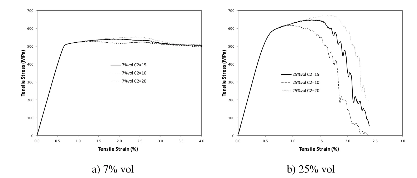
Figure 8:Effect of the interface failure.
Interface failure or debonding has been found to be critical to the mechanical behavior of particle reinforced composites.Fig.8 shows the effect of different failure criterion on the predicted stress-strain curve for SiC volume fraction of 7%and 25%,and in this study three different values of c2are used:10MPa,15MPa and 20MPa.For low SiC particle volume fraction(7%),the effect can be seen from Fig.8a),it is seen that smaller c2causes earlier softening of the composite structure,but the effect is small.It is interesting to note that the stress strain converges after certain deformation(3%).This result can be explained that the strength of the matrix plays the most important role in determining the mechanical behavior of the composite structure after the failure of the interface.For high SiC particle volume fraction(25%)the value of c2has more obvious effect on the predicted stress-strain curve.Smaller value of c2results much lower tensile strength and also earlier fracture,which can be seen from Fig.8b).Unlike for the case of low volume fraction,fracture of the composite structure happens quickly after the peak stress is reached.In the deformation of composite structure,strong stress concentration may happen due to the deformation inhomogeneity,and the stress can be high enough to break the SiC particles.Fig.9 shows the effect of SiC particle failure or fracture of the particle on the mechanical behavior of the composite structure.When the volume fraction is small as shown in Fig.9a),it is seen that the material softening happen earlier for small value of c3,but after stress peaks,there is still obvious relative homogeneous deformation.However,for the case of high volume fraction(25%)as shown in Fig.9b),it is seen that small value of c3results in earlier fracture of the composite structure,and large value of c3can allow the structure to undergo more deformation and later softening.However,after stress peaks,the fracture propagates quickly and result in total fracture of the structure.When the volume fraction is high,the interaction of SiC particles can be significant,which can cause extremely high stress concentration to break the hard particles.For low volume ratio,the interaction of the hard SiC particle is rare,and the deformation is relative homogeneous.So,the stress concentration is not high enough to break the SiC particles.
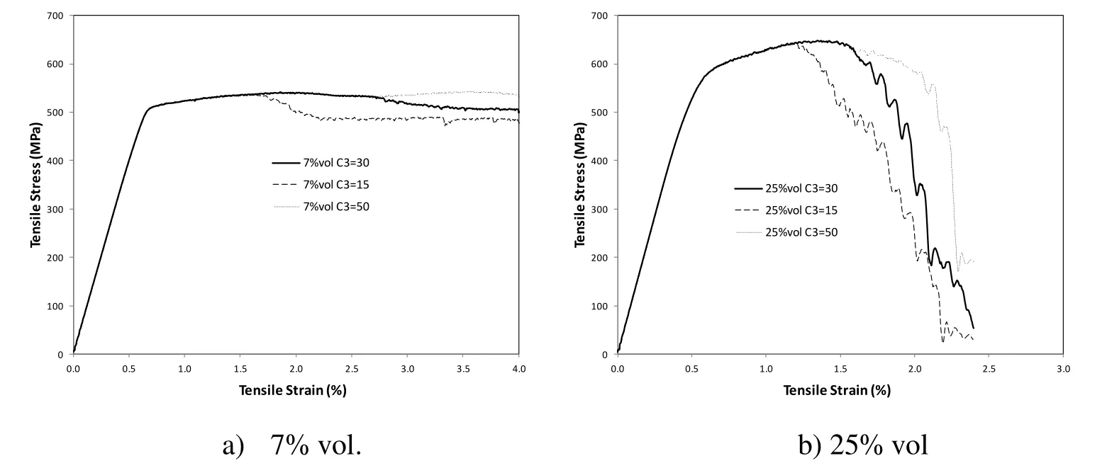
Figure 9:Effect of the crack of SiC particles.
When the gap between two neighboring particles is smaller than the element size,it is impossible to model the effect of particle separation.With the current approach,a new bond which consists of three segments:SiC-Al-SiC,with its own strength and ductility.Fig.10 shows the effect of c4on the mechanical behavior of the composite structure.For low SiC particle volume fraction(7%),there is no effect at all as shown in Fig.10a).For the case of high volume fraction(25%),it is seen that the smaller value of c4allow the structure to fail early,and larger value of c4delay the fracture process.When the SiC volume fraction is small,the gap between neighboring particle might still be big,and there is no such separation of two neighboring SiC particles.However,when the SiC particle volume fraction is high,it is unavoidable that some particles will be close to the other neighboring SiC particles,as shown in Fig.10b).Accordingly,this failure mechanism can affect the mechanical behavior.

Figure 10:Effect of the separation of neighboring SiC particles.
The predicted stress-strain curves are compared with experimental data[Su,et al.(2014)],and was shown in Fig.11.For the case of 7%vol SiC composites shown in Fig.11a),the predicted stress is about 25MPa lower than the experimental in the plastic deformation region,while the predicted stress-strain curve match the test data for 25%vol SiC composites.In quenching process,due to differential thermal contraction between the matrix and the SiC particles,high residual stresses occur during cooling process,which in turn cause hardening effect for the matrix.When the SiC volume ratio is low,the mechanical behavior is more influenced by the matrix.In this study,the hardening effect caused by the thermal stress is not considered,and it is reasonable that lower stress is predicted in the plastic region.For the case of 25%SiC volume ratio,the mechanical behavior is more influenced by the interaction of the SiC particles,and the quenching effect is relatively small,as shown in Fig.11b).
The new method can also better predict the limit strain,defined as the tensile strain corresponding to the peak stress.With adhesion interface or cohesive interface,the predicted stress continue to increase for an extended strain range[Su,et al(2014);Segurado and LLorca(2005)],which is not an observed phenomena from experiment.The current method predicts the peak force followed by obvious material softening,which will eventually result in the total fracture of the structure.
Table 1 shows some the comparisons of some extra material properties between prediction and experimental data.All the predicted Young’s modulus are very close to the test data and the error is within 5%.The predicted tensile strength,which is defined as the maximum stress,are alsoclose to the experimental data.The limit strain,corresponds to the tensile strength,is another important index to evaluate the mechanical property of any composite.After the limit strain,the stress no-longer increase and the failure mechanism dominates.From table 1,it is seen the predicted limit strains are also close to the measure data for all the three SiC particle volume fractions.

Figure 11:Comparisons between the predicted stress-strain curve with test.

Table 1:Mechanical properties of SiC/Al composites.
4 Conclusions
In this study,numerical simulation has been performed for the cubical SiC/Al MMC structure at two volume fraction ratios of 7%and 25%.The SiC particles are represented by sphere cylinders,and are randomly distributed over the whole composite structure.The newly developed MLPG-Eshelby Method was used and four different failure criterions have been considered to better simulate the mechanical behavior of the composite structure.The following conclusions can be drawn:
1.The mesh-free based MLPG-Eshelby Method can be more suitable to simulate the fracture propagations of particle reinforced particle composites.Failure of one bond between two sphere elements only affects the strength in one direction and does not affect the material strength in the other directions.In addition,this method makes it more convenient to model SiC particles with tiny gap between each other.
2.For low volume fraction of SiC particles,the mechanical properties of the aluminum matrix is more important in determining the behavior of compositestructure.
3.The failure between the interface of SiC particle and the aluminum matrix is important for all the cases.
4.For low volume fraction of SiC composite structure,fracture mostly initiates from the interface and propagate into the matrix and results in the total failure of the structure.
5.For high volume fraction of SiC particles,the fracture of the SiC particle,as well as the separation of the neighboring particles also play important roles.Ignoring those failure mechanisms can result in overestimating the predicted stress and limit strain.
6.After considering the four failure mechanisms,the predicted mechanical behavior agree well with experimental data,in both elastic and plastic deformation regions.
This work should provide an important understanding of the material failure mechanism in the deformation of particle reinforced metal matrix composites.
Acknowledgement:The first and second authors acknowledge the financial supports by National Basic Research"973"Program(No.2012CB619600),and National High-Tech R&D"863"Program(No.2013 AA031201).
Reference
Bao,G.;Hutchinson,J.W.;McMeeking,R.M.(1991):Particle Reinforcement of Ductile Matrices Against Plastic Flow and Creep.Acta Metallurgica et Materialia,vol.39,pp.1871-1882.
Chawla,N.;Shen,Y.L.(2001):Mechanical Behavior of Particle Reinforced Metal Matrix Composites.Advanced Engineering Materials,vol.3,No.6,pp.357-370
Chawla,N.;Chawla,K.K.(2006):Micro structure-Based Modeling of the Deformation Behavior of Particle Reinforced Metal Matrix Composites.J.Mater.Sci.vol.41,pp.913-925.
Cordisco,F.A.;Zavattieri,P.D.;Hector,L.G.;Bower,A.F.(2012):Toughness of a patterned interface between two elastically dissimilar solids.Engineering Fracture Mechanics,vol.96,pp.192-208
Dong,M.;Schmauder,S.(1996):Modeling of Metal Matrix Composites by a Self-Consistent Embedded Cell Model.Acta Mater.,vol.44,no.6,pp.2465-2478.
Han,Z.D.;Atluri,S.N.(2014a):Eshelby Stress Tensor T:a Variety of Conservation Laws for T in Finite Deformation Anisotropic Hyperelastic Solid&Defect Mechanics,and the MLPG-Eshelby Method in Computational Finite Deformation Solid Mechanics-Part I.CMES:Computer Modeling in Engineering&Sciences,vol.97,no.1,pp.1-34.
Han,Z.D.;Atluri,S.N.(2014b):On the(Meshless Local Petrov-Galerkin)MLPG-Eshelby Method in Computational Finite Deformation Solid Mechanics–part II.CMES:Computer Modeling in Engineering&Sciences,vol 97,no.3,pp.199-237.
LLorca,J.;Gonzalez,J.(1998):Microstructural factors controlling the strength and ductility of particle reinforced metal-matrix composites.J.Mech.Phys.Sol.,vol 46,pp.1-28.
Qi,Y.;Hector,L.G.(2004):Adhesion and adhesive transfer at aluminum/diamond interface:A first-principles study.Physical Review B.vol.69,2535401
Schmauder,S.;Weber,U.;Reuschel,A.;Willert,M.(2011):Simulation of the Mechanical Behaviour of Metal Matrix Composites.Materials Science Forum,vol.678,pp.49-60.
Segurado,J.;LLorca,J.(2005):A Computational Micro mechanics Study of The Effect of Interface Decohesion on The Mechanical Behavior of Composites.Acta Materialia,vol.53,pp.4931-4942.
Siegel,D.J.;Hector,L.G.;Adams,J.B.(2002):Adhesion atomic structure,and bonding at the AL(111)/α –Al2O3(0001)interface:A first principles study.Physical Review B,vol.65,085415.
Su,Y.S.;Ouyang,Q.B.;Zhang,W.L.;Li,Z.Q.;Guo,Q.;Fan,G.L.;Zhang,D.(2014):Composite Structure Modeling and Mechanical Behavior of Particle Reinforced Metal Matrix Composites.Materials Science&Engineering A,vol.597,pp.359-369