Rupture and Instability of Soft Films due to Moisture Vaporization in Microelectronic Devices
2014-04-16LinsenZhuJiangZhouandXuejunFan
Linsen Zhu,Jiang Zhouand Xuejun Fan
1 Introduction
Three-dimensional(3D)integrated circuit integration has become the mainstream in semiconductor technology with the advantages of small-form factor,high-performance,low power consumption,and high density integration.Wafer-level film lamination is one of the critical assembly steps in 3D integration[ITRS(2014)].A key challenge in the development of high performance microelectronic devices is to meet device reliability performance requirements without material or interface failures[Fan et al.(2008);Fan et al.(2001);Xie et al.(2009)].When soft film is applied,cohesive rupture due to moisture vaporization during soldering re flow process becomes a major concern[Fan,et al.(2006);Huang et al(2006);Prack et al.(2006)].
Moisture plays an important role in the integrity and reliability of microelectronic devices.Many failures in these devices can be traced back to moisture[Fan and Suhir(2010)].When atmospheric moisture is absorbed through microelectronics devices,it condenses in free-volumes or micro-/nano-pores in polymer materials and along interfaces.The condensed moisture will vaporize and produce high vapor pressure during surface mount process,in which the devices and printed circuit boards are entirely placed in a re flow oven.A re flow process is completed within a few minutes,and the peak temperature of devices during re flow typically ranges from 220˚C to 260˚C.Polymer materials,such as dielectric films and adhesive films,become extremely compliant when temperature exceeds their glass transition temperatures.In addition,the inter facial adhesion strength drops substantially.As a result,delamination or cohesive rupture may occur due to the combined effects of thermo-mechanical stresses,hygroscopic stresses,vapor pressure,material softening,and adhesion degradation[Zhang et al.(2006);van Driel et al.(2010)].Extensive studies have been made to investigate the moisture diffusion,desorption,and ensuing mechanical stresses in encapsulated microelectronics devices[Galloway et al.(1997);Kitano et al.(1998);Liu et al.(1995);Tay et al.(1999);Fan et al.(1999)].Specific interests have been focused on the re flow process.The encapsulated moisture,which is absorbed at preconditioning,experiences desorption during re flow.However,significant residual moisture remains inside devices,and moisture vaporates to generate internal vapor pressure inside polymer films.Moisture diffusion and vapor pressure analysis is a key to understand moistureinduced failure mechanism in electronic packaging.Kitano et al.(1998),Tay and Lin(1999)investigated the coupled moisture diffusion and heat transfer in plastic electronic packages.In Tay and Lin’s work,the normalized approach is used for a moisture diffusion analysis.Galloway et al.(1997)characterized moisture properties for different packaging materials and introduced thermal-moisture analogy methodology for moisture diffusion analysis.Wong et al.(1998)introduced an alternative normalized variable,so-called ‘wetness’,which is defined as the ratio of moisture concentration over its saturated moisture concentration.The discontinuity of moisture concentration at interfaces thus can be removed by using those normalized variables.In solving the coupled thermal-moisture-mechanical stress problem-s,the equivalent coefficient of thermal expansion(CTE)method has been used for an integrated stress analysis to consider the combined effects of thermal expansion,hygroscopic swelling,and vapor pressure-induced strains[Tee et al.(2004)].In the equivalent CTE method,a saturated and uniform moisture distribution is assumed for an entire re flow process.However,time-dependent and non-uniform moisture distribution process is not taken into considerations.In addition,the equivalent CTE method cannot be extended to non-linear and time-dependent analysis since it is based on a linear superposition[Fan et al.(2008);Tee et al.(2004)].
In this paper,a damage mechanics-based continuum theory is developed for the coupled analysis of moisture vaporization,moisture absorption and desorption,heat conduction,and mechanical stress.The concept of effective stress is introduced using micromechanics analysis.Void volume fraction and vapor pressure are introduced as two internal field variables.The method is applied to investigate the soft film rupture in a 3-D stacked-die chip scale package subjected to a re flow process.The correlation between the vapor pressure evolution and the film rupture observed from the experiments is established.Further,to understand the mechanism of soft film rupture,a single void growth and instability are studied using neo-Hookean,Mooney-Rivlin,and Ogden’s models,respectively.The instability of the void depends on material property,coefficient of asymmetry,and thickness of the wall.We will discuss whether the collapse of void is due to pressure instability or material strength.
2 Problem Formulation
2.1 Moisture Diffusion
Moisture diffusion behavior is often described by Fick’s law[Crank(1956)]:

where D is diffusivity for moisture diffusion,∇Cthe moisture concentration gradient andis the flux vector=-D∇C.Since the moisture concentrationCis discontinuous at interface of different materials,the"normalized concentration"(often referred to as the"activity"of the diffusing material),is introduced[DeGroot et al.(1962)]

whereSis the solubility of material.When two dissimilar materials are joined at an interface,the normalized concentration φ is continuous across the interface between the two different materials.Equation(1)in terms of the normalized concentration φ becomes

in which the solubility is a function of temperatureT.The above equation is not truly analogous to the original diffusion equation(1)if

On the other hand,a general form of moisture diffusion constitutive model can be written as[Sofronis,P.(1989)]

where κtand κpare temperature and pressure gradient factors,providing diffusion driven by the gradient of temperature and pressure stress,respectively.The pressure p is defined as-σii/3.The temperature gradient driven term in equation(3)can be recovered by equation(5)with

Equation(6)indicates that Equation(3)based on the normalized variable can be considered as a special case of a general type of moisture diffusion by Equation(5).
2.2 Effective Stress and Continuum Theory
Vapor pressure due to moisture is exerted on the solid phase of the material.To describe the coupling phenomena between vapor pressure and matrix material deformation,the effective stress concept is introduced using a micromechanics analysis[Terzaghi(1943)]

where σijis the total stress tensor component,and p,the vapor pressure,andis the effective stress.According to the definition of effective stress,the deformation of porous skeleton is governed by the effective stress only.If a linear,isotropic elastic material is considered,the constitutive model can be described by the effective stress as follows,

whereEand ν are Young’s modulus,and Poisson’s ratio,respectively,and α,β are the coefficients of thermal expansion,and hygroscopic swelling,respectively.∆T=T-T0,T0is a reference temperature,andCis the moisture concentration.By substituting Equation(7)into Equation(8),one obtains

Equation(9)indicates that the vapor pressure contributes to the matrix deformation as an additional volumetric strain term.The total volumetric strain becomes

Equation(9)can be also written as

whereGand λ are Lame’s elastic constants.The deformation equilibrium now becomes

whereuiis the component of displacement vector,eis the total volumetric straine=ui,i,Xiis the component of body force vector.Equation(11)or Equation(12)implies that all applied loads:thermal expansion,hygroscopic swelling and vapor pressure,are in the forms of body loads.The resulting stress/deformation response caused by temperature excursion and moisture diffusion and evaporation can be obtained by solving the force equilibrium equation with the above strain definitions and the governing equations of heat conduction and moisture diffusion.If stress gradient-driven diffusion/heat conduction mechanism can be neglected,the temperature and moisture concentration fields can be determined,prior to a stress analysis,and then they can be incorporated into a subsequent stress analysis.However,vapor pressure in equation(12)must be determined before the stress analysis.Vapor pressure is related to the local moisture concentration and free volume fraction growth,which is coupled with the matrix’s deformation.
2.3 Vapor Pressure Model and Free Volume Fraction Evolution
Although moisture diffusion is analyzed at a macroscopic level,the vapor pressure model should be considered at a microscopic level[Fan et al.(2005)].Moisture exists everywhere in polymer materials,and stays either in the mixed liquid/vapor phase or in the single vapor phase in nano-pores or in free volumes,as shown in Figure 1.Assume that all moisture absorbed is in free(‘unbound’)water liquid or vapor form.Moisture collects at the micro-/nano-pores,in free volumes,at the interfaces,and/or in micro/macro-voids[Fan et al.(2008)].Unbound moisture will evaporate during the re flow process.
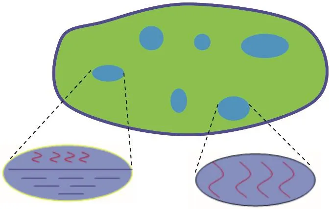
Figure 1:Moisture state in film.
A representative elementary volume(REV)around any considered point in porous medium is considered.The REV is defined in such a way that wherever it is placed within the considered porous medium domain,it always contains both the solid polymer phase and the porous/free volume phase.The total moisture content in a REV is obtained from the local moisture concentrationCat a macroscopic level.If the void volume fractionf(or interstitial space fraction)is known,then the‘apparent’moisture density(ρ)in pores can be defined as[Fan et al.(2008);Fan et al.(2005)]

When the moisture density ρ in pores is less than the saturated water vapor density ρg,the moisture is in the single vapor phase.In this case,since the total moisture content(C*V,where V is REV volume),and the free volume(f*V)are known,the vapor pressure can be obtained using the ideal gas law as follows

hereRis the universal gas constant (=8.314J/(mol·K)),andMMH2Ois the molecular mass of water(=18g/mol).On the other hands,when the moisture density ρ is equal to or greater than the saturated water vapor density ρg,the moisture in pores is in the mixed liquid-vapor phase.Therefore the vapor pressure remains as the saturated vapor pressure,as follows

wherepgis the saturated water vapor pressure.Equations(14)and(15)provide the models to calculate vapor pressure.It indicates that vapor pressure is related to moisture diffusion(moisture concentration C),and temperature field(T),as well as the growth of the void volume fraction f.the void volume fraction may be considered as a damage field variable.The growth of the void must follow the continuity equation,as follows,

which is coupled with the continuum’s deformation in equation(12).
3 Case Study:Application to 3-D Stacked-Die Chip Scale Packages
The above formulations have been implemented in both ABAQUS and ANSYS finite element software with additional user-defined subroutines.As a case study,3-D ultra-thin stacked-die chip scale packages(CSP)are studied in this paper,as shown in Figure 2.The package composes mold compound(MC),multiple silicon dies,multiple die-attach films,solder resist(SR)and BT core.The substrate includes two layers of SR and one layer of BT.The geometry and material property information can be found in[Fan et al.(2006)].In this device,the soft die attach film was used between dies and between the substrate and bottom die.Extensive experimental studies have been conducted to investigate the soft film behaviors during re flow process[Shi et al.(2005)].It has been observed that in some cases,the film rupture occurred consistently.In the following we will present a correlation study with experimental observations.Two scenarios were investigated:the substrate thickness effect and the re flow profile effect.

Figure 2:A case study:stacked-die chip scale package.
3.1 Substrate Thickness Effect
In this case study,Re flow Profile 1,shown in Figure 3,was applied.Re flow profile showed the rapid heating history after the moisture preconditioning.Two substrate thicknesses,200 microns and 280 microns,respectively,are simulated,with all other conditions remaining the same.We focus on the soft film(termed bottom film in Figure 2)behavior between the substrate and the bottom die,since this is where the moisture is absorbed during preconditioning,and released during re flow.Results for both moisture concentration and vapor pressure in film are obtained.Figure 4 shows the contours of moisture concentration at 260°C for packages with different substrate thicknesses.For thinner substrate,moisture concentration in bottom layer film is 54%less than in thicker substrate.It is also observed that there is virtually no difference on moisture concentration in MC and other films.Significant moisture in bottom layer film is lost through substrate during re flow.This indicates that substrate thickness plays a key role in thin package moisture performance.
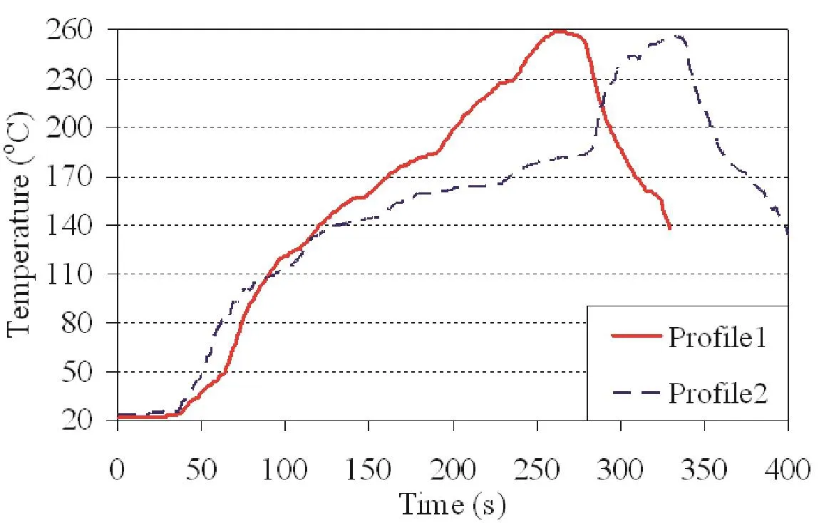
Figure 3:Re flow Profiles.
The contours of vapor pressure are shown in Figure 5 for two substrate thicknesses.For thinner substrate,the vapor pressure is 40%less than in thicker substrate.Figure 6 shows the histories of vapor pressure evolution for these two cases,compared to the saturated vapor pressure as function of temperature.It can be seen that the package with thinner substrate initially has an internal pressure buildup same as the saturated pressure when temperature rises.At certain point,when the moisture is dried out,the pressure starts to fall significantly.On the contrast,for the package with thicker substrate,the release of moisture is not as fast as in the thinner case,significant moisture still retains when the peak temperature is reached.Therefore,the vapor pressure follows the saturated vapor pressure throughout the whole heating process.Experimental results have shown that the failure rate for thicker substrate is significantly higher,while there was virtually no occurrence of the film rupture for thinner substrate[Shi et al.(2010)].
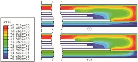
Figure 4:Moisture concentration contours at 260˚C(a).a thinner substrate,and(b).a thicker substrate.
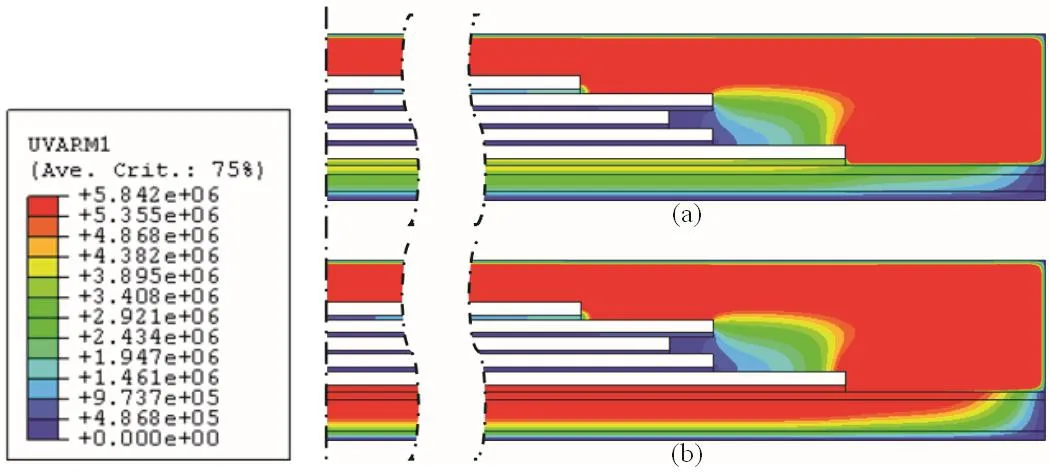
Figure5:Vapor pressure contours at 250˚C(a).a thinner substrate,and(b)a thicker substrate.
3.2 Re flow Profile Effect
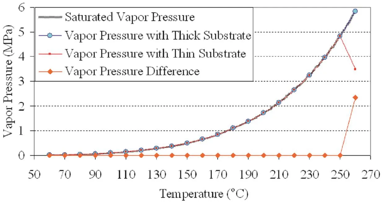
Figure 6:Vapor pressure comparison between two substrate thicknesses.
In this study,two different re flow profiles shown in Figure 3 were applied to the same substrate thickness packages.It can be seen from Figure 3 that Profile 2 has an extended time period(~about 90 seconds)at a temperature level around 180˚C before temperature ramps up rapidly to the peak temperature.This may allow significant moisture release while the vapore pressure below 180˚C is not high enough to cause material rupture.Both profiles eventually reach to a same peak temperature of 260˚C.
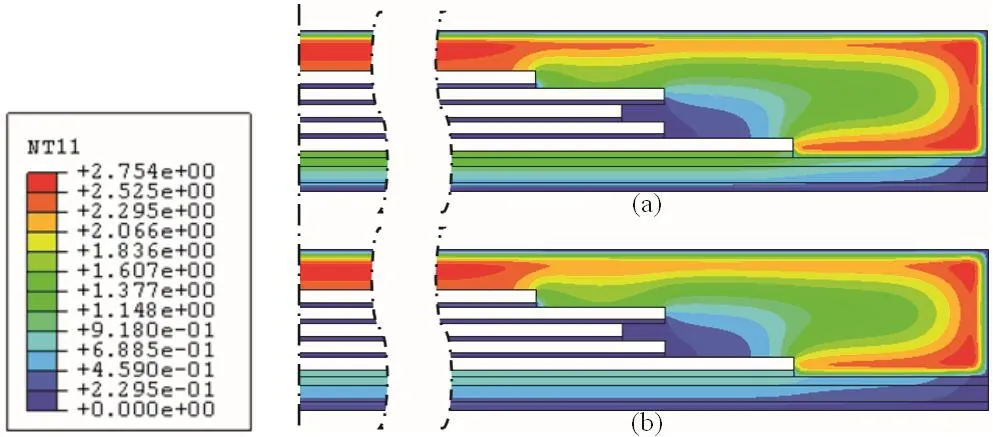
Figure 7:Moisture concentration contours at 250˚C subjected to two different reflow profiles.(a)re flow profile 1;(b)re flow profile 2.
Figure 7 plots the contours of moisture concentration at 250˚C for these two re flow.When Re flow Profile 2 is applied,the moisture concentration in bottom layer film is 34%less than with Re flow Profile 1.This is because Re flow Profile 2 has a longer exposure time at a level of temperature 150˚C to allow more moisture released before it ramps up.Figure 8 plots the vapor pressure evolution in bottom layer film subjected to two re flow profiles.It can be seen that the vapor pressure under Profile 2 starts to fall at a lower pressure than Profile 1.This means that with Re flow Profile 1,a higher vapor pressure will be generated during re flow process,while for Profile 2,since moisture is dried out before the temperature reaches to peak temperature,the pressure drops sharply.Experimental studies have shown that with Profile 2,there was no any failure observed,which are consistent with the simulation results.
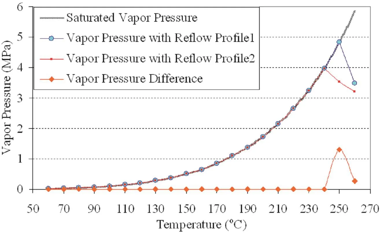
Figure 8:Vapor pressures at the bottom layer film subjected to two re flow profiles.
4 Mechanism Study:Instability of a Spherical Void Subjected to Internal Pressure
Failure analysis of the film has been conducted extensively to understand the mechanism[Shi et al.(2010)].Figure 9 is a cross-section view of the chip-scale package with thick substrate subjected to Re flow Profile 1 with moisture preconditioning.It shows the large-scale cracking and voiding in the bottom film attached to substrate.Other layers of films,which are sandwiched by dies,remain intact.A lapping technique was applied to remove the ruptured film and the images of the ruptured films were taken by scanning electron microscope,as shown in Figure 10.Significant voiding and coarsening in the film was developed.
To understand the film cohesive failure,the instability for general rubbery materials may be applied.Gent(1959)found an initial small void growth in a bulky rubbery material is caused by a hydrostatic tension.A review on cavitation study in rubber is also given by Gent(1990).Ball(1982)described the cavitation as a bifurcation problem.An alternative interpretation for such problems,in terms of the sudden rapid growth of a pre-existing microvoid,has been given by Horgan and Abeyaratne(1992),and Sivaloganathan(1992).Carroll(1987)observed three qualitatively pressure maximum behaviors in inflation of incompressible elastic hollow spheres and stretched cylinders.A balloon inflation experiment was described,and the physical nature of the inflation phenomenon was examined analytically in detail by Beatty(1987).The results for the different materials,rubber,elastomers and biological tissues,were compared.
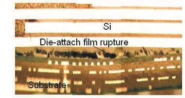
Figure 9:Bottom film rupture during re flow process.
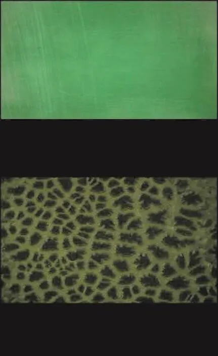
Figure 10:Microstructure of the soft film before and after re flow.
Budianxky,Hutchinson and Slutsky(1982)showed that many defects gradually evolve to spherical voids under large hydrostatic tension.In the present study,a spherical void configuration is considered.The strain energy for a homogeneous,isotropic and incompressible elastic solid material is a function of two invariantsI1,I2

The Cauchy stress tensor σ is given by

In a spherical coordinate system,σris radial stress,and σθand σφare circumferential stress.σθis also known as hoop stress.The stress difference can be written as

If the strain energy function˜W(λ)is defined by

The stress difference can be expressed as

For Mooney-Rivlin strain energy function,it can be expressed as

For Ogden model,

At equilibrium the solutions for Mooney-Rivlin are

where
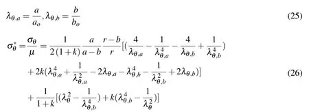
The solutions for Odgen are

And the hoop stress distribution at any location can be derived as

We will use the Equations(24)and(26)for the following analysis.First,let us consider a neo-Hookean model that is the simplest form for the hyperelastic material withC1in Equation(22)related to the shear modulusµbyC1=,andC1=0.Figure 11 plots the general results of the critical normalized pressurep∗(p∗=p/µ)with different thickness ratio of.The peak pressureis defined as cavitation pressure.The corresponding deformation(defined by Equation(25))is known as critical stretch.Figure 11 implies that when the pressure increases to the cavitation,the void will grow unstably,even though pressure starts to decrease.If the applied pressure decreases more than the pressure indicated in Figure 11,the void inflation may halt at certain point.If the pressure continues to increase or even holds as a constant,the void will collapse.As wall thickness increases,the cavitation pressureincreases monotonically.At the extreme case of∗=∞,there is no cavitation pressure exists.However,it can be seen from thep-λθ,acurve that the curve levels off at large stretch.This means that a small increment of pressure can result in large deformation change,which means the void growth become physically unstable.From equation(25),it can be derived that=∞,p∗=2.5.It implies that for any thickness of the wall,there exists an asymptotic value ofp∗,which is 2.5.For example,if the film’s shear modulus is 1 MPa,the maximum cavitation pressure required is less than 2.5 MPa.This value is lower than the internal vapor pressure of 3.0-4.5 MPa generated at 240°-260°C temperature range,as shown in the preceding section.The exact determination of the soft film modulus used is difficult,but the material testing results have shown that the film used has a modulus of 1MPa[25].
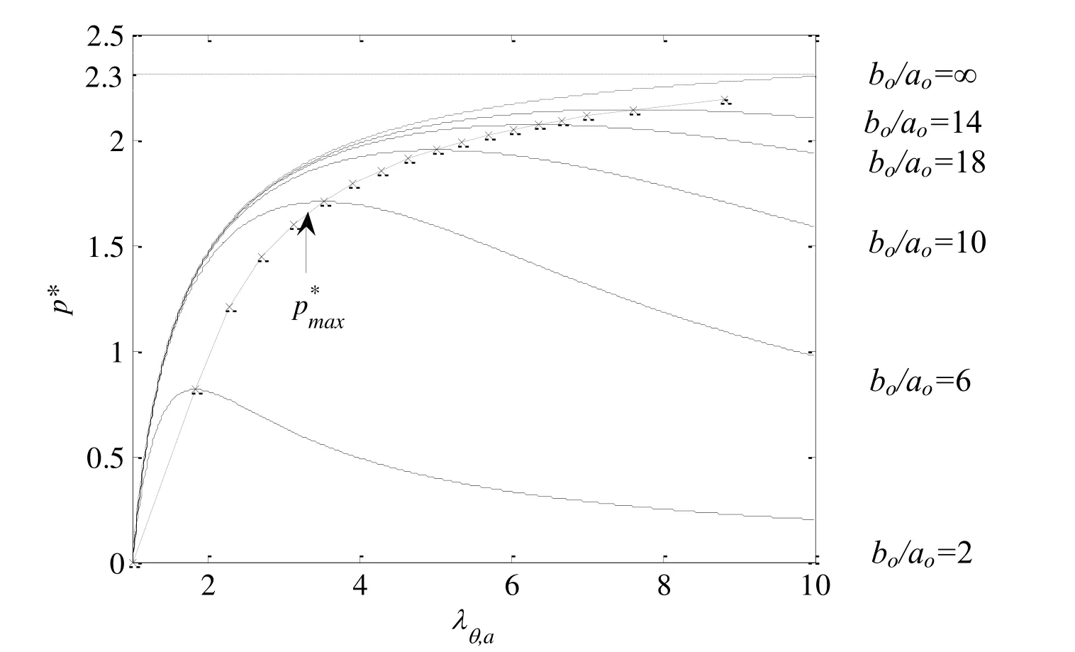
Figure 11:Normalized pressure of a spherical void with neo-Hookean material.
The normalized hoop stresses at inner are shown in Figure 12.The hoop stress increases monotonically despite the fact of the pressure decreases after the cavitation pressure is reached.This implies that as the applied pressure decreases,the overall structure is still under loading condition.Thus,the hoop stress continuously increases.However,if the pressure decreases at a faster rate,the unloading may occur,and the hoop stress may not increase.From this point of view,one may derive two scenarios of failure mechanisms.In the first scenario,after the vapor pressure exceeds the cavitation pressure,and vapor pressure does not drop as fast as required for the unstable growth of the void,the void will burst eventually due to the hoop stress exceeding the material strength.In another scenario,even though the cavitation pressure is reached,it is possible that the void growth will stop when the pressure falls faster.In this case,the hoop stress may not exceed the material strength to cause the material collapse.
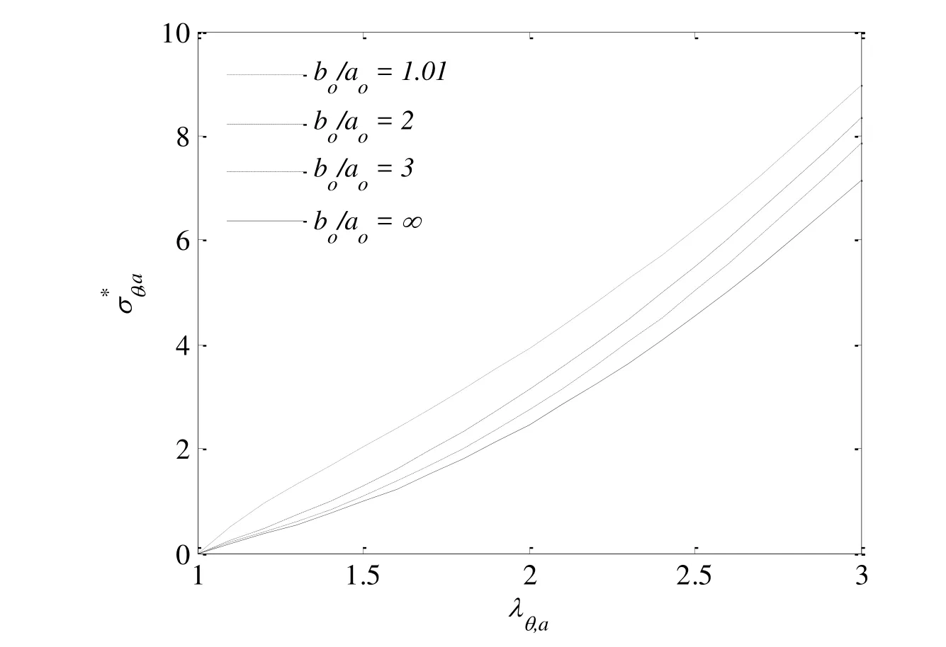
Figure 12:Normalized hoop stress of a spherical void at inner surface with neo-Hookean model.
In the Mooney-Rivlin model,there are two material constantsC1andC2.Therefore,the qualitative behavior of the voids with Mooney-Rivlin model is more complex.The coefficient of asymmetrykrepresents the ratio of two material constantsC2andC1.Figure 13 shows the pressure as function of stretch for different wall thicknesses withk=0.1.The inflation pressure response exhibits both maxima and minima for a smaller thickness.It is seen that the cavitation pressure corresponds to two equilibrium states.The void growth will experience an unstable inflation if the pressure holds as a constant.However,to keep the void grow further,additional load is needed.If the pressure increases again monotonically,the void void will grow stably until collapse occurs.The Mooney-Rivlin model can capture the inflation phenomenon of void more accurately according to the experimental study of Beatty[33].According to the Mooney-Rivlin model,a second stable deformation may be attained after the maximum,instead of a gradual decrease in pressure.For the thicker wall,the cavitation pressure may not exist,but the void growth tends to become physically unstable since the curve in Figure 13 levels off,which means a small pressure increase leads to a large increase in stretch,and eventually will cause the hoop stress to exceed the material strength,as shown in Figure 14.
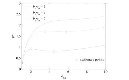
Figure 13:Normalized inflation pressure of a spherical void with differentwith
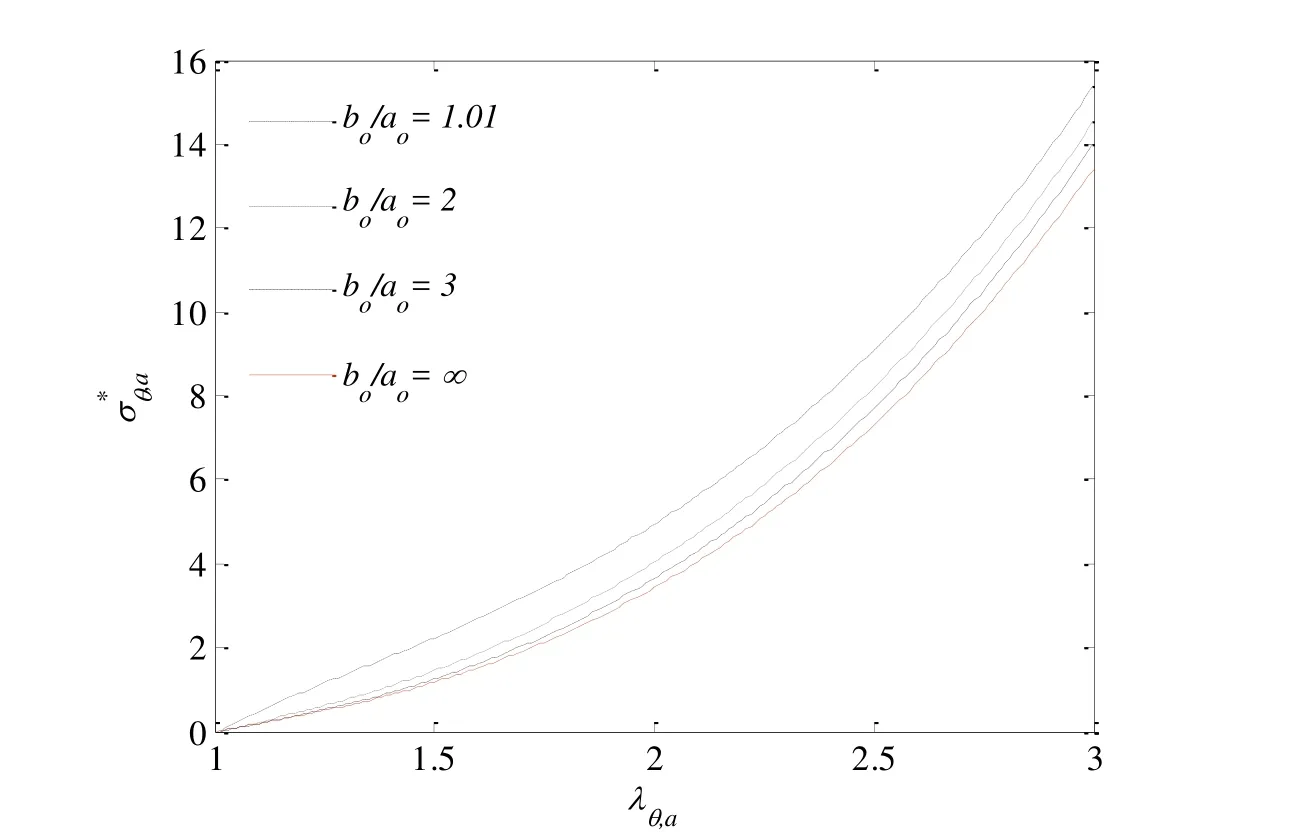
Figure 14:Normalized hoop stress of a spherical void with differentwith
5 Discussions and Concluding Remarks
An important consideration in the selection of materials in microelectronic devices is the cohesive strength of the adhesive film as it relates to the stress in the device induced by mechanical/material/moisture effects.If any of the materials in the device have lower cohesive strength than the stresses imposed during re flow there would be a risk of cohesive failure during re flow.However,the soft materials have to be used in many instances for several purposes:1)compliant material serves as“stress buffer”to relieve the overall stresses in the structure;2)some manufacture process requires compliant materials;and 3)the implementation of soft films can increase the compliance of overall structures.As the device integration continues to go on,the design window for material selection becomes very narrow.The exact mechanics analysis becomes important.
In the present study,a continuum mechanics theory for the multi-field problems in encapsulated microelectronic devices is developed.The effective stress concept is employed to take the moisture vapor pressure into considerations.Vapor pressure model based on a micromechanics analysis provides the relationship between moisture diffusion and void volume growth.A continuum equation is derived for void volume fraction evolution.Both vapor pressure and void volume fraction are introduced as field variables,which are coupled with moisture diffusion,material deformation and heat conduction.Through the case study of the staked-die chip scale packages,the vapor pressure as function of temperature in film is obtained for different substrate thicknesses and different re flow profiles.The correlation between peak vapor pressure and the film rupture has been established,and the results are consistent with the experimental observations.It is found that the vapor pressure initially increases just the same as the saturated vapor pressure when temperature rises.However,at the certain point or temperature vapor pressure may start to fall due to insufficient residual moisture in the film.
Through a single spherical void model analysis,it has been found that the cavitation pressure is at most of the 2.5 times of the shear modulus of film.When cavitation pressure is reached,if the vapor pressure continues to increase,the void will collapse.If the vapor pressure starts to fall,but above the curve predicted in Figures 11 and 13,the void will enter the unstable growth phase,and the rupture will occur.If the vapor pressure falls faster,the unstable void growth will be arrested at the certain point.For Mooney-Rivlin model,since there are two material constants,the qualitative behavior of the voids with Mooney-Rivlin model is more complex.As a result,it is seen that after the cavitation inflation pressure is reached,there exists two equilibrium states that the void will experience an unstable growth.However,the void growth may stop if the pressure does not increase further.In either case,when pressure starts to fall,the hoop stress continues to increase.Eventually it is the hoop stress that exceeds the material strength to cause the collapse of the voids.It is interesting to notice that the strain energy of the void continues to increase even the structure is unloaded during the fall of the pressure,as shown in Figure 15.This implies that the increase of the surface area in voids due to the large deformation will actually increase the total load subjected to the void even though the pressure falls.
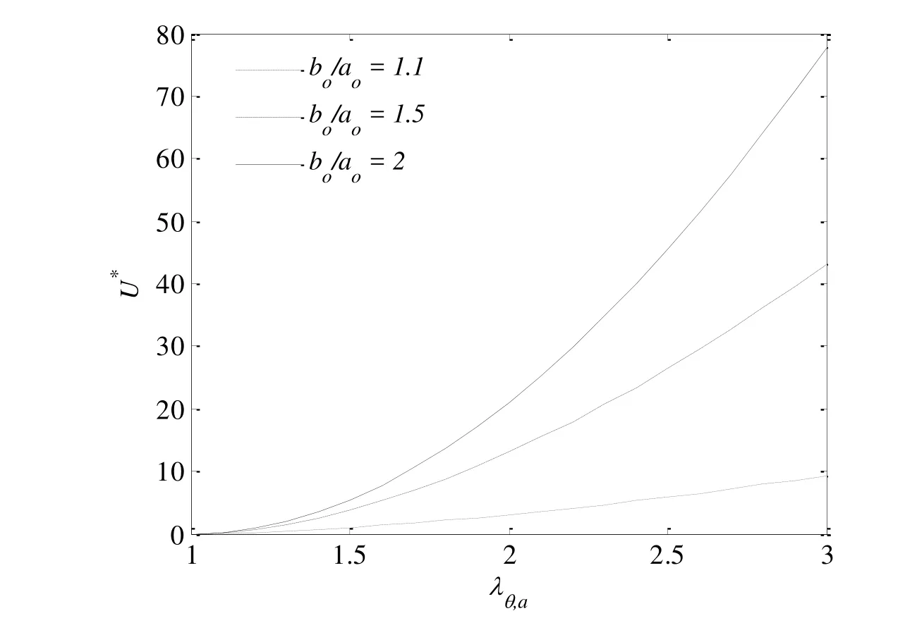
Figure 15:Strain energy of a spherical void with neo-Hookean model.
Wafer level lamination is a new process to replace the traditional adhesive paste process.When adhesive paste is applied,the adhesive modulus is generally greater than 50MPa,therefore the cohesive failure has never been a concern.Instead,the failure always occurs at the interface[Fan et al.(2008)].However,for the film with modulus at high temperature in the range of the saturated vapor pressure(less than 5 MPa at 260˚C),the residual moisture concentration and the peak temperature become the most critical factors to determine the peak pressure.There are several solutions to address moisture-induced soft film rupture problems:1).minimize the substrate thickness and design of the substrate to allow a direct moisture path out of the film;2).change the film to one with higher cohesive strength and relatively lower diffusivity;and 3).adjust the heating profile to allow sufficient time for moisture to escape from the device.
Ball,J.M.(1982):Discontinuous Equilibrium Solutions and Cavitation in Nonlinear Elasticity.Philosophical Transactions of the Royal Society of London,Series A,Mathematical and Physical Sciences(The Royal Society),vol.306,no.1496,pp.557-610.
Beatty,M.F.(1987):Topics in Finite Elasticity:Hyperelasticity of Rubber,Elastomers,and Biological Tissues-with Examples.Applied Mechanics Reviews,vol.40,no.12,pp.1699-1734.
Budianxky,B.;Hutchinson,J.W.;Slutsky,S.(1982):Void growth and collapse in viscous solids.Mechanics of Materials,edited by H.G.Hopkins and M.J.Sewell,Oxford:Permagon Press.
Carroll,M.M.(1987):Pressure Maximum Behaviour in inflation of Incompressible Elastic Hollow Spheres and Cylinders.Quarterly of Applied Mathematics,vol.45,no.1,pp.141-154.
Crank,J.(1956):The Mathematics of Diffusion.Clarendon Press,Oxford.
DeGroot,S.R.;Mazur,P.(1962):Non Equilibrium Thermodynamics.North Holland Publishing Company,North Holland,Amsterdam.
Fan,X.J.;Bekar,I.;Fischer,A.A.;He,Y.;Huang,Z.;Prack,E.(2006):Delamination/cracking root cause mechanisms for ultra-thin stacked die chip scale packages.Intel Conference on Manufacturing Excellence(IMEC),San Diego,CA.
Fan,X.J.;Lim,T.B.(1999):Mechanism analysis for moisture-induced failures in IC packages.Proc of ASME International Mechanical Engineering Congress and Exposition,IMECE/EPE-14.
Fan,X.J.;Suhir,E.(2010):Moisture Sensitivity of Plastic Packages of IC Devices,Springer,New York.
Fan,X.J.;Wang,H.B.;Lim,T.B.(2001):Investigation of the underfill delamination and cracking for flip chip modules under temperature cyclic loading.IEEE Transactions on Components,Manufacturing and Packaging Technologies,vol.24,no.1,pp.84-91.
Fan,X.J.;Zhang,G.Q.;van Driel,W.D.;Ernst,L.J.(2008):Interfacial delamination mechanisms during soldering re flow with moisture preconditioning.IEEE Transactions on Components and Packaging Technologies,vol.31,no.2,pp.252-259.
Fan,X.J.;Zhou,J,;Chandra,A.(2008):Package structural integrity analysis considering moisture;Proc of Electronic Components and Technology Conference(58th ECTC),pp.1054-1066.
Fan,X.J.;Zhou,J.;Zhang,G.Q.;Ernst,L.J.(2005):A micromechanics based vapor pressure model in electronic packages.ASME Journal of Electronic Packaging,vol.127,no.3,pp.262-267.
Galloway,J.E.;Miles,B.M.(1997):Moisture absorption and desorption predictions for plastic ball grid array packages.IEEE Transactions on Components,Packaging and Manufacturing Technology,Part A,vol.20,no.3,pp.274-279.
Gent,A.N.;Lindley,P.N.(1959):Internal Rupture of Bonded Rubber Cylinders in Tension.Proceeding of the Royal Society of London.series A,Mathematical and Physical Sciences.The Royal Society,pp.195-205.
Gent,A.N.(1990):Cavitation in Rubber:A cautionary Tale.Rubber Chemistry and Technology.vol.63,no.3,pp.49-53.
Horgan,C.O.(1992):Void Nucleation and Growth for Compressible Nonlineraly Elastic Materials:An Example.International journal of Solids and Structure,vol.29,pp.279-291.
Huang,Z.;Tang.J.;Hu,C.;Wang,M.;Zhang,M.;Liu,B.;Fan,X.J.;Prack,E.(2006):Moisture induced cohesive delamination in die-attach film in ultra thin stacked chip-scale package.Intel Assembly Test Tech.Journal.
ITRS;(2014):International Technology Roadmap for Semiconductors.http://www.itrs.net.
Kitano,M.;Nishimura,A.;Kawai,S.(1998)Analysis of package cracking during re flow soldering process.Proc.IRPS,pp.90-95.
Liu,S.;Mei,Y.H.(1996):Behavior of delaminated plastic IC packages subjected to encapsulation cooling,moisture absorption,and wave soldering.IEEE Transactions on Components,Packaging,and Manufacturing Technologies,Part A,vol.18,no.3.
Prack,E.;Fan,X.J.(2006):Root cause mechanisms for delamination/cracking in stack-die chip scale packages.IEEE International Symposium on Semiconductor Manufacturing(ISSM),pp.219-222.
Shi,X.Q.;Fan,X.J,;Xie,B.(2010):Moisture sensitivity investigations of 3D stacked-die chip-scale packages(SCSPs),inMoisture Sensitivity of Plastic Packages of IC Devices,Fan XJ and Suhir E(eds),Chapter 18,pp.461-478,Springer,New York.
Shi,X.Q.;Fan,X.J.(2007):Wafer-level film selection for stacked-die chip scale packages.Proc of Electronic Components and Technology Conference(57th ECTC),pp.1731-1736.
Sivaloganathan,J.(1992):Singular Minimizers in the Calculus of Variations:a Degenerate Form of Cavitation.Annales de l’Institut Henri Poincaré(C)Analyse Non Linéairevol.9,pp.657-681.
Sofronis,P.;McMeeking,R.M.(1989):Numerical analysis of hydrogen transport near a blunting crack tip.Journal of the Mechanics and Physics of Solids,vol.37,no.3,pp.317-350.
Tay,A.A.O.;Lin,T.Y.(1999):influence of temperature,humidity and defect location on delamination in plastics packages.IEEE Transactions on Components,Packaging and Manufacturing Technologies,Part A,vol.22,no.4,pp.512-518.
Tee,T.Y.;Zhong,Z.W.(2004):Integrated vapor pressure,hygroswelling and thermo-mechanical stress modeling of QFN package during re flow with interfacial fracture mechanics analysis.Microelectronics Reliability,vol.44,no.1,pp.105-114.
Terzaghi,K.(1943):Theoretical Soil Mechanics.New York:Thio Wiley.
van Driel,W.D.;van Gils,M.A.J.;Fan,X.J.;Zhang,G.Q.;Ernst,L.J.(2008):Driving mechanisms of delamination related reliability problems in exposed pad packages.IEEE Transactions on Components and Packaging Technologies,vol.31,no.2,pp.260-268.
Wong,E.H.;Teo,Y.C.;Lim,T.B.(1998)Moisture diffusion and vapor pressure modeling of IC packaging.Proc.of 48th Electronic Components and Technology Conference,pp.1372-1378.
Xie,B.;Fan,X.J.;Shi,X.Q.;Ding,H.(2009)Direct concentration approach of moisture diffusion and whole field vapor pressure modeling for re flow process:part II-application to 3-D ultra-thin stacked-die chip scale packages,ASME Journal of Electronic Packaging,vol.131,no.3,031011.
Zhang,G.Q.;van Driel,W.D.;Fan.X.J.(2006):Mechanics of Microelectronics,Springer,2006.
