Rapid Regeneration of Chelated Iron Desulfurization Solution Using Electrochemical Reactor with Rotating Cylindrical Electrodes*
2014-03-25于永刘有智祁贵生
(于永)(刘有智)**(祁贵生)
Research Center of Shanxi Province for High Gravity Chemical Engineering and Technology, North University of China, Taiyuan 030051, China
Rapid Regeneration of Chelated Iron Desulfurization Solution Using Electrochemical Reactor with Rotating Cylindrical Electrodes*
YU Yong(于永), LIU Youzhi(刘有智)**and QI Guisheng(祁贵生)
Research Center of Shanxi Province for High Gravity Chemical Engineering and Technology, North University of China, Taiyuan 030051, China
A new electrochemical reactor with rotating cylindrical electrodes was designed and used to increase the regeneration efficiency of chelated iron desulfurization solution. The influence of operating parameters, such as the rotation speed of electrode, voltage, and inlet air and liquid flow rates, on the regeneration rate was investigated. Compared with the traditional tank-type reactor, the regeneration rate with the new electrochemical reactor was increased significantly. Under the optimum conditions, the regeneration rate was increased from 45.3% to 84.8%. Experimental results of continuous operation indicated that the new electrochemical regeneration method had some merits including higher regeneration efficiency, smaller equipment size and good stability in operation.
regeneration, desulfurization, chelated iron, electrochemistry, reactor
1 INTRODUCTION
H2S is a toxic, malodorous and sour gas emitted from industrial activities such as petroleum refining, pulp and paper manufacturing, food processing, natural gas treating and coal gasification, which leads to severe air pollution and results in great harm to people’s living and production. The removal of H2S has become a very important gas cleanup process in the chemical industry. Several desulfurization methods, such as dry-, semidry- and wet-processes, have been proposed. The wet desulfurization method is the main technology used [1] due to larger treatment volume, easier recovery of sulfur and more stable operation. Many wet desulfurization methods have been developed, such as the rectisol method, methyldiethanolamine (MDEA) method, polyethylene glycol dimethyl ether (NHD) method, Stretford method, chelated iron method and binuclear cobalt phthalocyanine ammonium sulfonate (PDS) method, among which the chelated iron method is more widely applied abroad [2-6], and its representative technologies are the liquid oxidation catalyst (LO-CAT) process and the SulFerox process [7-9]. While the chelated iron method is still on a laboratory scale in China, there are few reports in industrial applications.
H2S-removal by the chelated iron method is generally considered as a fast, safe, green and economical method with the advantages of non-toxic reagent with negligible losses. The chelated iron desulfurization processes have been proved to be economically advantageous over other options for throughputs between approximately 250 and 2.0×10⁴kg of sulfur per day [10]. The chemical absorption of H2S with chelated iron is usually represented by Eqs. (1)-(3) [11].

Where n denotes the charge of an organic ligand L. Since the active chelated iron is converted into inactive chelated iron, the latter component has to be regenerated into its ferric form by oxidation of the solution with oxygen. The regeneration reaction is usually represented by Eqs. (4) and (5) [11].

Judging from the viewpoint of reaction dynamics, Eqs. (3) and (5) are very rapid, while Eqs. (1) and (4) are relatively slow and are the rate controlling steps in all chelated iron processes [12]. The control step of absorption process is the gas film mass transfer [13-15], which can be greatly enhanced by the new chemical absorption method or equipment with process intensification [16-18]. However, the regeneration process of the chelated iron method is the key step mainly because the solubility of oxygen is extremely low in the liquid phase, which results in slower regeneration speed and lower regeneration efficiency. The traditional regeneration process is generally carried out in a packed column, spray tank or spray tower [19, 20], which has many demerits, such as poor mass transfer efficiency, larger equipment volume, lower regeneration efficiency and higher energy consumption. Therefore, researches have been focused on developing good regenerative processes and equipment featuring fast regeneration speed and high regeneration efficiency, which will have great significance on decreasing theliquid circulation and operating costs.
In recent years, electrochemical methods have gained increasing interest thanks to their high efficiency, compact facilities, low operating costs and friendly environment, which are studied individually by electrooxidation process, (EOP) [21], electro-coagulation process, (ECP) [22] and electro-Fenton process, (EFP) [23]. The electro-oxidation process is widely applied to the treatment of synthetic solutions containing phenolic compounds [24, 25] and real wastewater, such as textile effluents [26, 27], landfill leachate [28], olive oil wastewaters [29], domestic sewage [30] and tannery waste liquors [31, 32]. The equilibrium potential of the chelated iron desulfurization solution in experiments is relatively low, the reducibility of which is strong. The powerful oxidation of the electro-oxidation process is used to enhance the regeneration effect of the chelated iron desulfurization solution. Meanwhile, this study combines the air oxidation method with the electrooxidation process to intensify the rapid regeneration of the desulfurization solution. In this work, a new electrochemical reactor with rotating cylindrical electrodes is designed and used to increase the regeneration efficiency of the chelated iron desulfurization solution. The new regeneration technology will provide theoretical and experimental basis for industrial applications. This paper focuses on the regeneration process only.
2 EXPERIMENTAL
2.1 Materials and methods
The air used in experiments was from an air steel container. The chelated iron desulfurization solution was collected from a chemical plant, which had an initial pH value of 8.52, an initial temperature of (21±1) °C, an equilibrium potential of −127 mV, a Fe3+Ln−concentration of 0.016 mol·L−1and a Fe2+Ln−concentration of 0.046 mol·L−1. A kind of phenol catalyst was added to the chelated iron desulfurization solution to improve the regeneration efficiency. The concentrations of Fe2+Ln−and Fe3+Ln−were analyzed with potassium dichromate method. The pH value and equilibrium potential of solution were measured with digital pH meter (Model PHS-3C). An electrical voltage was supplied by a direct current (DC) power supply (Model SPWM- 3030). The rotational speed of electrode was measured by a measuring instrument (Model TESTO-471). The regeneration rate η is applied to characterize the regeneration efficiency of chelated iron desulfurization solution, which is defined as: η= (cin−cout)/cin×100%, in which cinand coutare the Fe2+Ln−concentrations in the inlet and outlet of the electrochemical regeneration device (mol·L−1), respectively.
2.2 Experimental setup and process flow diagram

Figure 1 Structure diagram of electrode1—fixed position of electrode and axis; 2—hole; 3—mesh electrode
Figure 1 shows the structure diagram of electrode. The shape of the electrode is a cylinder, which is fixed on the rotating shaft through the upper and lower fixed points. Two mesh electrodes are placed in the cylinder to strengthen the gas-liquid mass transfer process and electrochemical reactions. Twelve circular holes are designed in the wall of the cylinder in four directions to intensify the interphase mass transfer. The cylindrical electrode has a diameter of 200 mm and a height of 300 mm. The diameter of circular hole in the wall is 60 mm. The mesh electrode in the cylinder is regularly arranged in square-like. The structure of the anode and cathode is the same. The anode material is made of the titanium-based compound material and the cathode material is made of the stainless steel.
Figure 2 shows the flow chart for the new electrochemical reactor system for regeneration process. Several gas distributors like mushrooms are placed at the bottom of the anode cylinder regularly. Many tiny air holes are punched on the head of each mushroom. Liquid distributors are installed above the anode cylinder and cathode cylinder. The shape of the whole electrochemical reactor is a cuboid. The anode chamber is the same size as the cathode chamber, which has a length of 300 mm, a width of 300 mm and a height of 500 mm. The catholyte is the sodium chloride solution (concentration of 2.0 mol·L−1). The anolyte is the chelated iron desulfurization solution. The height of liquid level is maintained in about 350 mm in the anode chamber and cathode chamber in experiments.
In the experiments, the chelated iron desulfurization solution was pumped from the storage tank to the inner of the anode cylinder via a liquid distributor, which moved downward via a gravity force. The air was dispersed to the tiny bubbles via a gas distributor, which moved upward via a buoyant force. Both gas and liquid streams contacted counter-currently in the anode chamber, in which the chelated iron desulfurization solution was regenerated by air under rapid stirring of the rotating electrodes. Meanwhile, the rotating electrodes could provide a large and quickly updated surface to accelerate the regeneration process of electrochemical oxidation.
3 RESULTS AND DISCUSSION
3.1 Effect of rotation speed of electrode on the regeneration rate
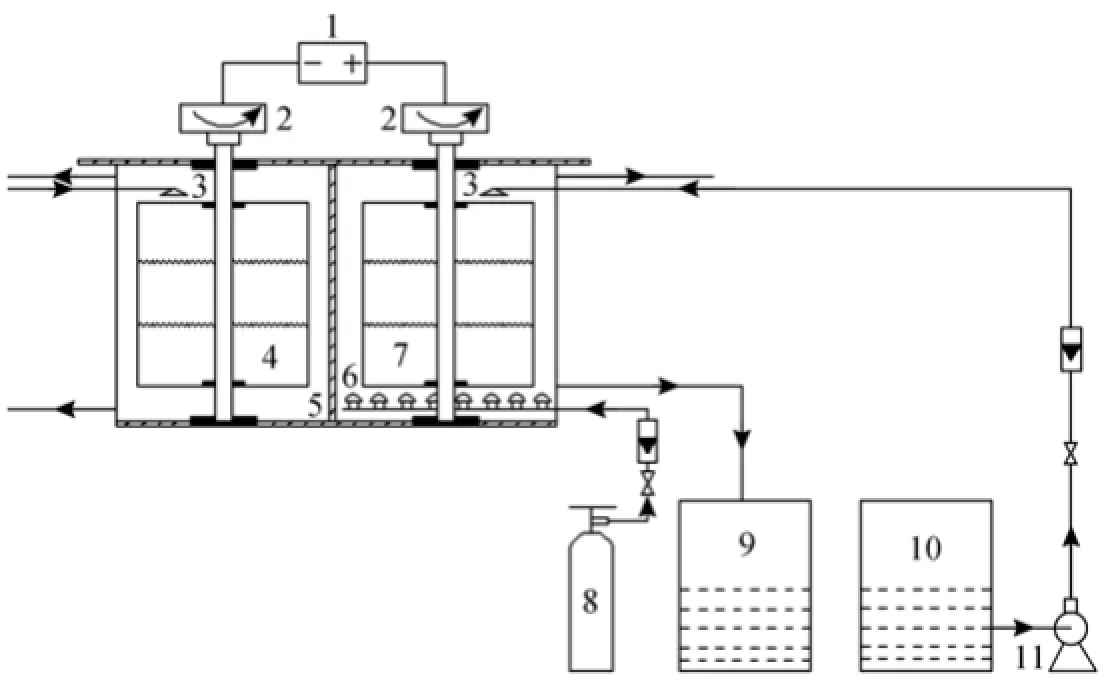
Figure 2 Experimental process flow diagram1—power supply; 2—motor; 3—liquid distributor; 4—cathode; 5—ceramic membrane; 6—gas distributor; 7—anode; 8—air steel container; 9—regenerated solution tank; 10—original desulfurization solution tank; 11—pump

Figure 3 Effect of rotation speed of electrode on the regeneration rate
Figure 3 illustrates the effect of rotation speed of electrode on the regeneration rate at a voltage of 4 V, an inlet air flow rate of 2 m3·h−1and an inlet liquid flow rate of 80 L·h−1. A higher rotating speed of electrode is favorable to increase the regeneration rate, resulting in higher regeneration efficiency. At lower rotating speed, the air bubbles in solution and the bubbles created during electrochemical reactions can adhere easily to the electrode surface and reduce the electrode activity area, which will decrease the electrochemical oxidation efficiency. With an increasing rotating speed, the bubbles can be timely detached from the electrode surface, and the thickness of diffusion layer decreases and the concentration difference can be eliminated rapidly. The increase of current density enhances the electrochemical regeneration effect. At the same time, the gas-liquid mixing degree and turbulence intensity will be enhanced to favor the mass transfer at a higher rotating speed, which can lead to the quick supplement of the dissolved oxygen consumed in the regeneration process. Thus, the regeneration rate increases with increasing rotating speed. However, when the rotating speed of electrode is too high, the contact time between the chelated iron solution and electrode is shortened, and the electrochemical oxidation reactions will be not complete, so the regeneration rate decreases slightly. Moreover, it is well known that higher rotating speed will cause higher energy consumption, which must be considered in industrial applications. In this experiment, the regeneration rate can reach a maximum value of 84.9% when rotation speed of electrode is equal to 180 r·min−1, which is about 1.6 times that achieves in the static electrode environment. The experiments demonstrate that the rotating electrode has significant advantages in improving the regeneration rate.
3.2 Effect of voltage on the regeneration rate
Figure 4 shows the influence of voltage on the regeneration rate at a rotation speed of electrode of 180 r·min−1, an inlet air flow rate of 2 m3·h−1and an inlet liquid flow rate of 80 L·h−1. The regeneration rate increases as voltage increases due to that the current density increases rapidly at the initial stage with the increase of voltage, resulting in an increased electrochemical reaction driving force. The increase of voltage is favorable to the regeneration rate in both of the rotating electrode and the static electrode environments. But the regeneration rate in the rotating electrode environment is higher than that in the static electrode environment at the same voltage due to that the rotating electrode can provide a great and rapid renewed surface of the electrode to strengthen the electrochemical oxidation process. When the voltage is above 4 V in the rotating electrode environment, the regeneration rate increases slowly probably due to that the current density and the electrochemical reaction driving force increases slowly. Moreover, too high voltage easily leads to higher energy consumption and more side reactions. Thus, an appropriate voltage of 4 V is selected and the regeneration rate is 84.8%. The new electrochemical reactor can be considered as thetraditional tank-type reactor on condition that the voltage is 0 V in the static electrode environment. Under the optimum conditions, the regeneration rate of the new electrochemical reactor is increased from 45.3% to 84.8% compared with the traditional tank-type reactor. The experiments indicate that the rotating electrode can dramatically improve the efficiency of electrochemical oxidation.

Figure 4 Effect of voltage on the regeneration rate■ rotating electrode; ▲ static electrode
3.3 Effect of inlet air flow rate on the regeneration rate

Figure 5 Effect of inlet air flow rate on the regeneration rate■ rotating electrode; ▲ static electrode
Figure 5 shows the effect of inlet air flow rate on the regeneration rate at a rotation speed of electrode of 180 r·min−1, a voltage of 4 V and an inlet liquid flow rate of 80 L·h−1. With increasing inlet air flow rate, the regeneration rate first increases rapidly and then changes slightly both in the rotating electrode and static electrode environments due to that the dissolved oxygen accelerates the regeneration reactions. But in the rotating electrode environment, the regeneration rate is always higher than that achieved in the static electrode environment because the rotating electrode strengthens the micro-mixing efficiency of the air and solution, resulting in excellent mixing and higher mass transfer rate. When inlet air flow rate increases to higher than 2 m3·h−1, the regeneration rate increases slowly. The reason may be that the residence time of air becomes shorter in solution and the gas-liquid mass transfer efficiency decreases with a too large inlet air flow rate. Therefore, an inlet air flow rate of 2 m3·h−1is appropriate and the regeneration rate is 84.8%. The experiments indicate that the rotating electrode has significant influence on improving the regeneration efficiency of air oxidation.
3.4 Effect of inlet liquid flow rate on the regeneration rate
Figure 6 illustrates the effect of inlet liquid flow rate on the regeneration rate at a rotation speed of electrode of 180 r·min−1, a voltage of 4 V and an inlet air flow rate of 2 m3·h−1. The regeneration rate first decreases slowly and then decreases rapidly with the increase of the inlet liquid flow rate in the rotating electrode environment, which shows the same trend as the case of the static electrode environment. The smaller the inlet liquid flow rate is, the longer the residence time of liquid in the electrochemical reactor will be. Long residence time can benefit the regeneration of the chelated iron desulfurization solution because the gas-liquid contract time and the electrolysis time are one of the most important influence factors of the regeneration process. When inlet liquid flow rate is less than 80 L·h−1, the regeneration rate remains at over 84.6%. When inlet liquid flow rate continues to increase to higher than 80 L·h−1, the residence time of liquid in the electrochemical reactor becomes shorter gradually, resulting in rapid decrease in the regeneration rate. Under the condition that the treatment capacity is bigger and the regeneration rate is higher, an optimum inlet liquid flow rate of 80 L·h−1is selected and the regeneration rate reaches 84.6%, which is about 1.6 times that in the static electrode environment. Theexperiments demonstrate that the rotating electrode has significant advantages in increasing the treatment capacity of regeneration process.

Figure 6 Effect of inlet liquid flow rate on the regeneration rate■ rotating electrode; ▲ static electrode
4 CONCLUSIONS
A new type of electrochemical reactor with rotating cylindrical electrodes exhibits better regeneration performance for the chelated iron desulfurization solution than the traditional tank-type reactor due to its good electrochemical oxidation property and gas-liquid mass transfer performance. The novel electrochemical reactor can not only provide a great and rapid renewed surface to accelerate the regeneration process of electrochemical oxidation, but also provide an excellent gas-liquid mixing environment to strengthen the regeneration process of air oxidation, overcoming the poor mass transfer effect and the low oxidation regeneration efficiency in the traditional tank-type reactor. Under the optimum conditions, the regeneration rate of chelated iron desulfurization solution is increased from 45.3% to 84.8%. Such a new electrochemical reactor offers an opportunity for high-efficiency and continuous operation for regeneration of chelated iron desulfurization solution, which may reduce the liquid circulation, shrink the equipment size and decrease the energy consumption. Moreover, the combination of the novel electrochemical regeneration method and the high gravity chelated iron desulfurization technology will have some advantages, such as higher sulfur capacity, higher desulfurization efficiency, higher regeneration efficiency and smaller equipment size, which will potentially have a great market for industrial applications.
REFERENCES
1 Liang, F., Xu, B.G., Shi, X.H., Ming, S.R., “Advances in desulfurization with wet oxidation process”, Modern Chem. Ind., 23 (5), 21-24 (2003). (in Chinese)
2 Clarke, E.T., Solouki, T., Russell, D.H., “Transformation of polysulfidic sulfur to elemental sulfur in a chelated iron, hydrogen sulfide oxidation process”, Anal. Chim. Acta., 299 (1), 97-111 (1994).
3 McManus, D., Martell, A.E., “The evolution, chemistry and applications of chelated iron hydrogen sulfide removal and oxidation processes”, J. Mol. Cat. A., 117 (1), 289-297 (1997).
4 Eng, S.J., Motekaitis, R.J., Martell, A.E., “The effect of end-group substitutions and use of a mixed solvent system on β-diketonates and their iron complexes”, Inorg. Chim. Acta., 278 (2), 170-177 (1998).
5 Eng, S.J., Motekaitis, R.J., Martell, A.E., “Degradation of coordinated β-diketonates as iron chelate catalysts during the oxidation of H2S to S8by molecular oxygen”, Inorg. Chim. Acta., 299 (1), 9-15 (2000).
6 Piché, S., Ribeiro, N., Bacaoui, A., “Assessment of a redox alkaline/iron-chelate absorption process for the removal of dilute hydrogen sulfide in air emissions”, Chem. Eng. Sci., 60 (22), 6452-6461 (2005).
7 Dalrymple, D.A., Trofe, T.W., Evans, J.M., “An overview of liquid redox sulfur recovery”, Chem. Eng. Prog., 85 (3), 43-49 (1989).
8 Eaton, R. F., “Update LO-CAT/LO-CAT II process design and applications”, In: Proceedings Sulfur Recovery Conference, Austin GRI, 73-82 (1995).
9 Dostwouder, S.P., “Gas separation membranes coming of age for carbon dioxide removal from natural gas”, In: 45th Annual Lauraceous Reid Gas Conditioning Conference, University of Oklahoma, Norman, 284-307 (1995).
10 Oostwouder, S.P., Hodge, V.B., “SulFerox process technology and application update”, In: GRI Sulfur Recovery Conference, Radian Corporation, Austin, 49-59 (1995).
11 Wubs, H.J., Beenackers, A.A.C.M., “Kinetics of the oxidation of ferrous chelates of EDTA and HEDTA in aqueous solutions”, Ind. Eng. Chem. Res., 32 (11), 2580-2594 (1993).
12 Heguy, D.L., Nagl, G.J., “Consider optimized iron-redox processes to remove sulfur”, Hydrocarbon Processing, 82 (1), 53-57 (2003).
13 Ebrahimi, S., Kleerebezem, R., Loosdrecht, M.C.M., “Kinetics of the reactive absorption of hydrogen sulfide into aqueous ferric sulfate solutions”, Chem. Eng. Sci., 58 (2), 417-427 (2003).
14 Chen, J.F., High Gravity Technology and Application, Chemical Industry Press, Beijing, 163-166 (2003). (in Chinese)
15 Liu, Y.Z., Chemical Engineering Process and Technology in High Gravity, National Defence Industry Press, Beijing, 47-70 (2009). (in Chinese)
16 Guo, F., Li, F.Y., Cao, Z.G., “Research on absorption process technology for high concentration H2S treatment by compounded complex ferric solution”, Refining Chem. Ind., 18 (2), 7-9 (2007). (in Chinese)
17 Qi, G.S., Liu, Y.Z., Jiao, W.Z., “Desulfurization by high gravity technology”, Chem. Ind. Eng. Progr., 27 (9), 1404-1407 (2008). (in Chinese)
18 Cao, H.B., Li, Z.H., Hao, G.J., “Pilot plant experiment for removal of hydrogen sulfide from oil-associated gas by high gravity complex iron method”, Petrochem. Technol., 38 (9), 971-974 (2009). (in Chinese)
19 Jiang, L.F., Gao, C.Z., Wang, Z.H., “Industrial test on sulfur removal by wet method and catalysis of modification chelate iron”, Shandong Chem. Ind., 1, 33-35 (1998). (in Chinese)
20 Yang, J.P., Li, H.T., Xiao J.G., “Study on desulfurization from acidic gaseous stream by chelate iron”, J. Chem. Ind. Eng., 23 (2), 23-24 (2002). (in Chinese)
21 Andrade, L.S., Ruotolo, L.A.M., Rocha-Filho, R.C., “On the performance of Fe and Fe, F doped Ti-Pt/PbO2electrodes in the electro-oxidation of the blue reactive 19 dye in simulated textile wastewater”, Chemosphere., 66 (11), 2035-2043 (2007).
22 Kabdasli, I., Vardar, B., Arslan-Alaton, I., Tunay, O., “Effect of dye auxiliaries on color and COD removal from simulated reactive dyebath effluent by electro-coagulation”, Chem. Eng. J., 148 (1), 89-96 (2009).
23 Rosales, E., Pazos, M., Longo, M.A., Sanroman, M.A., “Electro-Fenton decoloration of dyes in a continuous reactor: A promising technology in colored wastewater treatment”, Chem. Eng. J., 155 (1-2), 62-67 (2009).
24 Canizares, P., Garcia-Gomez, J., Saez, C., Rodrigo, M. A., “Electrochemical oxidation of several chlorophenols on diamond electrodes. Part I. Reaction mechanism”, J. Appl. Electrochem., 33 (10), 917-927 (2003).
25 Polcaro, A.M., Vacca, A., Palmas, S., Mascia, M, “Electrochemical treatment of wastewater containing phenolic compounds: Oxidation at boron-doped diamond electrodes”, J. Appl. Electrochem., 33 (10), 885-892 (2003).
26 Naumczyk, J., Szpyrkowicz, L., Zillio-Grandi, F., “Electrochemical treatment of textile wastewater”, Water Sci. Technol, 34 (11), 17-24 (1996).
27 Lin, S.H., Chen, M.L., “Treatment of textile wastewater by chemical methods for reuse”, Water Res., 31 (4), 868-876 (1997).
28 Chiang, L.C., Chang, J.E., Wen, T.C., “Indirect oxidation effect in electrochemical oxidation treatment of landfill leachate”, Water Res., 29 (2), 671-678 (1995).
29 Israilides, C.J., Vlyssides, A.G., Mourafeti, V.N., Karvouni, G.,“Olive oil wastewater treatment with the use of an electrolysis system”, Biores. Technol., 61 (2), 163-170 (1997).
30 DellaMonica, M., Agostiano, A., Ceglie, A., “An electrochemical sewage treatment process”, J. Appl. Electrochem., 10 (1), 527-533 (1980).
31 Szpyrkowicz, L., Kelsall, G.H., Kaul, S.N., DeFaveri, M., “Performance of electrochemical reactor for treatment of tannery wastewaters”, Chem. Eng. Sci., 56 (4), 1579-1586 (2001).
32 Szpyrkowicz, L., Naumczyk, J., Zilio-Grandi, F., “Electrochemical treatment of tannery wastewater using Ti/Pt and Ti/Pt/Ir electrodes”, Water Res., 29 (2), 517-524 (1995).
Received 2013-08-12, accepted 2013-10-22.
* Supported by the National Natural Science Foundation of China (21376229), the Excellent Innovation Projects of Postgraduates of Shanxi Province (20103084) and the Science and Technology Innovation Projects of Shanxi Province Colleges and Universities (2013128).
** To whom correspondence should be addressed. E-mail: lyzzhongxin@126.com
杂志排行
Chinese Journal of Chemical Engineering的其它文章
- Effects of Solvent and Impurities on Crystal Morphology of Zinc Lactate Trihydrate*
- Numerical Simulation of Oxy-coal Combustion for a Swirl Burner with EDC Model*
- Performance of EDAB-HCl Acid Blended System as Fracturing Fluids in Oil Fields*
- Kinetic and Thermodynamic Studies of Acid Scarlet 3R Adsorption onto Low-cost Adsorbent Developed from Sludge and Straw*
- Large-eddy Simulation of Ethanol Spray-Air Combustion and Its Experimental Validation*
- Synthesis of Sub-micrometer Lithium Iron Phosphate Particles for Lithium Ion Battery by Using Supercritical Hydrothermal Method