Comparison analysis between CSR-OT and CSR-H for corrugated bulkhead of large product tankers
2014-01-04CAIShijian蔡诗剑QIUWeiqiang邱伟强LIUYiqian刘奕谦
CAI Shi-jian(蔡诗剑)QIU Wei-qiang(邱伟强)LIU Yi-qian(刘奕谦)
(Marine Design &Research Institute of China, Shanghai 200011, China)
Introduction
For product tankers, cargo tank washing and volumes controlling are very important.To apply complete cargo tank washing, it is most important not to create shadow areas caused by internal structures[1].For the product oil with smaller density,the tank volume is even more important than the dead weight.Corrugated bulkheads, which are advantageous for saving painting area, washing of tanks and cargo tank volumes controlling, are used in product tankers broadly.
The external draft of Harmonized Common Structural Rules (CSR-H) for Bulk Carriers and Oil Tankers, will bring some impacts on the design of corrugated bulkhead.In this paper, the strength of one 115k DWT product tanker is assessed with rule check and direct strength analysis, comparing the results according to CSR-OT (Common Structural Rules for Double Hull Oil Tankers) and CSR-H for the design of corrugated bulkhead.
The version of CSR-H used in this paper is of external release 1 Apr 2013.
1 Rule Comparison
The comparison about rule contexts between CSR-OT[2]and CSR-H[3]includes local scantling,direct strength analysis and buckling assessment for corrugated bulkhead of oil tankers in this section.
1.1 Local Scantling
Most of rule contexts about local scantling of corrugated bulkhead between CSR-OT and CSR-H are similar.The main differences between them are listed in Table1.

Table1 Differences about local scantling
The definition oflccomes from Common Structural Rules for Bulk Carriers (CSR-BC[4]).For most product tankers, the values oflcandlcgare almost the same, or different not significantly, and the requirement of corrugation depth (dordcg) could be easily satisfied.So the No.1 difference can be omitted normally.For the tanker without horizontally corrugated longitudinal bulkhead, the No.2 difference can be omitted too.
It should be pointed out that if lower stool is fitted, there is a difference for the parameter ofCi(relevant bending moment coefficient, used to calculate the vertical bending moment) for transverse bulkhead at upper end oflcgamong early version of CSR-OT(July 2010)[5], current CSR-OT (July 2012) and CSR-H.In CSR-OT (July 2010), such value is 0.8Cm1;while in CSR=OT (July 2012) and CSR-H, such value is modified to 0.65Cm1.Cm1is same in the three rules if lower stool is fitted.Civalues are also different for corrugated bulkheads with no lower stool fitted.The requirements in CSR-H were calibrated against FEM calculations[6].
Another factor that may influence result is the local design load applied on the corrugation.The static load is same, but the dynamic part may be different.The rule comparison about design load is not included in this paper.
1.2 Direct Strength Analysis
The main differences about direct strength analysis (finite element method, yielding assessment)of corrugated bulkhead are listed in Table2.Differences about buckling assessment are list in Table3.
More details are shown in rules.Several factors would be focused on in this paper: axial stress of dummy rod elements at the intersection of corrugation web and flange, changed criteria on coarse mesh yielding assessment, and local fine mesh analysis for the intersection between longitudinal and transverse corrugated bulkheads.
1.3 Buckling Assessment
The main differences about buckling assessment of corrugated bulkhead are listed in Table3.The differences about buckling assessment method of plate panel in general are not included.
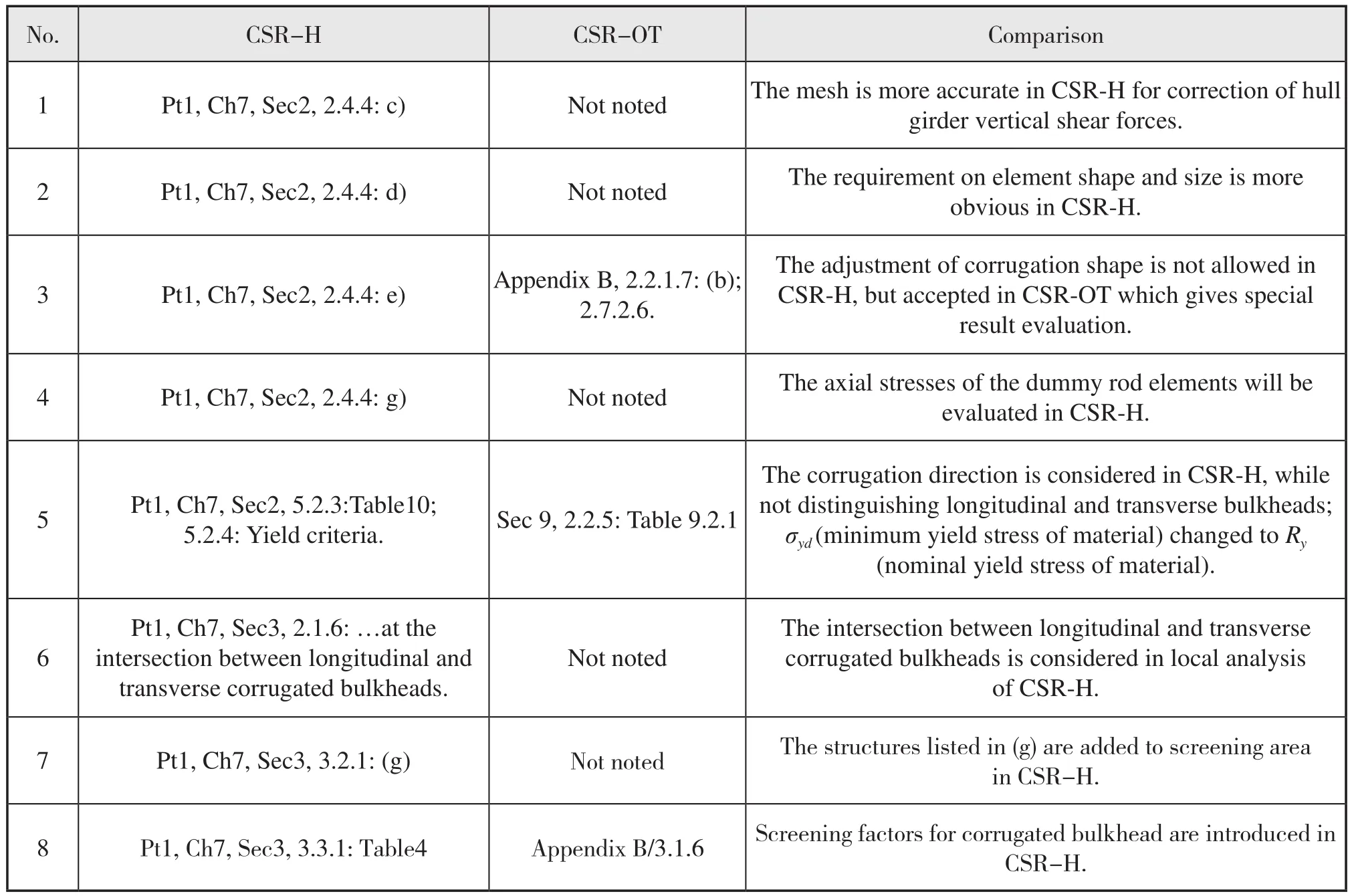
Table2 Differences about direct strength analysis (yielding assessment, midship)
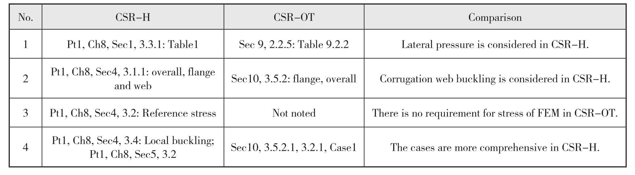
Table3 Differences about buckling assessment
Details in No.4 difference:
CSR-H: The buckling utilisation factor of flange and web of corrugation is based on the combined axial compressive and shear stresses.The combinations of two normal stresses and shear stress are to be considered.The interaction curve of plate buckling assessment is used with aspect ratio of the plate panelα=2 and edge stress ratioψ=1.
CSR-OT: Local buckling of a unit flange of corrugated bulkheads is controlled according to the uni-axial buckling of plates, with only case 1 (normal stress along the long side) andψ=1.
2 Local Scantling Analysis
From the comparison in 1.1, there are mainly two factors influencing the local scantling between CSROT and CSR-H for vertical corrugated bulkhead with lower stool:Ciat the upper end oflcgfor calculating vertical bending moment, and the design loads.
115k DWT product oil tanker, built in Longxue shipyard, is a typical large Aframax product oil tanker,with longitudinal and transverse vertical corrugated bulkheads, and lower and upper stools.
The design loads are calculated on three vertical sections (two ends and middle) for each longitudinal and transverse corrugated bulkhead in one cargo tank of this tanker, shown in Fig.1 and Fig.2.
The local scantling results (net required plate thickness along the height) are shown in Fig.3 and Fig.4.The corrugation is mainly rolled by line heat forming.
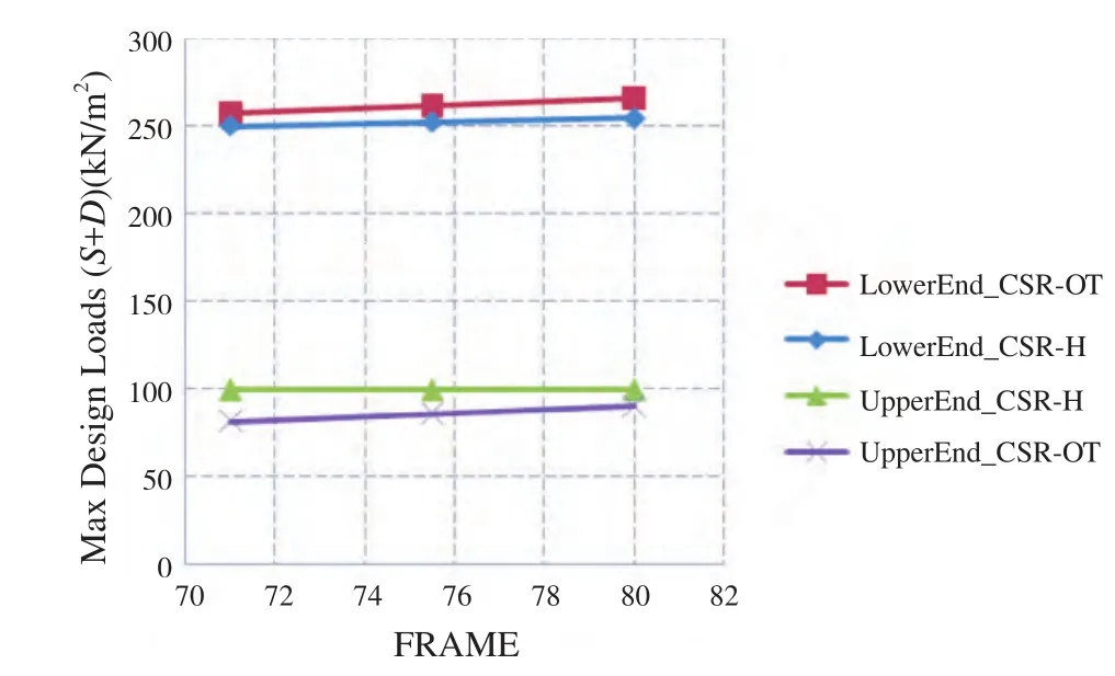
Fig.1 Maximum design loads(longitudinal corrugated bulkhead, No.4 cargo tank)
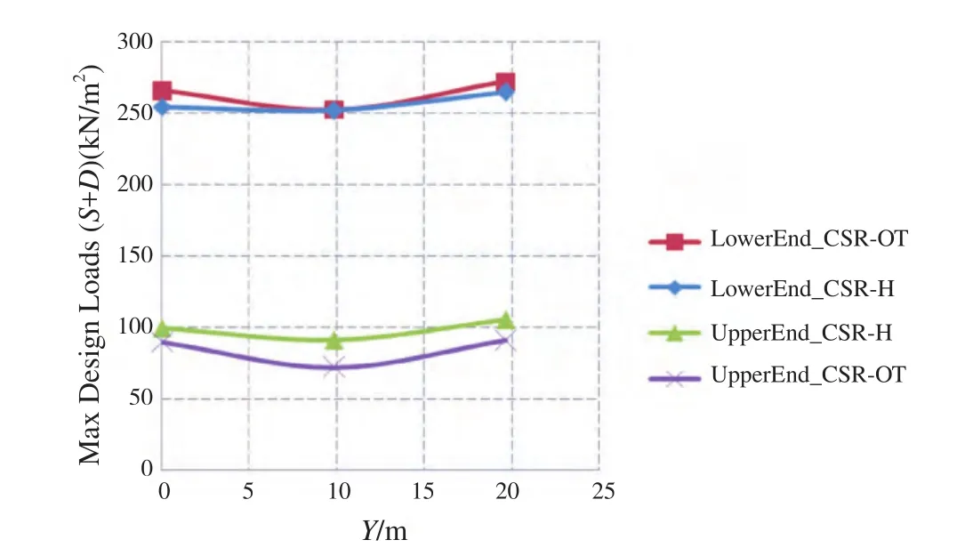
Fig.2 Maximum design loads(transverse corrugated bulkhead, FR80)
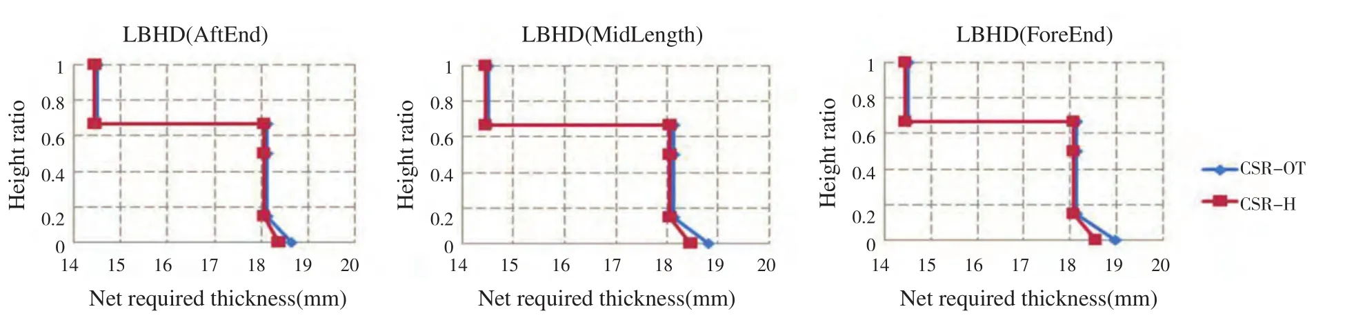
Fig.3 Results for longitudinal bulkhead

Fig.4 Results for transverse bulkhead
For the longitudinal bulkhead, the results(scantling requirements) in the middle and upper part are very close between CSR-OT and CSR-H, but at the lower end it is lower for CSR-H than CSR-OT.The results at the lower end are determined by the local design loads, which are lower for CSR-H than CSR-OT at the lower end.The results at the middle and upper part are determined by the section modulus requirement, of which the key factor is the average load of lower and upper end at ends of the tank.It can be seen that the average loads of lower and upper end are not different significantly between CSR-OT and CSR-H in Fig.1.
For the transverse bulkhead, the results at the middle and upper end are higher for CSR-H than CSROT, but at the lower end it is lower for CSR-H than CSR-OT, or similar.Like longitudinal bulkhead, the results at the lower end are determined by the local design loads.The results at the middle and upper end are also determined by the section modulus requirement, of which the key factor is the average load of lower and upper end at thebtk/2 vertical section(btkis the breadth of the tank).It can be seen that the average load of lower and upper end at thebtk/2 vertical section is higher for CSR-H than CSR-OT.The results at the position a little higher than 2/3 height of corrugation may be determined by the local design loads at the position.
It is found that the main factor influencing the result is the local design loads.The results at the lower end are normally determined by the local design load at the lower end, and the results at the middle and upper end are normally determined by the average load of lower and upper end.TheCivalue can influence the section modulus requirement at the upper end, and have no influence on the results.Because the thickness induced by the section modulus at the upper end shall not be less than 80% of the required thickness at the lower end.
If the local design loads are the same for CSR-H and CSR-OT, it is found that the required thickness results are also the same.
3 Direct Strength Analysis with Coarse Mesh
3.1 General
The cargo tank structural strength analysis of this 115k DWT product tanker is performed both according to CSR-OT and CSR-H.The two FE models are almost the same.The corrugation is to be modelled in accordance with its geometric shape, and the mesh on the stool in way of the corrugations is adjusted correspondingly.There are two elements for typical flange breadth and web height in general.The only difference of the two models is that the dummy rod elements with a cross sectional area of 1 mm2are modelled at the intersection between the flange and the web of corrugation in the model for CSR-H.
3.2 Yielding Assessment
The most critical results for longitudinal and transverse corrugated bulkhead are shown in Table4 and Table5.The ratio of yield factor shall not be greater than 1.
It is found that the assessment results according to CSR-H are a little higher than that of CSR-OT.Although the stress is higher, the assessment results of rod elements are a little lower than that of shell elements due to the different permissible yield factors.
Because of the same mesh and properties, the main factors influencing the results include the load casesand criteria.It is too complex to analyze the load cases.So the analysis of criteria could be performed with the same stress, which is shown in Table6 and Table7.The analysis is only for shell elements, and assumed that theVon Mises stresses are all 100 N/mm2.
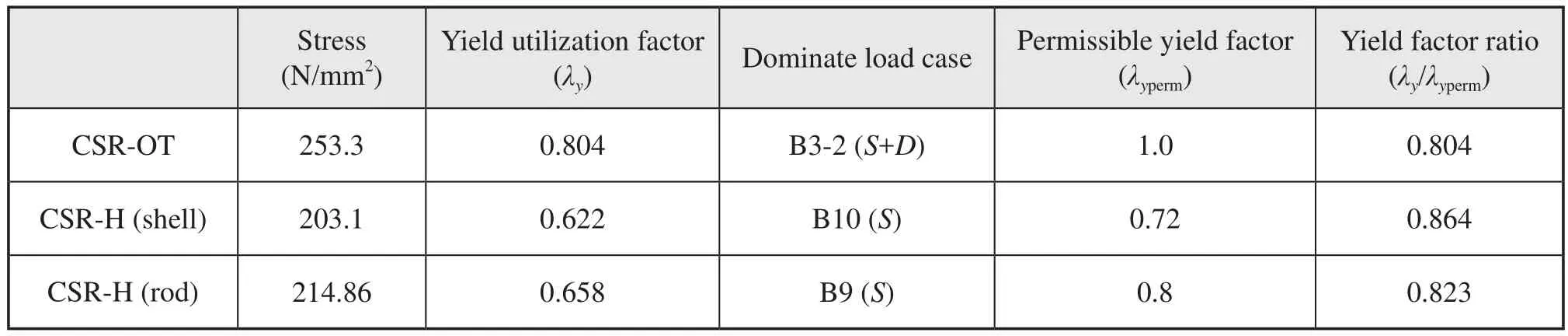
Table4 The most critical yielding assessment results (longitudinal bulkhead)
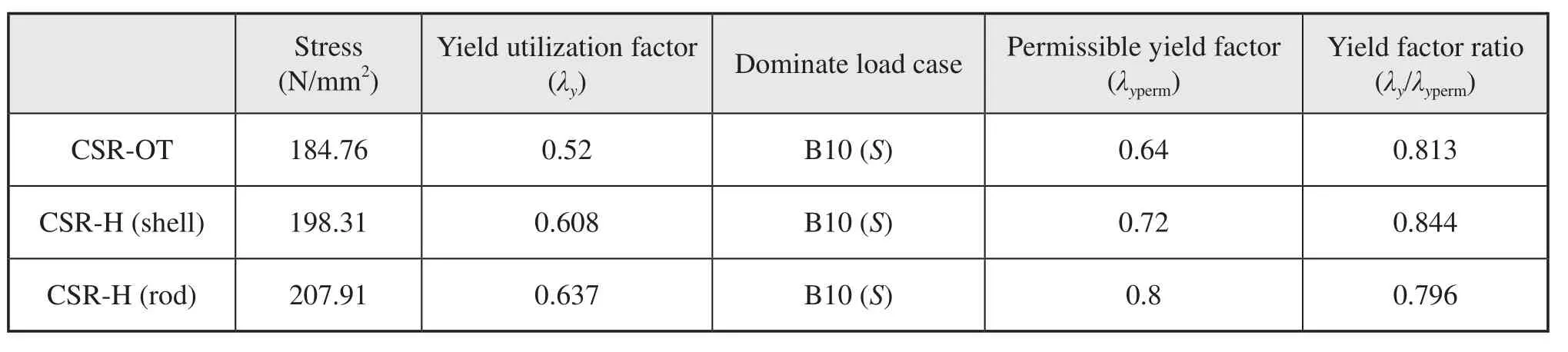
Table5 The most critical yielding assessment results (transverse bulkhead)
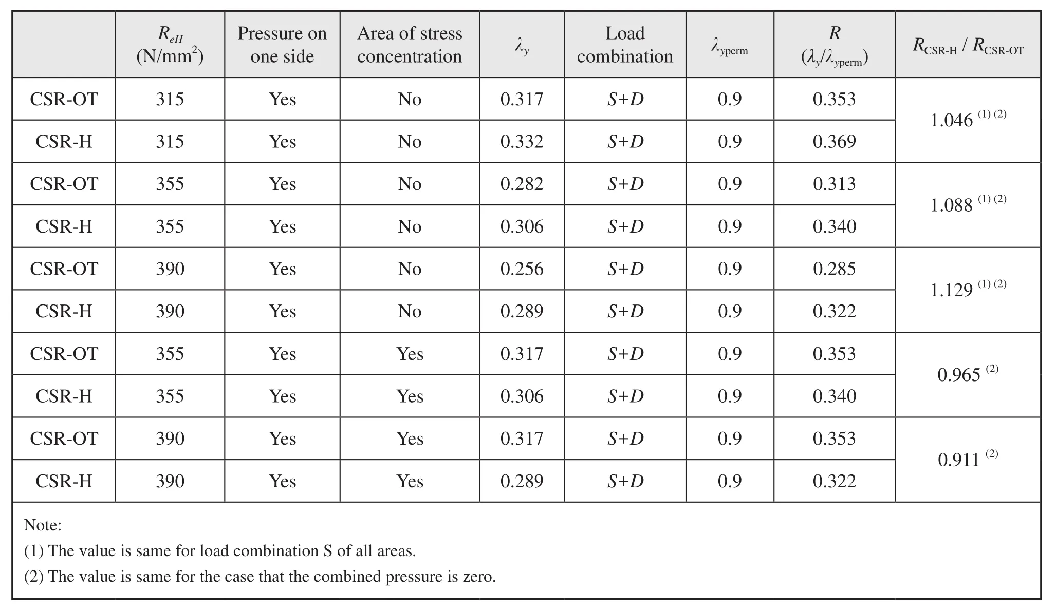
Table6 Yield criteria analysis (longitudinal bulkhead)

Table7 Yield criteria analysis (transverse bulkhead)
The material withReH=390 N/mm2, which is not present in this tanker but allowed in the rule, is used for comparing.It could be found that the main factors influencing the results (RCSR-H/RCSR-OT) include material yield stress and area of stress concentration.In general areas, the higher material yield stress is, the more severe for CSR-H than CSR-OT.But for areas of stress concentration inS+Dload combination, it is opposite.There are more advantages for transverse bulkhead than longitudinal bulkhead in the transition of criteria.
3.3 Buckling Assessment
The local buckling assessment results for longitudinal and transverse corrugated bulkheads are shown in Fig.5~6.The overall column buckling analysis is not needed for such tanker.

Fig.5 Buckling results of longitudinal corrugated bulkhead(No.4 cargo tank)

Fig.6 Buckling results of transverse corrugated bulkhead(FR80, from inner side to inner side)
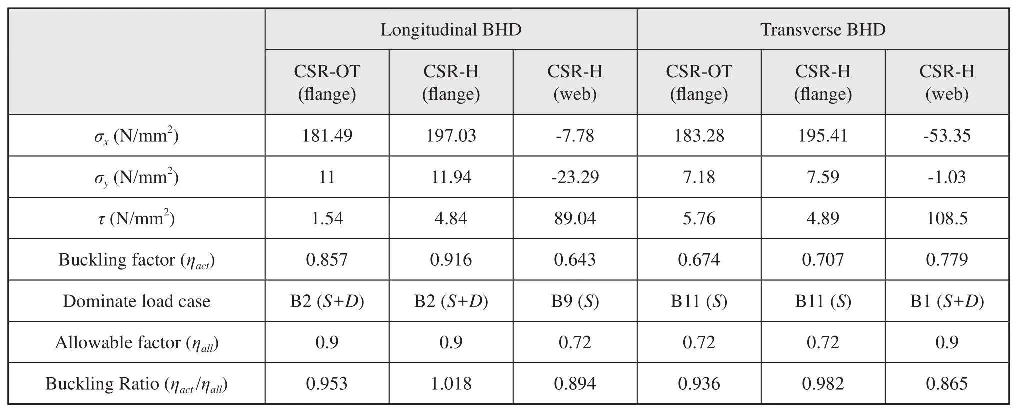
Table8 The most critical buckling assessment results
The most critical assessment results for longitudinal and transverse corrugated bulkhead are shown in Table8.The normal stress is signed as positive when compression andσxis the vertical stress.
The result distributions along the breadth of bulkheads are similar: for flanges, the results are higher in middle part than end position, but reverse for webs.Because the scantling requirement of flange is mainly determined by vertical normal stress, which is higher in middle part;the scantling requirement of web is mainly determined by shear stress, which is higher at end of bulkhead.Other factors (e.g.thickness) can also change the results.The buckling factors of web are reduced at the ends of longitudinal corrugated bulkhead due to the plate thicknesses increasing.
From the results shown above, it could be found that the buckling factors of flange are higher for CSR-H than CSR-OT, especially for longitudinal corrugated bulkhead (enhanced about 7%).The corrugation scantlings in the middle and upper part are normally determined by the buckling assessment results.The thicknesses of some parts of longitudinal corrugated bulkhead is increased by 0.5 mm in this tanker applying with CSR-H.
4 Local Fine Mesh Analysis
The local fine mesh analysis at the intersection of longitudinal and transverse corrugated bulkheads near lower stool is carried out applied with CSR-OT and CSR-H.

Fig.7 Local fine mesh model
The local sub model extent is shown in Fig.7.
The original gusset plate arrangement is shown in Fig.8.
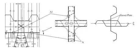
Fig.8 Original gusset plate arrangement
It is found that the local stresses around point A and A1 (intersection of corrugation corner and stool plates) are very high (symmetrical location similar),which are shown in Table9.The maximum stresses,although satisfy the criteria, shall be shaken down considering the potential building problems and cracks.The stress concentricity due to geometry discontinuity is very high around point A.Increasing thickness is not an effective way to solve the problem, as the plate is already very thick.The stresses of similar positions at longitudinal bulkhead are low due to the gusset plates.So the best way to reduce the stress is adding gusset plates.
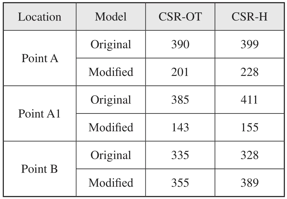
Table9 Maximum Von Mises stresses N/mm2
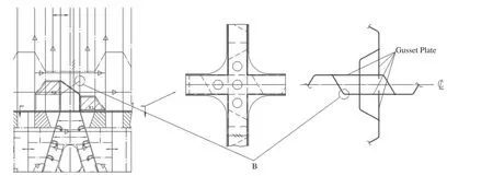
Fig.9 Modified gusset plate arrangement
The modified gusset plate arrangement is shown in Fig.9.
The maximum Von Mises stresses for the two models are shown in Table9.
The stresses at point A and A1 reduce about a half after adding gusset plates.Although the maximum stresses at point B (intersection of corrugation corner and shedder plate) are higher than original design, but lower than that of point A and A1 of original design.The stresses at point B may be reduced by changing the sloping angle of the shedder plate or the height of gusset plate.
The scantling of lowest part of corrugation is determined by the local fine mesh analysis results.Most areas can satisfy the requirement by increasing thicknesses except the area near the intersection of longitudinal and transverse corrugated bulkheads in way of lower stool.Proper gusset plate design shall be considered.
5 Conclusion
From the structural analysis of corrugated bulkheads of the 115k DWT product oil tanker above,
The conclusion will be shown as following.
(1) The local scantling requirements are similar between CSR-OT and CSR-H, while the design load is the main factor influencing the results.
(2) The results of CSR-H are generally a little higher than that of CSR-OT from the direct strength analysis mainly due to the higher design loads.The new requirements of rod element and web buckling assessment have no influence on the final results in general, but shall also need paying attentions.
(3) In coarse mesh analysis, for general areas (not stress concentration), higher yield strength will give more severe yielding results for CSR-H than CSROT, but for areas of stress concentration inS+Dload combination, it is opposite.There are more advantages for transverse bulkhead than longitudinal bulkhead in the transition of criteria.
(4) The corrugation scantlings in the middle and upper part are normally determined by the buckling assessment results.The buckling assessment results of flanges are mainly determined by vertical normal stress, higher in the mid breadth of tank, while the results of webs are mainly determined by shear stress,higher in the end of tank.There may be little thickness increasing for the longitudinal corrugated bulkheads applying with CSR-H.
(5) The scantling requirements of lowest part of corrugation are determined by the local fine mesh results.More attentions shall be paid to the area around the intersection of longitudinal and transverse corrugated bulkheads in way of lower stool.Adding proper gusset plates is more effective than increasing thickness for reducing the maximum stress level of this area.
[Reference]
[1] Hayato Suga, Tatsuya Hayashi, Shinichiro Ishimaru, et al.Design Development of Corrugated Bulkheads [C].Nippon Kaiji Kyokai (ClassNK).TSCF 2010 Shipbuilders Meeting.Tokyo.
[2] IACS.Common Structural Rules for Double Hull Oil Tankers [S].July 2012.
[3] IACS.Common Structural Rules for Bulk Carriers and Oil Tankers [S].External Release 1 Apr 2013.
[4] IACS.Common Structural Rules for Bulk Carriers [S].July 2012.
[5] IACS.Common Structural Rules for Double Hull Oil Tankers [S].July 2010.
[6] IACS.Common Structural Rules for Bulk Carriers and Oil Tankers Technical Background Rule Reference [S].External Release 1 Apr.2013.
