An Automatic Control System for Changing Feeds Based on Fuzzy PID and Laser Ranging
2013-12-16AiliYusupLiYongjiangSunZengwuGuoShaoguang
Aili Yusup, Li Yongjiang, Sun Zengwu, Guo Shaoguang
(1. Xinjiang Astronomical Observatory, Chinese Academy of Science, Urumqi 830011, China, Email: aliyu@xao.ac.cn; 2. Key Laboratory of Radio Astronomy, Chinese Academy of Sciences, Beijing 100049, China)
1 Introduction
Automatic control systems for changing feeds are given importance in the current world-wide advanced designs of radio telescopes (such as the GBT 100-meter radio telescope and the German 100-meter radio telescope). The reliability of such a system has a direct effect on the efficiency of using the radio telescope and observing time. Aging hardwares, mechanical switchs, manual lift operations, and conventional PID controllers make feed positioning precision very low, affecting the efficiency or accuracy of replacing/positioning a feed. Therefore, it is of urgent need to devise automatic feed changing systems that can move fast, position feed precisely, communicate reliably, gather information efficiently, and be operated conveniently. Such systems are useful for fully tapping the potential of telescopes to improve the observation efficiency. In this paper, we give a design of a computer control system to achieve fast, accurate, and stable change of feeds in real time. Users of the system can view the working status of each feed and the records of any lift operations. The system is operated through automatic remote control. The PC of the system not only can receive information of all brakes, contactors, and feeds collected through lower-end computers, but also can act upon the feedbacks of the lower-end parts and send appropriate commands to automatically replace feeds. The system has a friendly and highly reliable user interface.
2 Hardwares
Five feeds are stored and set for use with electric currents of other parts properly separated. The feeds are connected to the antenna and are placed at the center of a cone-shaped chamber for high-frequency equipments. Except the ones for the 1.3cm and 2.8cm wavelengths the feed are supported separately. Using four rails and precision lead screwdrivers fixed on the wall of the equipment room, the DC motor can drive the feed cabin to slide along the rail and move the needed feed (s) to the Cassegrain focus, while other feeds are placed at the storage positions. The automatic feed positioning with the switching system adopts laser distance sensors and digital closed-loop control, guaranteeing precise and rapid positioning.
The feed control system treats sensors, switches, motors, and limit switches of a feed like objects for observation, realizing the logic control of multiple feeds from the upper-end machinism. The hardware structure of this system is shown in Figure 1.

Fig.1 Hardware Structure
This system includes an antenna control unit (ACU) and an antenna drive unit (ADU). The system parts are connected with a local area network (LAN), which makes it convenient for authorized LAN users to check the states of feeds. The ACU (including a control computer, a serial-port board, a laser-ranging distance gauge, etc.) is in charge of reading data from the distance gauge, performing digital PID operations according to the data, and sending instructions. Through the running of its motor the driving system puts the feed at the work or storage location. One type of laser range finders are of PT5070S, with a detection range 30mm-100mm, a resolution less than 0.1% MBE, an accuracy less than 0.25% MBE, a 2.5KHz measuring frequency, and an output interface mode RS485. The main task of the drive unit of the DC servo motor (with the speed unit, power amplifier, corresponding speed control system, etc.) is to amplify the control signal and to drive the DC motor. The governing system includes motor controllers, control circuit protection, low-voltage devices, terminals, and other hardware devices. The control circuit protection adopts the SIEMENS S7-200 PLC. The PLC is of compact design, good scalability, low price, and strong orders. These can perfectly meet the needs of small-scale control, and ensure strong adaptability of the extension module.
If we use an RS232 protocol to link between the ACU and M&C, the data will be easily lost during the long-distance transmission, so we use the RS485 serial communication protocol with a bit rate of 9600bps. Meanwhile, in order to understand the details of feeds, a C/S model is used and a small client program is developed for the convenience of LAN users.
3 System Software
3.1 User-Interface Design
As shown in Figure 2, the interface of the control software is simple and easy to operate. Under the design principles for the “StayOnTop” type of dialog applications, the interface will be refreshed every 200 milliseconds.
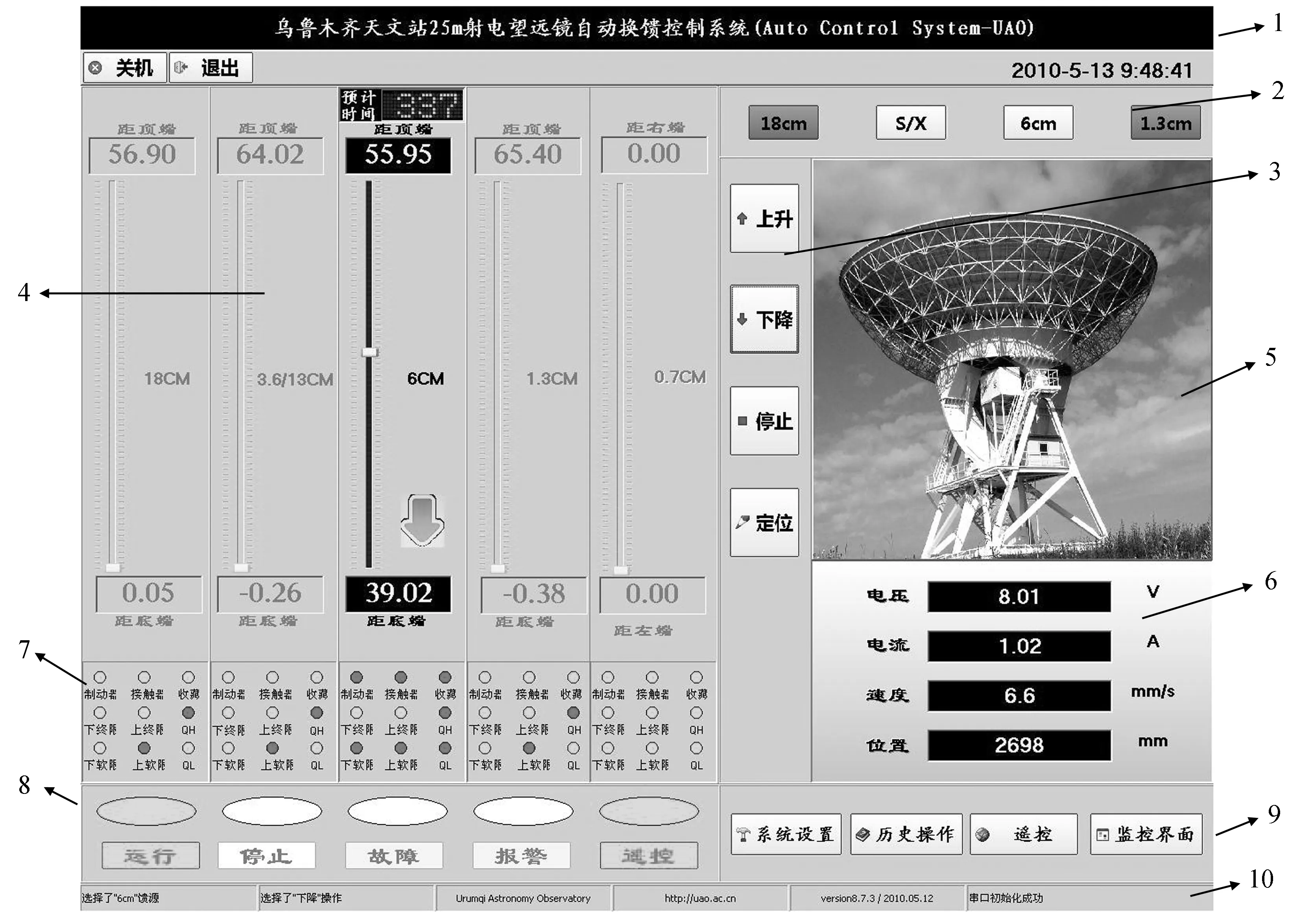
Fig.2 User interface of the control system of automatic change of feeds. The numbers beside the arrows are the indices of modules in the listing of the text
The interface has the following parts.
(1) The Main-Title Display Module: To display the title when a program is created.
(2) Feed-Selection Module: To select one of the four feeds to be in the working position.
(3) Feed-Operation Module: To move and stop the selected feed.
(4) Laser Range Finder Display Module: This module displays time required for feed lifting, the sliding bars showing the feed locations, and a direction arrow showing the dynamic movements of a feed.
(5) Video Surveillance Module: For user(s) to observe the real-time movements of a feed through a camera.
(6) Motor Information Module: This module displays the information of voltage, current, velocity, and position of a drive motor.
(7) Feed-Status Information Module: This module shows the information of the brakes, contactors, storage, final limits, QH, and QL of the feeds. Through the module users can easily determine the status of all the feeds.
(8) System-Status Module: This module includes running, stop, fault, alarm, and remote-control display sub-modules. In Figure 2, the 6cm feed is in the status of dropping, and all the remote-control and running information is displayed in green. If there is an error, the fault and alarm sub-modules will start and sound the alarm.
(9) Setting Module: User(s) can set the system parameters and view the operation history, remote control, and monitoring interface. This module can be adjusted by setting a series of communication parameters based on examining operational messages.
(10) Status -Bar Module: A module at the bottom of the interface to show the information of the selected feed, its operation, and the network serial-port initialization.
The control interface as shown in Figure 2 also serves as a remote-monitoring controller, which can receive query commands from a remote client and return the numerical values provided by the agreement on time (within 200ms). A client only receives the simplest information of settings, connection, and the feed status, which is for inspection, as the client cannot operate the feeds.
When the user clicks the connection button, the monitoring program will establish a network for the remote client. The client will carry out query operation to the server in every 200ms, and the server will return the required information to the client for unpacking and analyzing, including the display of the status of each feed (see Figure 3).
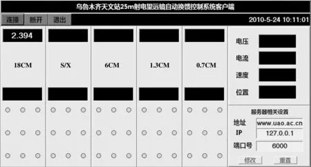
Fig.3 The client application of the control system of automatic change of feeds
3.2 Software-architecture design
The reading and writing from the software through the network serial port are with the PComm space operated at the frequency of 5Hz. The frequency for the information display on the interface is set to 3Hz. The software adopts the command format of “inquiring data→returning information.”When the serial port receives data, it trigges the OnReceiveData (), and the data will be accessed and analyzed by the OnReadBuffer ().
3.3 Main Functions and Features
The serial communication adopts the Pcomm of MOXA. The algorithm comes with a number of serial- communication functions of the sio_xxx () type, which allow us to set the serial port.
(1) Serial-port read and write functions.
1) sio_open (port) and sio_close (port): To open and close the serial port, respectively, with theserial port for set in the argument “port;”

Fig.4 Florchart of the software of the control system of automatic change of feeds
2) sio_ioctl (int port, int baud, int mode): To set serial-port baud rate, data bits, parity, etc.;
3) sio_write (port) and sio_read (port): To write and read through the port, respectively:
4) sio_cnt_irq (int port, VOID (CALLBACK*func) (int port), int count): To interrupt the port when triggered by the presence of data in the serial port.
(2) C/S application function
We use the TCP/IP protocol for the development of Client-Server application programs. The TclientSocket and TserverSocket components are used to manipulate the links and commincation between the client and the Server Socket. Though by itself not a Socket object, the TcustomwinSocket component is used to manipulate the Socket objects. By setting the Host Properties, the Adress property, and the port numbers of the server and the client, users can properly run the communication programs. With the SentText, the client can launch query requests from the server.
4 Laser-positioning technology and fuzzy PID control
4.1 Principle of laser positioning
In laser positioning a laser signal is sent to and reflected from the object, and the distance of the object is calculated according to the time difference between sending and receiving the signal. So together with the direction measurement the object can be positioned relative to the laser. The direction of the object is determined from the pointing of the laser. The measured position of an object can be transformed into standard coordinates (usually with GPS-positioning or user-defined coordinates of the laser). There are two types of laser range finders, pulsed laser range finders and phase-shift laser range finders. A phase-shift laser range finder uses the frequency in the radio range to modulate the electromagnetic waves of the laser beams, and determines the phase delay caused by the round trip of the modulated light (Figure 5). According to the wavelength of the modulated light, the phase delay can be converted into the distance. In this type the time required for the round-trip of the light is indirectly measured.
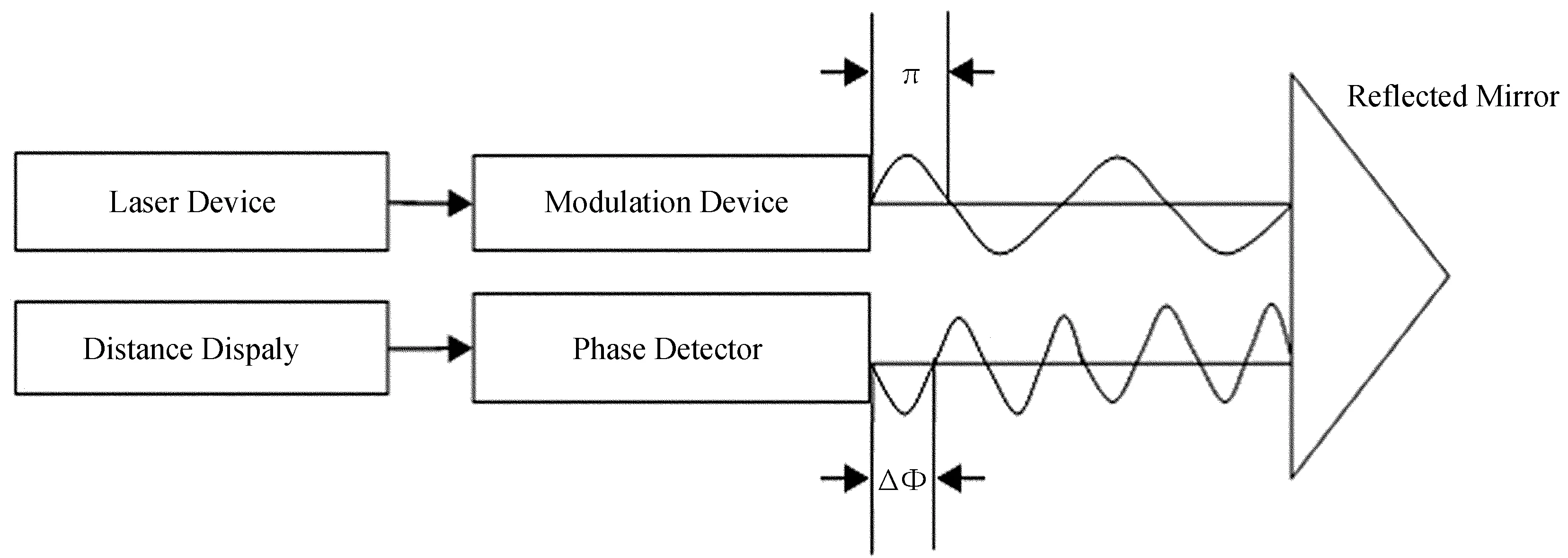
Fig.5 Principle of a phase-shift laser locator
Considering its general applications and the high precisions (on the level of millimiters), we choose this type of laser range finders. In order to have signals reflected effectively, and to have the targets be found precisely, we attach reflectors to the targets.
As shown in Figure 6, for collecting information of location and speed of the feeds, the laser range finders are installed at the switches of the upper- and lower-limit positions of the high-frequency equipment storage. A PT5070S laser range finder uses simple statistical prescriptions (e.g. the averaging method) to achieve the resolution of 0.05mm and to ensure the response speed. Such a range finder outputs a digital signal, and the output conversion function is
Laser [i]= (WORD)(((WORD)Com_buffer0 [i]. Input_buf [3] & 0x3f)<<6)+(WORD) (Com_buffer0 [i]. Input_buf [4] & 0x3f) .
Here, Laser [1] is the returned array as defined, and Com_buffer0 [i] is for the data from the ith serial port. This information can be transmitted directly to the control unit for processing and display in the terminal control interface. The connection mode is the RS485.
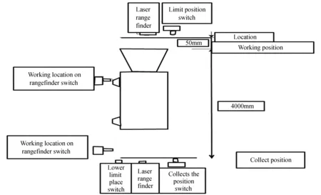
Fig.6 Schematic diagram of laser positioning
4.2 Advanced PID algorithm
In the actual program, a PID controller becomes one of the main technical components in process control and servo control because of its simple structure, stability, reliability, and easy operation. A PID controller is essentially a linear controller. Through a linear combination it forms a quantity depending on the deviation signal, and its time integral and differential. It controls the object based on the values of the quantity. When the structure and parameters for controlling are not fully understood, there is a lack of accurate mathematical modeling for controlling, or the technologies of control are too complex to be used, so the structure and parameters of the system controller must rely on experience and on-site debugging to be determined. The PID control technology can provide the convenience for empirically adjusting such settings. Below, Equation (1) outlines the quantity in a traditional PID controller; the transfer parameters of PID are shown in Equations (2) and (3).
(1)

(2)
(3)
Here,KPis a proportional coefficient,TIis a constant for integral over time, andTDis a coefficient for the differential with respect to time. Because of the multi-variables, strong coupling, and hardware complexity of the system, it is difficult to determine the PID parameters accurately. A new and stable control method the fuzzy control can help to overcome the difficulties, though. The fuzzy PID control combines the advantages of PID control and those of fuzzy control. Our PID controller has an attached fuzzy control system, which guides the main PID control. By repeatedly adjusting the parameters as shown in Eqs. (1) through (3), the controller achieves better performance than conventional controllers, and has great improvement in the controllability, adaptability, and effectiveness of the algorithm. It can also eliminate the limit-cycle oscillation.
The principle of a fuzzy PID controller is shown in Figure 7. The “Fuzzy rules and reasoning” in the figure is a logic module, which plays an important role in establishing the membership function and determining the fuzzy relations (see Figure 8). The key of fuzzy PID control is to find the the three parameters of PID, the error e, and the fuzzy relation of the error variationEc. According to the systematic error and the variation size of the error, it can automatically and timingly adjust the three parameters. Because of the use of phase-shift laser range finders, the error e is reduced to a low level. Therefore, what becomes an issue is how to reduceEcand keep it stable.
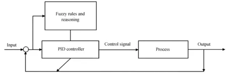
Fig.7 Schematic diagram of the fuzzy PID control system
The mathematical model of an electrical motor is a representative second-order system, and the core of fuzzy controller is the setting of fuzzy control rules. The key of our design is to choose the correct and stable control rules. According to the mutual influences between the three parameters, we set fuzzy control rules as in Table 1. We set the three control parameters as KP=3, KI=0.03, and KD=0.002. Figure 9 shows the error response of fuzzy PID control, and Figure 10 shows the comparison between the outputs of the conventional PID control and the fuzzy PID control. The three parameters of PID, meanwhile, are adjustable through the network interface. Our simulations show that an optimized fuzzy PID response curve can reach its stablity faster than a traditional PID response curve, and the less We can get the optimal result by adjusting the three parameters of PID. We use the MATLAB to simulating fuzzy PID functions, as shown in this plot. The blue line is for the optimal fuzzy PID control, and the red line is for the convention PID control oscillating range can reduce the risk of zero-point drift in the output. The advantages of the fuzzy PID control according to the simulations can be summarized as follows.
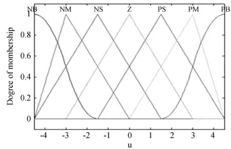
Fig.8 Degrees of membership for different values of various parameters.
(1) Compared with conventional PID control, the fuzzy PID control model has smaller overshoot, high steady-state accuracy, and shorter response time. The fuzzy PID control can also be stabilized in a very short period of time.
(2) When there is external interference, the error of conventional PID control is enhanced. In contrast the fuzzy PID control has strong counter-interference capability, which can help the system to adapt to different circumstances.

Table 1 Table of fuzzy rules ΔKP/ΔKI/ΔKD

Fig.9 Error in the response of the fuzzy PID control
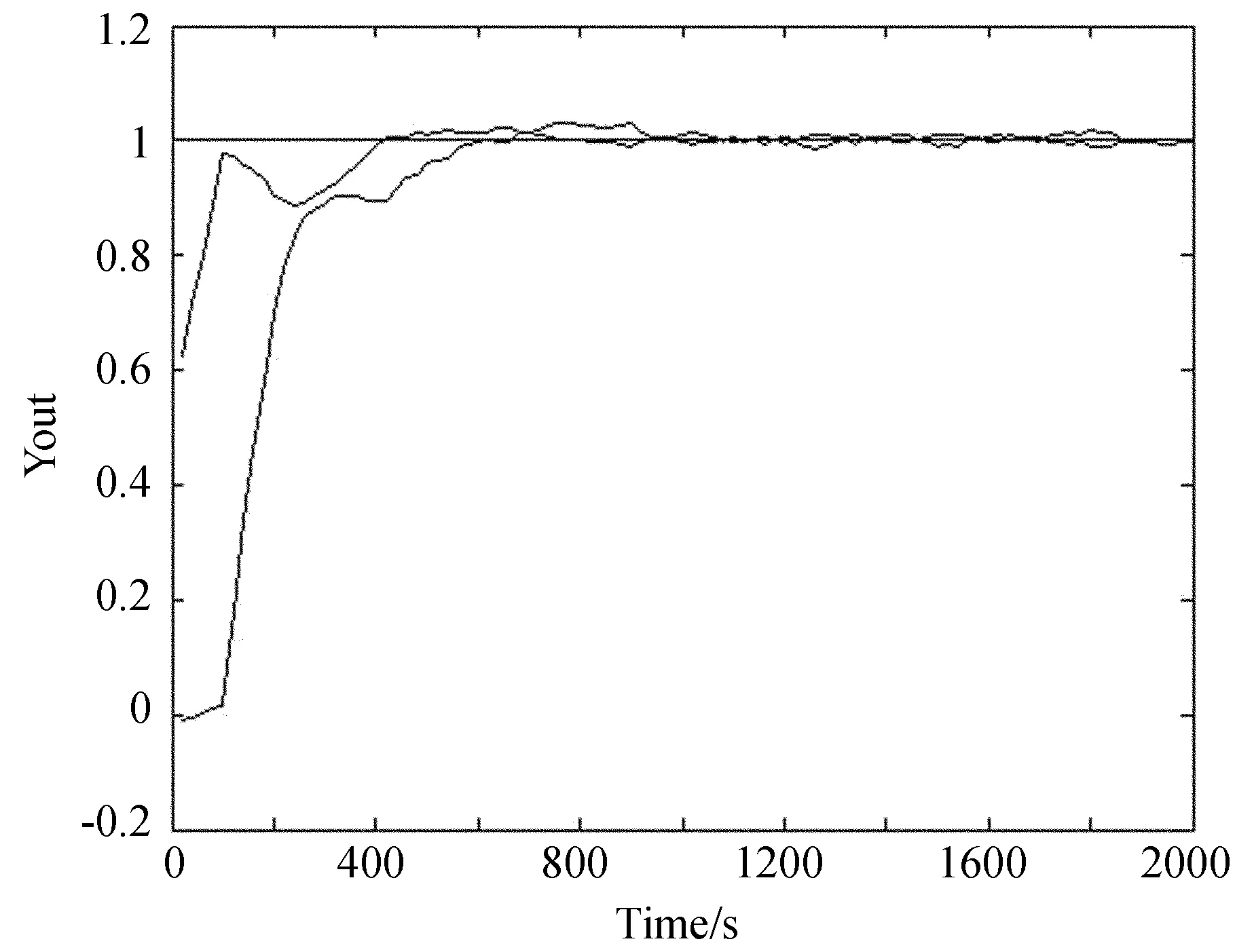
Fig.10 Comparison of the outputs of the fuzzy PID control and the conventional PID
Using the fuzzy PID control the system has successfully achieved real-time adjustment of the feeds. For the control system, we use nonlinear membership functions, with the fuzzy control for coarse adjustment and the PID for further fine-tuning. The PID starts from the zero point set by the fuzzy control to approach highly accurate adjustment.
5 A Summary of the performance of the automatic control system for changing feeds
(1) The application of the laser-range technology allows the positioning accuracy of a feed to be on the order of magnitude of 0.05mm.
(2) The automatic-control software effectively includes astronomical applications. This can be helpful to various fields of astronomy.
(3) Our fuzzy PID control takes the full advantage of the fuzzy control and conventional PID control, to enhance the robustness, adaptive capacity, and accuracy of the control system. The system performance is thus optimized to meet the needs of receiving weak radio signals.
(4) The capacity of the fuzzy PID control of feeds is improving with the accumulation of data and is becoming stable. Reasonable control parameters for the PID controller are thus available to keep the system in an optimal state.
The automatic control system for changing feeds greatly reduces the time for positioning feeds and improves the positioning accuracy of the feeds to ensure high efficiency of the antenna. The fuzzy control has greatly optimized the PID control algorithm. The system is overall robust, adaptive, and reliable. Our simulations and applications of it have yielded satisfactory results. The system is now used at the Nanshan site of Urumqi. We hope it could be applied in other stations in China.
[1]Y Li, W Feng, K C Tan, et al. PIDeasy and automated generation of optimal PID controllers[C]// Proceedings of The Third Asia-Pacific Conference on Measurement and Control, 1998: 29-33.
[2]Dai Qian, Song Wenwu, Wang Xijun. Design and stability analysis of high frequency LD’s driving circuit[J]. Optics and Precision Engineering, 2006, 14(5): 745-748.
[3]J Quevedo, T Escobet. Digital control: past, present and future of PID control[C]// Proceedings of the IFAC Workshop, 2000.
[4]J D Phillipsa, R D Reasenberg. Tracking frequency laser distance guage[J]. Review of Scientific Instruments, 2005, 76(6): 408-417.
[5]Hao Ying. Fuzzy control and modeling, analytical foundations and applications[M]. USA: Institute of Electrical and Electronic Engineers incorporation, 2000.
[6]Jin Weizheng. The new kind of 4-Wire temperature measure circuit using PT100[J]. Elect ronic Measurement Technology, 2000(2): 30-34.
[7]J G Ziegle, N B Nichols. Optimum settings for automatic controllers[J]. Transactions of the ASME, 1942, 64: 759-768.
[8]W S Levine. PID Control[J]. Nanjing: IEEE Press, 1996: 198-209.
[9]L Wang, T J D Barnes, W R Cluett. New frequency-domain design method for PID controllers[J]. IEE Proceedings Control Theory and Applications, 1995, 142(4): 265-271.
[10]He Q, Garvey S D. To automatically select PID structures for various electrical drive applications[J]. IEE Colloquium on Getting the Best Out of Pid in Machine Control, 1996(2): 1-4.