Simulations of THM processes in buffer-rock barriers of high-level waste disposal in an argillaceous formation
2013-11-30XioshuoLiChunlingZhngKlusrgenhlig
Xioshuo Li,Chunling Zhng,Klus-Jürgen Röhlig
aInstitute of Disposal Research,Clausthal University of Technology,Clausthal-Zellerfeld 38678,Germany bGesellschaft für Anlagen-und Reaktorsicherheit mbH,Braunschweig 38118,Germany
A R T I C L E I N F O
Thermo-hydro-mechanical(THM)coupling processes Clay formation Unsaturated porous media Bentonite buffer CODE BRIGHT
The main objective of this paper is to investigate and analyse the thermo-hydro-mechanical(THM)coupling phenomena and their in fl uences on the repository safety.In this paper,the high-level waste(HLW)disposal concept in drifts in clay formation with back filled bentonite buffer is represented numerically using the CODE BRIGHT developed by the Technical University of Catalonia in Barcelona.The parameters of clay and bentonite used in the simulation are determined by laboratory and in situ experiments.The calculation results are presented to show the hydro-mechanical(HM)processes during the operation phase and the THM processes in the after-closure phase.According to the simulation results,the most probable critical processes for the disposal project have been represented and analyzed.The work also provides an input for additional development regarding the design,assessment and validation of the HLW disposal concept.
©2013 Institute of Rock and Soil Mechanics,Chinese Academy of Sciences.Production and hosting by Elsevier B.V.All rights reserved.
∗Corresponding author.Tel.:+49 05323 724923.
E-mail address:xiaoshuo.li@tu-clausthal.de(X.Li).
Peer review under responsibility of Institute of Rock and Soil Mechanics,Chinese Academy of Sciences.
1674-7755©2013 Institute of Rock and Soil Mechanics,Chinese Academy of Sciences.Production and hosting by Elsevier B.V.All rights reserved.
http://dx.doi.org/10.1016/j.jrmge.2012.09.002
1.Introduction
Radioactive waste is a consequence of using radioactive materials in industrial,medical,military and research applications.For high-level waste(HLW),spent fuel(SF)and all long-lived waste categories,geological disposal at depths of some hundreds of metres is considered world wide as the most safe and feasible method to protect human beings and the environment for extremely long periods of time(IAEA,1993).
Clay formations are being widely investigated as host media for deep disposal of radioactive waste,such as the plastic Boom Clay in Belgium,the highly indurated Opalinus Clay in Switzerland and the Callovo-Oxfordian argillite in France.They are characterized by very low permeabilities of 10-19-10-21m2.The porosity varies from 0.14 to 0.37.Clays offer high sorption capability for most radionuclides.The plasticity and self-sealing/healing properties of most clay rocks also contribute to the restoration of pre-existing and excavation-induced cracks.All of these properties provide great advantages for reliable long-term con finement and isolation of radioactive waste from the biosphere.The disposal concepts rely on a multi-barrier system with natural geological barriers provided by the repository host rock and its surroundings and the engineered barriers within the repository.The capability of natural barriers for long-term isolation of radionuclides from the environment and their long-term stabilities are the key reasons for the geological disposal of radioactive waste.The engineered barrier system represents the man-made,engineered materials placed within a repository,including waste form,waste containers,buffer materials,back fill,and seals(OECD,2003).
The French repository designed by French ANDRA in 2005 is located in the middle of the Callovo-Oxfordian argillaceous formation(COX)of 250m thickness at a depth of 500-630m below the ground surface.In order to maximize the length of the radionuclide transport to adjacent formations both above and below the repository,horizontal disposal in drifts,rather than vertical disposal in boreholes,is selected.The HLW containers with 430mm in diameter and 1335mm in length will be emplaced in dead-end boreholes(700mm in diameter,40m long)with liner,as shown in Fig.1.These cells are spaced approximately 10m apart and each one receives 6-8 containers.The remaining space between HLW containers and cell walls will be back filled with compacted bentonite-based buffer materials.Due to the excavation,ventilation,back filling operation and the heat power of the emplaced HLW,the primary thermo-hydro-mechanical(THM)state of the clay formation with high water content will be disturbed.Thus,long-term THM processes should take place,which may have influence on the cofinement capability of the disposal concept against the release of emplaced radioactive materials.For this reason,a study of the long-term THM phenomena during and after the repos itory operation is necessary for the long-term safety assessment of the disposal concept.
Although bentonite buffer will probably not be used between container and drift wall in the most current French disposal concept,it is interesting to obtain the THM processes in the two media.The main objective of this paper is to investigate and analyse the THM coupling phenomena in the rock-buffer system surrounding heat-emitting radioactive waste.The results will support the performance and safety assessment of repositories in clay formations.
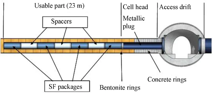
Fig.1.French concept for disposal of HLW in horizontal borehole(ANDRA,2005a).
2.Basic theories of THM modelling
2.1.THM coupling phenomena
Geological and geotechnical materials,like rocks and backfi ll/buffer materials,are porous media.Generally,the porous media are composed of three species:mineral,water and air,distributing in three phases:solid,liquid and gas(Fig.2).The liquid phase contains liquid water and dissolved air,while the gas phase is a mixture of dry air and water vapour.
In porous media subjected to hydraulic and mechanical conditions,complex THM phenomena and interactions take place.The THM processes of the porous media are coupled through some parameters.For instance,the heat transport(thermal)causes changes of the pore pressure and the fl uid viscosity,which have in fl uence on the water and gas flow(hydraulic).As shown in Fig.3,the parameters,such as thermal conductivity and effective stresses,are considered as the bridge parameters for the coupling of the THM phenomena.
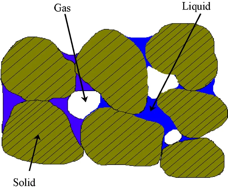
Fig.2.Schematic representation of an unsaturated porous material(CODE BRIGHT,2004).
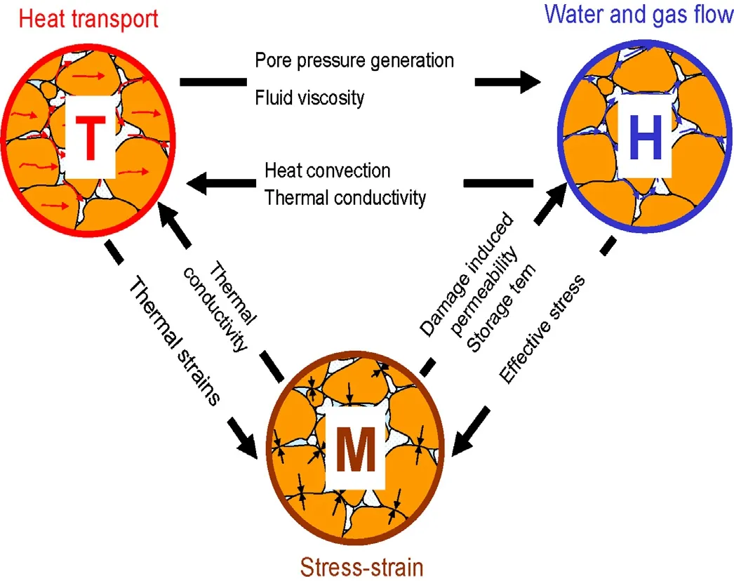
Fig.3.Mutual relationships between THM processes in a porous medium(CODE BRIGHT,2004).
The aforementioned THM phenomena have been implemented in the CODE BRIGHT.Details about the basic theories with the formulated governing equations are described in the code manual(CODE BRIGHT,2004)as well as other references(Olivella et al.,1994;Gens et al.,1998,2007;OECD,2003).In the following context,the balance equations and constitutive models,which are to be solved in the calculations,are brie fl y summarized.Values of the associated parameters for the Callovo-Oxfordian argillite and the FEBX compacted bentonite are taken from Gens et al.(1998,2007),OECD(2003),Vaunat et al.(2003),Zhang et al.(2004),and Zhang(2009).
2.2.Balance equations
Generally,for the calculations of coupled THM processes ingeological media,a set of balance equations for internal energy,solid mass,water mass,air mass,and stress equilibrium are to be solved in a consistent way.
2.2.1.Internal energy balance
The internal energy balance can be written as:
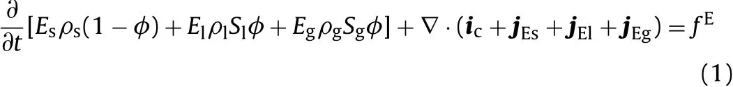
whereEs,E1andEgare specific internal energies corresponding to the solid,liquid and gas phases(J/kg),respectively;ρs,ρ1and ρgare the densities of the three phases(kg/m3);φ is the porosity of the total media;S1is the volumetric liquid fraction(%)andSgis the volumetric gas fraction with respect to the pore volume(%),S1+Sg=1;fEis the energy supply per unit volume of the considered media(J/s);icis the conductive heat fl ux;and jEs,jEl,jEgare the advective energy fl ux of each of the three phases with respect to a fixed reference system(J/s).The most relevant advection energy fl uxes correspond to vapour and liquid water motion.2.2.2.Water mass balance
The water mass balance can be written as:

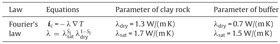
Table 1Thermal law and parameters for the rock and the buffer.
whereθlwandθgware the mass of water per unit volume of liquid and gas(kg/m3),respectively;jwland jwgdenote the total mass fl ux of water in the liquid and gas phases with respect to a fixed reference system(kg/(m3s)),respectively;andfwis the external mass supply of water per unit volume of media(kg/(m3s)).
2.2.3.Air mass balance
The air mass balance is expressed as:

where θlaand θgaare the mass of dry air per unit volume of liquid and gas(kg/m3),respectively;jaland jagindicate the total mass fl ux of air in the liquid and gas phases with respect to a fixed reference system(kg/(m3s)),respectively;andfais the external mass supply of air per unit volume of media(kg/(m3s)).
2.2.4.Solid mass balance
The solid mass balance is expressed as:

where θsis the solid density(kg/m3),and jsis the fl ux of solid(kg/(m3s)).
2.2.5.Stress equilibrium
The stress equilibrium is expressed as:

where σ represents the stresses(MPa)and b the body forces(kN).
2.3.Constitutive models and parameters
The set of the balance equations is completed by constitutive equations linking the state variables with the dependent variables,which are considered in CODE BRIGHT.The constitutive models describe the THM behaviours of the material.All the equations involve physical parameters,some of which also depend on the state variables of pressure and temperature.
Two materials are taken into account in this simulation work,thus a lot of material THM properties and parameters need to be considered.In this paper,however,only the important parameters are summarized.While clay rock is initially saturated by formation water(suction equals 0),the bentonite buffer has an initial saturation of 52%.
Heat transport is governed by conduction through the porous media and by advective flow of liquid water and vapour.Thermal conduction is expressed by Fourier’s law,as presented in Table 1.
Liquid and gas advection follows Darcy’s law:

where Kαis the hydraulic conductivity of each phase,α=l stands for liquid and α=g for gas; ∇Pαindicates the hydraulic gradient;and g is the gravitational acceleration.
The hydraulic conductivity of each phase depends on the intrinsic permeability k,relative permeabilitykrα,and dynamic viscosity μα.The hydraulic parameters depend on the material state,i.e.porosity,degree of saturation,temperature(see Table 1),etc.Thus,Kαcan be written as

Fig.4.Thermal conductivity of clay and bentonite as function of water saturation.
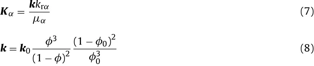
In the simulation,k0has an initial value of 1×10-20m2for both materials.The bentonite buffer has an initial porosityφ0=0.40 while φ0=0.16 for the clay formation.
The thermal conductivity depends on water saturation,as shown in Fig.4,for the buffer and the clay rock.The thermal conductivity increases with increasing water saturation.Additionally,because rock has a higher density,its thermal conductivity is larger than that of bentonite buffer.Fig.5 illustrates the relationship between the permeability and the porosity of the two materials.The porosity could be changed through the mechanical stress and damage,so that a coupling of hydraulical and mechanical processes is to be expected.Fig.6 shows the water retention curves of the two materials,giving the relationship between water content and capillary pressure in pores or suction.
The mechanical behaviour of compacted bentonite is usually described by a thermo-elastoplastic model named Barcelona Basic Model(BBM),whereas a so-called damage-elastoplastic(DEP)model is applied for the stress-strain behaviour of brittle clay rocks.Both models are implemented in the CODE BRIGHT.
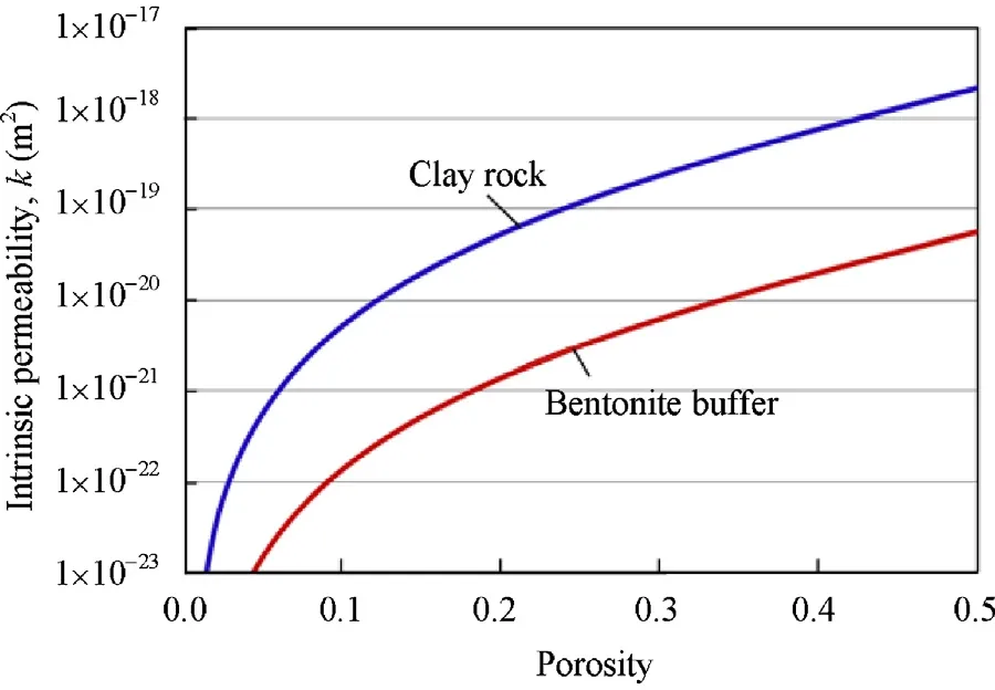
Fig.5.Permeability related to porosity for the clay rock and the bentonite buffer.
Many mechanical features of unsaturated soils can be represented by the BBM in a consistent and unified manner,such as swelling and shrinking due to moisture change,nonlinear elasto plastic deformation with strain hardening,increase in stiffnessand strength with decreasing water content,and thermal expansion/contraction by temperature change:
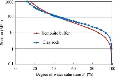
Fig.6.Water retention curves of the clay rock and the bentonite buffer.
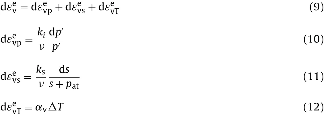
where ν is the Poisson’s ratio,p′represents the mean stress,s indi cates the suction pressure(minus liquid pressure in pore),patisthe gas pressure of the porous media,αvpresents the thermal expansion coef ficient,kiis the bulk modulus,and ksindicates the liquid swelling/shrinking coef ficient.As shown in Eq.(9),there are three parts of deformation in this model:εevppresents the strain from the mechanical stress,while εevsindicates the swelling/shrinking strain,εevTis considered as thermal expansion/contraction.
The FEBEX bentonite is a highly expansive material.When contacting with moisture or liquid water,the bentonite tends to swell.In order to represent the swelling behaviour of the bentonite,a simulation of a swelling pressure test has been carried out.Fig.7 shows the model of the swelling test on an unsaturated FEBEX ben tonite sample in a cell of 100m m in diameter and 30mm in height with a fixed volume.The bentonite has a porosity of 0.42,an initial degree of saturation of 23.8%,and a suction of 107MPa.The sample is wetted at the bottom by a constant water pressure of 0.1MPa.The swelling pressure at the central point of the sample is to be obtained.
Fig.8 presents the evolution of the swelling pressure of the constrained bentonite during wetting.The swelling property of the bentonite buffer is to be obtained clearly that the swelling pressure increases to 5.0MPa with water up-taking until the sample is saturated.
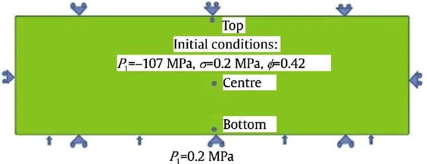
Fig.7.The model set of the bentonite swelling pressure test.
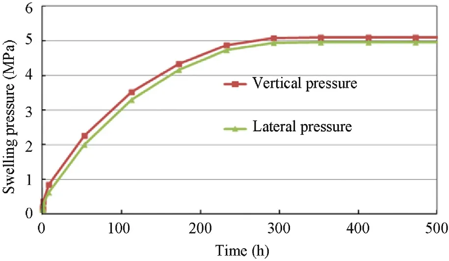
Fig.8.Evolution of swelling pressure in the constrained bentonite during wetting.
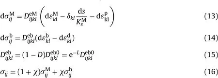
In the formulation of a DEP model(Vaunat et al.,2003;Vaunat and Gens,2004),a brittle clay rock is considered as a composite material made of a clay matrix connected by bonds(see Fig.9).
The clay matrix behaves like a typical elastoplastic soil(see Eq.(13)),while the bonds behave like a typical quasi-brittle material that can be represented by a damage elastic law(see Eqs.(14)and(15)).The stress-strain behaviour of the composite material is determined by coupling both responses of matrix and bonds under compatible conditions(see Eq.(16)).The model and the associated parameters are taken from the literature(Vaunat et al.,2003;CODE BRIGHT,2004;Vaunat and Gens,2004;Zhang et al.,2004;Gens and Olivella,2006;Zhang,2009).
随着信息技术的不断发展与升级,“微媒体”得到迅速发展,媒体传播已经告别了传统的传播方式,进入了全新的“微时代”。而且“微媒体”具有着这个时代得天独厚的优势,它的信息具有开放性、资源也具有高度的共享性、信息传播的途径更为广泛而且没有门槛限制。因为他独有的多元化、高效率、低门槛、灵活性受到广大群众的青睐。而作为当代的大学生,可以通过“微媒体”来填补自己精神层面的缺失,也可以利用它独特优势来宣传积极正能量的事情,通过这样的方式来不断培养自己的精神文明。

Fig.9.Schematic arrangements of clay matrix arrangements of bonds in clay rock(Zhang et al.,2004).
Eq.(16)shows the coupling behaviour of the bond and clay material in the clay rock.In case of fully damage(D tends to 1,L tends to∞),the rock behaves like the destructured soil(clay matrix).
Fig.10illustrates the yieldboundary of clay matrix and the damage locus of bonds in the clay rock.Inside the damage locus,no damage occurs,however,outside of this zone,loading produces degradation of elastic properties due to the destructuration of bonds.When the yield boundary of the matrix is attained,plastic deformation begins.In Fig.10,Rcis the uniaxial compressive strength,and m is the shape parameter of the yield locus.
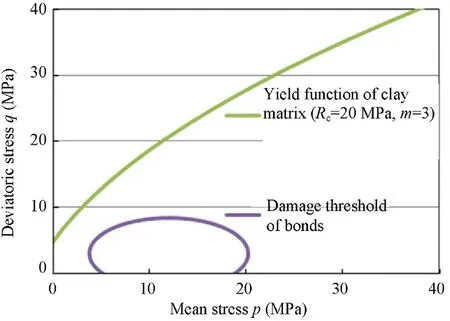
Fig.10.Yield boundary of clay matrix and damage locus of bonds in the clay rock.
3.Construction of the numerical model
Based on the French concept in 2005 for the direct disposal of HLW containers in horizontal drifts(Fig.1),one disposal drift is considered in this modelling work.This drift is considered to be excavated at a depth of 500m below the surface.It has a diameter of 2.2m and a length of 20m.After excavation,the drift will be ventilated for about 3 months.Four HLW containers of 0.39m in diameter and 1.7m in length each are emplaced in the 13.6m long middle space in a distance of 2.3m to each other.The remaining space in the drift will be back filled with compacted bentonite buffer.The buffer thickness between the container and the drift wall is 0.9m.A large volume of the rock mass around the drift is taken into account by an axisymmetric model of 100m in radius and 100m in length.In fact,this model represents a cylindrical rock-buffer system with the central axis of the containers,as shown in Fig.11.Some points are selected in the buffer and the rock along the radial line(dash yellow line)in the middle of the drift for recording THM parameters with time.
The materials are assumed homogeneous and isotropic for focusing on THM coupling processes in the rock-buffer system,even though the clay rock exhibits some anisotropic properties.Initially,the host rock with porosity of 0.15 is saturated with the formation water.The in situ prevailing conditions in the Bure URL(ANDRA,2005b)are applied to the model.An isotropic rock stress state is prescribed with a magnitude of 12.5MPa at the depth of 500m.A pore water pressure of 4.5MPa is assumed.The rock temperature is about 27°C.The atmospheric gas pressure of 0.1MPa is kept constant,i.e.the initial conditions are fixed at the boundaries of the rock mass over the modelling procedure including the drift excavation,ventilation,back fill,and heat emission from the waste.
In the first step,the drift excavation and ventilation is simulated by(1)reducing the stress normal to the drift wall down to zero,and(2)circulating gas along the drift wall with relative humidity of85%(gasdensity of1.194kg/m3,vapour mass fraction of1.005%)andthe turbulence coef ficient of 10-5m/s.The drift excavation and ventilation will take a time period of 100 days.The applied ventilation conditions are comparable with the observation in the Mont Terri URL(Zhang et al.,2007)(the conditions in the Bure URL cannot be found in the literature).In order to highlight the ventilation effects,an extra calculation is carried out for a longer time period of 2000 days.
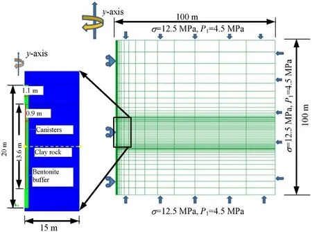
Fig.11.Model geometry for the French concept.
Following the drift excavation and ventilation,the HLW containers and the bentonite are emplaced in the drift.This is simulated by simultaneously applying the initial conditions of the buffer and the decayed heat emitting from the waste containers as thermal boundary conditions.The bentonite is initially unsaturated with a degree of water saturation of 52%,corresponding to a negative pore-water pressure or suction of 105MPa.The initial porosity of the buffer is 0.415.The initial stress in the buffer is zero.The evolution of the heat power per container is illustrated in Fig.12 according to the data from OECD(2003).In the modelling,the total heat from 4 containers is homogeneously distributed over the surfaces of the containers and also over the buffer bodies along the whole section of 13.6m length.
Considering the 30 years cooling phase of the HLW containers before the repository operation,the initial heat output after the cooling phase is estimated to 670W per container.So the initial heat output per metre length of the container+buffer surface is determined by OECD(2003):

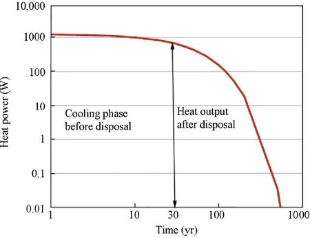
Fig.12.Evolution of the heat power of a vitrified waste container with time.
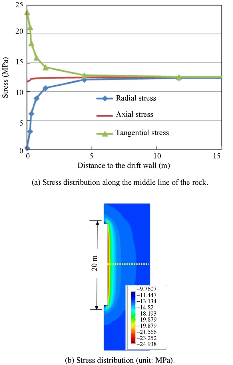
Fig.13.Stresses redistribution at the middle of the drift in rock after 2000 days.(a)Stress distribution along the middle line of the rock.(b)Stress distribution(unit:MPa).
4.Results and analysis
4.1.HM processes in the operation phase
Due to the excavation and ventilation of the disposal drift,the primary HM state of the surrounding rock is disturbed.After the excavation,the initial stress redistributes in the near area around the drift with a minimum radial component,a maximum tangential component,and a middle component in direction of the drift axis.Fig.13 shows the redistributed stresses in the clay rock around the drift as a function of the distance to the drift wall.Whereas the radial stress at the wall is zero,the tangential stress reaches 24MPa.In the far- field beyond the radius of 15m,the difference between the stress components tends to zero.
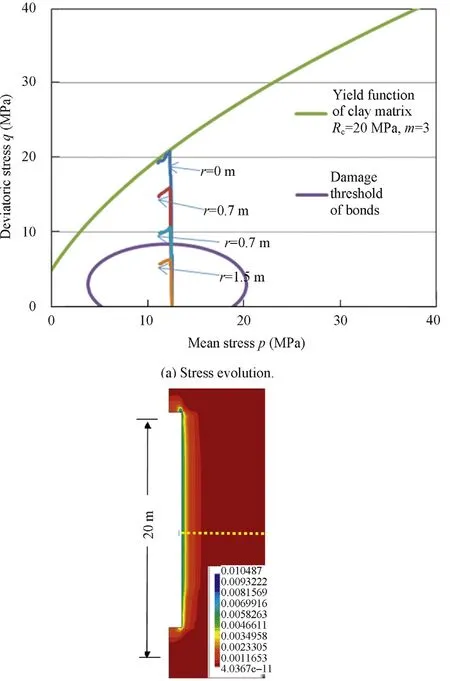
The deviatoric stresses are compared with the damage threshold of bonds and the yield boundary of clay matrix in Fig.14.One can see that the deviatoric stresses developed in the near- field within a radius of about 1m are beyond the damage locus.This means that the bonds in the clay rock are more or less destructured.Only at the drift wall the stress attains the yield curve,so that a plastic deformation may occur there.The damaged zone extends from the drift wall into the rock mass in a distance of about 1.5m(Fig.14b).
The stress changes lead to rock deformation towards the open drift.Fig.15 illustrates the evolution of radial displacements at different points in the clay rock.The displacement at the drift wall reaches the maximum of 9mm.At a distance of 25m to the drift wall,the radial displacement is nearly zero because the stress in the far- field is not significantly changed by the excavation.It is also interesting to note that the displacement at the drift wall keeps nearly constant.This indicates the ventilation effect.The clay rock shrinks on one hand and its stiffness increases with desaturation on the other hand,which prevent further convergence of the drift.
The drift excavation and ventilation also cause changes in the pore-water pressure.Fig.16 shows the resulting evolution and distribution of the pore-water.Under the relatively dry conditions in the drift during the ventilation,the pore-water pressure decreases with time due to the steady evaporation of the water.The negative pore-water pressure indicates a desaturation of the rock.Over 2000 days(5.5 years),the hydraulically perturbed zone is limited within 5m around the drift.
4.2.THM processes in rock-buffer-barriers
The heat emitting from the HLW containers is gradually transferred into the buffer and the rock,forming a temperature field with varying gradient.Fig.17 shows the time evolution of temperatures at some selected points in the buffer and the rock,while the temperature distributions at various times are illustrated in Fig.18.Immediately after the disposal of the containers,the temperature in the buffer rises very quickly.The maximum temperature of 157°C is achieved at the surface of the containers after 2.6 years of heating.After that,the temperature at the container surface tends to decrease slowly with time.At the interface between buffer and rock,the temperature reaches the maximum of 93°C after 4 years of heating and then decrease begins.Far away from the interface,the temperatures in the rock are lower than the conceptual criterion of 90°C.Over the first heating phase of 4.5 years,the heated area extends from the containers to about 15m into the rock mass.Based on the similar modelling results reported in OECD(2003),it can be expected that the temperature field will extend further into the rock.But due to the decay of heat output from the HLW containers,the critical temperature is not exceeded in the rock and a cooling down phase will follow.
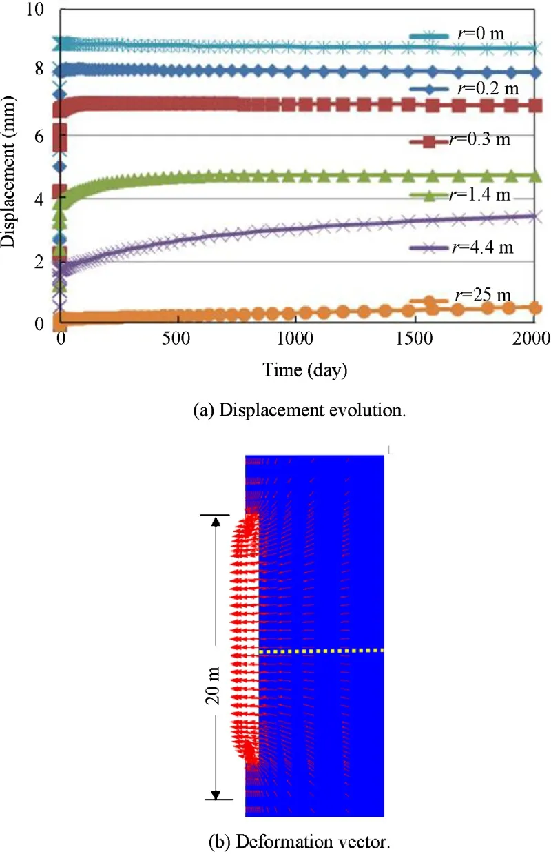
Fig.15.Evolution of radial displacement of the clay rock after drift excavation and displacement vector after the 2000 days ventilation.(a)Displacement evolution.(b)Deformation vector.
The most important hydraulic process in the buffer is the hydra tion of the very dry bentonite after back filling.In the clay rock with very low permeability,the most significant hydraulic process is the changes of pore-water pressure.Fig.19 shows the evolution of pore-water pressure at selected points along the middle section in the rock,while the pressure distributions at 1-3 years are depicted in Fig.20.Fig.19indicates that the drift excavation results in a sudden increase of the pore-water pressure up to 9MPa near the drift wall(r=0-0.2m).During the ventilation,the pore-water pressure falls down to negative values,indicating a desaturation process.The back fill of dry buffer causes a more desaturation in this near- field.In contrast to that,heating gives a rise of the porewater pressure in the saturated region(r>0.3m).Within the area of r<1.5m to the drift wall,the pore-water pressure increases to the maximum values of 3-7MPa during the first month and then decreases gradually with time.The increase in pore-water pressure is caused by the significant difference of the higher water expansion(3.4×10⁻⁴K-1)and the lower solid expansion(1.5×10⁻⁶K-1),whereas the gradual reduction of the pore pressure is due to the migration of the pore-water(vapour and liquid flow)towards the dry buffer.The increase rate of the pore pressure becomes slower in the far- field.The maximum pore pressure of 8.8MPa is reached at the distance of r=4.4m at 1 year.At distance r=11.3m,a lower peak pressure of about 7MPa is obtained.Fig.20 shows clearly that the over pressure zone extends with time from the near- field into the far- field but with decreased magnitude of the peak pressure.
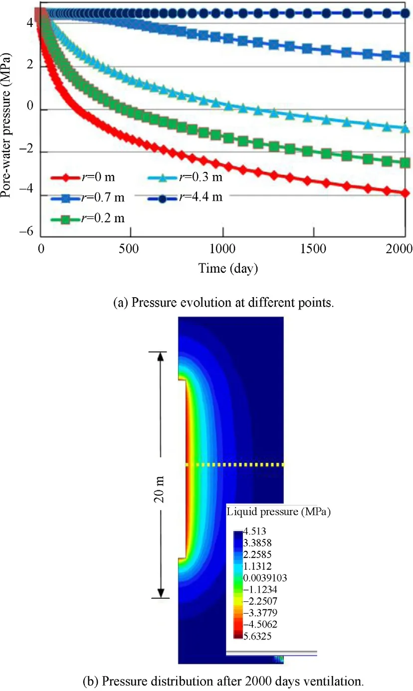
Fig.16.Evolution and distribution of pore-water pressure in the clay rock.(a)Pressure evolution at different points.(b)Pressure distribution after 2000 days ventilation.
The temperature increase and the hydraulical processes in the rock and the buffer have effects on the stress-strain behaviours of both materials,which also interact on each other.
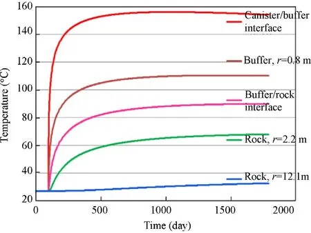
Fig.17.Evolution of temperatures at different points in the buffer-rock-barriers.
Fig.21 illustrates ther mally induced variations of the total radial stress in the clay rock.Due to the thermal expansion of the rock mass and the con fined load conditions,an excess stress builds up in the area near and beyond the heated region(comparing Figs.17 and 18).The high stress zone extends faster and is larger than the elevated temperature and pore pressure zones(comparing Figs.19 and 20).The maximum value of the total stress is about 16MPa(negative value indicating compression).Because the total
stress is still higher than the maximum pore pressure of approximately 9MPa,no hydraulic fracturing can take place.
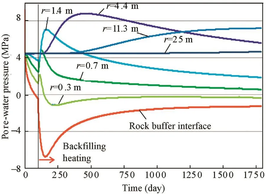
Fig.19.Evolution of pore-water pressure at selected points in the rock.
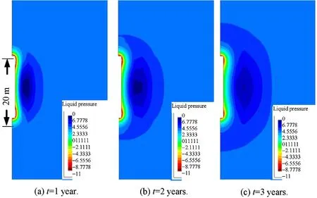
Fig.20.Distribution of pore-water pressure in the rock during the heating phase(unit:MPa).
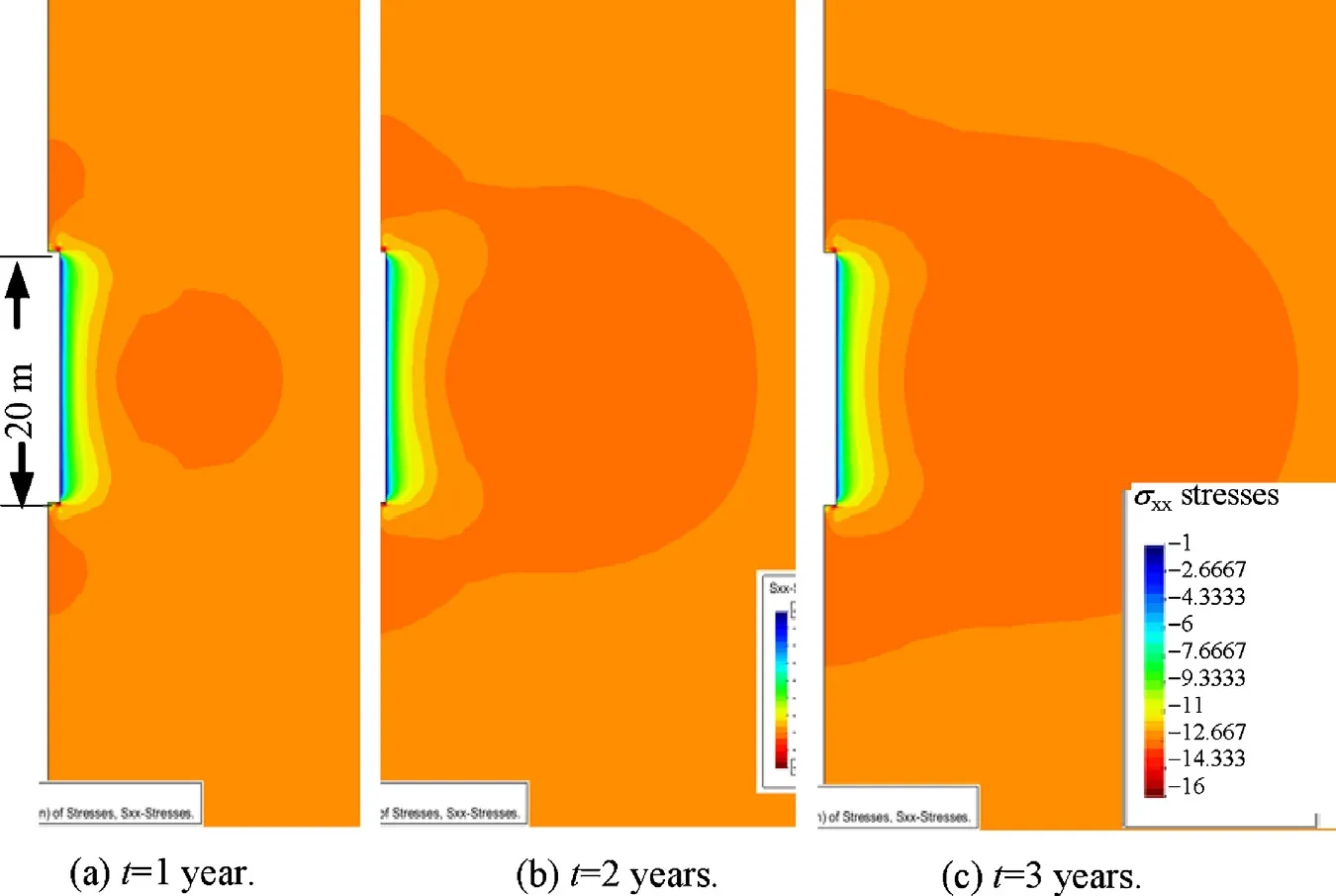
Fig.21.Distribution of total radial stress in the rock during the heating phase(unit:MPa).
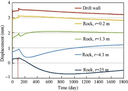
Fig.22.Evolution of radial displacements at different locations in the rock.
The variations of the THM conditions and the back fill resistance have impact on rock deformation.Fig.22 compares the displacements at different locations.The heating produces a short convergent deformation of the rock near the drift(r<0.2m).Because of the build-up of the back fill pressure,the deformation in this area turns back slowly.In the saturated far- field(r>1.1m),the temperature increase results in expansion in all directions,i.e.not only towards the back filled drift(positive increment)but also towards the rock depth(negative increment).Fig.23 shows the directions of the rock deformation at 3 years.The thermal expansive heart zone moves with time and seems to be coincident with that high pore-pressure zone(comparing Figs.19 and 20).
It is also interesting to examine the damage of the rock by comparing the stress states in the near- field with the damage locus and the yield boundary,as shown in Fig.24.It is obvious that the deviatoric stresses in the near- field within a radius of about 1m are beyond the damage locus,indicating that the bonds in the rock are more or less destructured.The deviatoric stress at the drift wall(r<0.2m) first rises immediately after the excavation and even exceeds the yield limit.A plastic deformation occurs there.After back filling,the deviatoric stress reduces gradually due to the backfi ll pressure against the rock.This prevents further development of the damaged zone and leads the rock to heal with time.
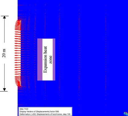
Fig.23.Rock expansion due to the thermal loading after 3 years.
5.Conclusio ns
Inspired by the French concept in 2005 for disposal of HLW waste and the in situ prevailing conditions data in the Bure URL,coupled THM processes occurring in the rock and the buffer during the drift excavation,ventilation,back filling and heating in unsaturated porous media have been simulated using the CODE BRIGHT.The models describe the HM processes during the excavation/ventilation operation and the THM processes after the back filling in the buffer and in the rock surrounding the HLW containers.Because of the limited capacity of the computer used,modelling results could be obtained only for the first 5 years of the disposal operation.The main conclusions drawn from the modelling study are summarized as follows:
Fig.24.Rock stress states compared with the damage and yield boundaries.
(1)The heat from the HLW containers transfers gradually into the buffer and the rock.The maximum temperature of 157°C is observed at the surface of the containers after about 2.5 years.The temperatures in the rock are limited below the conceptual criterion of 90°C,except for that of 93°C at the rock/buffer interface.
(2)Heating causes evaporation of the pore-water in the buffer near the containers and thus desaturation.In the opposite side,the water saturation in the buffer near the rock increases.
(3)The increase of temperature in the saturated rock generates a significant rise of the pore-water pressure up to 9MPa due to the very low porosity and the large difference of the water expansion and the solid expansion.Simultaneously,the total rock stress increases,too.Because the effective stresses during the heating phase are still compressive,no fracturing can take place during the heating period,which could be harmful for the long-term safety of the disposal.
(4)Although only a time period of 5 years of simulation has been completed due to the limit of the computation capacity and the high complexity of the processes,the calculated temperature has reached the maximum value at most area of the model,thus,the most probable critical processes for the disposal project have been represented.The simulation results are valuable to understand the THM process and its influence on the repository project.The work also provides an input for additional development in the design,assessment and validation of the HLW disposal concept.
Acknowledgements
The work described in this paper was financed and supported by the German research institute “Gesellschaft für Anlagen-und Reaktorsicherheit(GRS)mbH”.The valuable suggestions from the reviewers for this paper are also gratefully acknowledged.
ANDRA.Dossier 2005 argile:tome—architecture and management of a geological repository.Paris:ANDRA;2005a.
ANDRA.Dossier 2005 argile:synthesis—evaluation of the feasibility of a geological repository in an argillaceous formation.Paris:ANDRA;2005b.
CODE BRIGHT.A 3D program for thermo-hydro-mechanical analysis in geological media manual.Barcelona:UPC;2004.
Gens A,Garcia-Molina AJ,Olivella S,Alonso EE,Huertas F.Analysis of a full scale in situ test simulating repository conditions.International Journal for Numerical and Analytical Methods in Geomechanics 1998;22(7):515-48.
Gens A,Olivella S.Coupled thermo-Hydro-mechanical analysis of engineered barriers for high-level radioactive waste Chinese.Journal of Rock Mechanics and Engineering 2006;25(4):670-80.
Gens A,Vaunat J,Garitte B,Wileveau Y.In situ behaviour of a stiff layered clay subject to thermal loading:observations and interpretation.Géotechnique 2007;57(2):207-28.
IAEA.In:Report on radioactive waste disposal.Technical Reports Series No.349;1993.
OECD.Engineered barrier systems and the safety of deep geological repositories(state of the art report).OECD;2003.
Olivella S,Carrera J,Gens AA,Alonso EE.Nonisothermal multiphase flow of brine and gas through saline media.Transport in Porous Media 1994;15(3):271-93.
Vaunat J,Alonso EE,Gens A.Constitutive model of short and long term behaviour of the Meuse/Haute-Marne argillite.In:Deliverable 2&3 of the project MODEXREP,FIKW-CT2000-00029;2003.
Vaunat J,Gens A.Aspects of modelling geotechnical problems in hard soils and soft argillaceous rocks.In:Proceedings of the ninth international symposium on numerical models in geomechanics—NUMOG IX.Ottawa,Canada:Taylor&Francis;2004.p.37-43.
ZhangCL,RothfuchsT,MoogH,DittrichJ.Thermo-hydro-mechanicalandgeochemical behaviour of the Callovo-Oxfordian argillite and the Opalinus clay.GRS 2004;202.
ZhangCL,RothfuchsT,JockwerN,WieczorekK,DittrichJ,MüllerJ,HartwigL,Komischke M.Thermal effects on the Opalinus Clay-A Joint heating experiment of ANDRA and GRS at the Mont Terri URL(HE-D Project).Braunschweig.GRS 2007.
Zhang CL.Preliminary modeling of laboratory benchmark experiments performed by GRS in the frame work of the ECTIMODAZ project(personal communi cation).Braunschweig:Gesellschaft für Anlagen-und Reaktorsicherheit mbH;2009.
猜你喜欢
杂志排行
Journal of Rock Mechanics and Geotechnical Engineering的其它文章
- A comparative study on the application of various artificial neural networks to simultaneous prediction of rock fragmentation and backbreak
- Failure behavior of highly stressed rocks under quasi-static and intensive unloading conditions
- Numerical study on static and dynamic fracture evolution around rock cavities
- Shear strength criteria for rock,rock joints,rock fill and rock masses:Problems and some solutions