Low spurious noise frequencysynthesis based on a DDS-driven wideband PLL architecture
2013-11-05WANGHongyu王宏宇WANGHaofei王昊飞RENLixiang任丽香MAOErke毛二可
WANG Hong-yu(王宏宇), WANG Hao-fei(王昊飞), REN Li-xiang(任丽香),MAO Er-ke(毛二可)
(School of Information and Electronics,Beijing Institute of Technology,Beijing 100081,China)
Modern radar and communication systems have raised extremely demanding requirements for the synthesized frequency hopping time,bandwidth and noise levels.Direct digital synthesizer(DDS)has an absolute advantage in terms of frequency resolution and switching time.Nevertheless,as the maximum usable clock frequency of state-of-the-art commercial solutions is limited by 1GHz,it is not possible to act as a radar local oscillator directly in the desired RF band in most cases.Besides,although the output bandwidth of the DDS could be several hundred megahertz,its spurious performance in the wideband spectral range is far below the system requirement.These spurious components have been attributed to the bit width truncation of the phase accumulator[1-2],the sine waveform lookup ROM[3-4]and the digital to analog convertor (DAC)[5].At some output frequencies,the amplitude of these spurs is high enough to degrade the signal to noise ratio,which severely affects the DDS practical utilization in various synthesizers.
A straightforward solution for upconversion of the DDS output sweep is to use the DDS as a reference for a phase-locked loop (PLL)stabilized voltage-controlled oscillator(VCO)[6-7].However,the frequency switching time is then limited by the PLL lock-in process.Limited bandwidth causes a relatively long integration time of the loop filter.Meanwhile,high level close-in spurs of the DDS output will suffer from a gain of 20lgNby the PLL amplification.DDS output frequency,bandwidth and PLL characteristics must be carefully designed to achieve low spur level and fast switching in such a synthesizer[8-9].The subject of this paper is to investigate the role of fundamental frequency multiplexing in the generation of high amplitude spurious components.Furthermore,utilizing the proposed DDS frequency planning technique,a 4GHz synthesizer prototype based on DDS-driven wideband PLL is developed.The DDS is planned to generate 16MHz agile frequency signal.The 10MHz loop bandwidth PLL is designed to guarantee fast frequency switching.Simulated and measured results are analyzed to demonstrate the performance of high spurious free dynamic range(SFDR)and rapid frequency settling simultaneously.This synthesizer prototype is adopted in an S-band 320MHz stepped frequency radar to verify its practical overall performance.The measured results of the radar system present its spurious performance in wideband frequency output range.
1 DDS spurious components
A conventional block diagram of the DDS is shown in Fig.1.In order to save die area and power,the phase accumulator output is normally truncated,which means for the generation of the output sine wave,a small number of the most significant bits(MSB),L,are used.This truncation mechanism introduces a series of spurious component and degrades the spectral purity of DDS output spectra.

The DDS output frequency is
whereFis the frequency chosen word withN-bit width andfkis DDS system clock frequency.
The accumulator output repetition generates equally spaced spurious tones located at multiples of the frequency.The phase truncation process causes phase error periodic.If theL-bit MSBs of anN-bitFare employed to address the sine wave lookup ROM,the truncation resultant spurious tone inter-vals are

and ther-th order spurious component level is[1]

The truncation resultant spur levels could be lowered by extending bit width ofFand phase accumulator output.In practical systems,there is a tradeoff between the spur levels and device complexity.
Apart from the truncation resultant spurs,DAC images may introduce even higher spurs on DDS output frequency spectra.The worst case spurs occur whenever the images of the DAC harmonics fold back such that they are close to the DAC fundamental frequency.DAC images occur at

wherePandQare integer multiples offkandforespectively.
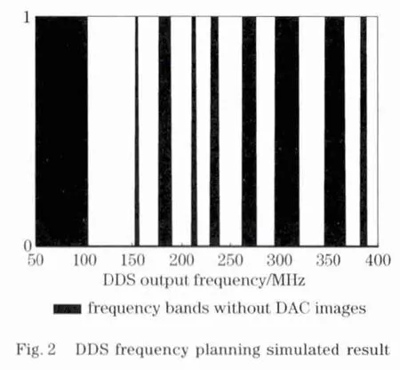
It is possible to produce the same desired frequencyfkby different combinations offoandF.In this case,the worst DAC spurs are placed well far from the carrier frequency and attenuated by a bandpass filter or equivalent circuits.For instance,if a 1 GHz system clock DDS is about to generate 16MHz bandwidth frequencies.Up to seventh harmonics of the carrier are taking into account.The simulated result is shown in Fig.2,in which ideal filter is used.It is obvious that only discrete frequency bands are suitable to achieve high SFDR.
2 DDS-driven wideband PLL architecture
Because of the spurious components dominating on DDS output spectra,practical utilization of DDS generation of frequency signals is limited to narrow frequency bands.In order to satisfy the requirement of modern wideband synthesizers,aproper frequency multiplexer must be employed to extend bandwidth.Howerer,the spurs and phase noise are gained up by 20lgNin theory,whereNis the gain of the frequency multiplexer.Meanwhile,a harmonic frequency multiplexer normally cooperates with high order bandpass filters to degrade phase linearity over wide bandwidth.
A PLL-based frequency multiplexer is also able to extend the bandwidth,meanwhile its VCO output is without the phase nonlinearity problem.Benefiting from the PLL loop filter,spurs outside the loop bandwidth can be attenuated.The loop attenuation rate of a second order PLL slightly outside the loop bandwidth is typically 20dB/decade,and the attenuation rate of a third order PLL is 40dB/decade.
A DDS-driven wideband PLL synthesizer architecture is shown in Fig.3,in which a third order type II PLL is designed to attenuate out-of-band spurious tones of the DDS output.

Fig.3 DDS-driven wideband PLL synthesizer architecture
In order to achieve rapid frequency hopping,the loop bandwidth of the PLL must be much wider than a conventional PLL employed in integer-Nor fractional-Nsynthesizers.
3 Synthesizer prototype and measured results
An S-band synthesizer prototype based on architecture shown in Fig.3is conducted to illustrate the effect of DDS frequency planning and wideband PLLs.This synthesizer performance is summarized in Tab.1.

Tab.1 Summary of synthesizer performance
The enhanced loop filter design is also shown in Fig.3.Two first order RC filters are added to the third order type II loop filter to suppress op-amp noise and synthesizer out of band noise.The input resistor is splitted into two of equal value of 500Ω,combined with a 100pF capacitor,then introducing a further pole into the transfer function with a corner frequency of about 50MHz.The extra thus introduced pole will degrade the phase margin of the loop filter by about 5°,which is in the permission range of the filter.The resistor above the op-amp is 33Ωin parallel with a 2pF capacitor,followed by a 4.7nF capacitor.The overall phase margin of this loop is set to about 60°to guarantee the loop stability.
A typical measured synthesizer output spectrum is shown in Fig.4,which presents no obvious spurious tone higher than-65dBc in a 1GHz span.
Spurious noise in wideband DDS output frequency band has long been the bottleneck of performance of digital synthesizers.Based on the DDS-driven wideband PLL architecture and proposed frequency planning method,the spurious noise is able to be alleviated effectively.Fig.5presents measured results of wideband SFDR under the condition of with and without frequency planning,in which a 22times and a 20times PLLs are used respectively.If a carefully chosen DDS output frequency band is employed to drive a PLL,the overall SFDR is better than 60dBc.Nevertheless,the DDS output may partially suffer from DAC images-induced spurious components if the DDS output frequency and bandwidth are selected randomly.

In order to verify its practical overall performance,the synthesizer is adopted in an S-band 320 MHz stepped frequency radar.The synthesizer is rapidly switched among 64frequencies with 5MHz step,with 0.3μs settling time.Figs.6-7illustrate measured coherent processing results of the radar.In Fig.6,the measured results presents high spurs on some frequency points.In contrast,if frequency planning approach is utilized properly,the processed results present no obvious high level spurs,as shown in Fig.7.

4 Conclusion
Mechanisms of producing spurs in DDS are comprehensively analyzed.A proposed frequency planning method,by proper combination of system clock and output frequency,is capable of choosing a relatively narrow DDS output frequency band with low level spurious tones.This method allows utilizing exist DDS technique to generate cleaner frequency signals.Because of the DDS characteristic of low output frequency and narrow bandwidth,a PLL-based frequency multiplexer is suitable to multiply DDS output frequency signals to radio or microwave frequencies.
An S-band frequency synthesizer prototype isdeveloped.Taking into account of the frequency switching speed,the loop bandwidth is designed to about 10MHz.Measured results illustrate the average SFDR of this synthesizer in 320MHz bandwidth is about 64dBc,the worst case is 59dBc and the frequency switching time is within 1μs,which can satisfy the critical requirements of most radar and wireless communication systems.
[1] Kroupa V F,Cizek V,Stursa J,et al.Spurious signals in direct digital frequency synthesizers due to the phase truncation[J].IEEE Transactions on Ultrasonics,Ferroelectrics and Frequency Control,2000,47(5):1166-1172.
[2] Salomon M E,Izouggaghen B,Khouas A,et al.Spur model for a fixed-frequency signal subject to periodic jitter[J].IEEE Transactions on Instrumentation and Measurement,2008,57(10):2320-2328.
[3] Strollo A G M,Caro D,Petra N.A 630MHz,76mW direct digital frequency synthesizer using enhanced ROM compression technique[J].IEEE Journal of Solid-State Circuits,2007,42(2):350-360.
[4] Caro D,Strollo A G M.High-performance direct digital frequency synthesizers using piecewise-polynomial approximation[J].IEEE Transactions on Circuits and Sys-tems I:Regular Papers,2005,52(2):324-337.
[5] Zhou Z H,Rue G S.A 12-bit nonlinear DAC for direct digital frequency synthesis[J].IEEE Transactions on Circuits and Systems I:Regular Papers,2008,55(9):2459-2468.
[6] Avitabile G,Cannone F,Vania A.Phase shifter based on DDS-driven offset-PLL[J].Electronics Letters,2006,42(25):1438-1439.
[7] Jaehung C,Minsu K,Seungha S,et al.Low phase noise S-band PLL frequency synthesizer using DDS and offset mixing techniques[C]∥Asia Pacific Microwave Conference.Piscataway,NJ,USA:IEEE,2009:1409-1412.
[8] Huang Chao,Ren Lixiang,Mao Erke.High-FM-linearity wideband chirp generator[J].Journal of Beijing Institute of Technology,2011,20(4):540-545.
[9] Zhai Longjun,Jiang Yonghua,Ling Xiang,et al.DDS-driven PLL frequency synthesizer for X-band radar signal simulation[C]∥First International Symposium on Systems and Control in Aerospace and Astronautics.Piscataway,NJ,USA:IEEE,2006:344-346.
杂志排行

Journal of Beijing Institute of Technology的其它文章
- Design and studyon variable nozzle mixed-flow turbocharger
- Numerical studyon the shock responses of submunition dropon various mediums
- Design,analysis and control for an antarctic modular manipulator
- Fuzzycontrol method to minimize the needle deflection duringneedle insertion therapy
- Simulation of multiphase boost DC-DC converter with the stable control strategy
- Acylation of 3,4-Diaminofurazan