Roll angle measurement system based oni triaxial magneto-resistive sensor*
2013-11-01ZHAOXinlu赵鑫炉ZHANGXiaoming张晓明
ZHAO Xin-lu(赵鑫炉), ZHANG Xiao-ming(张晓明),2
(1. Science and Technology on Electronic Test & Measurement Laboratory, North University of China, Taiyuan 030051, China;2. Key Laboratory of Instrumentation Science & Dynamic Measurement (North University of China),Ministry of Education, Taiyuan 030051, China)
Roll angle measurement system based oni triaxial magneto-resistive sensor*
ZHAO Xin-lu(赵鑫炉)1, ZHANG Xiao-ming(张晓明)1,2
(1. Science and Technology on Electronic Test & Measurement Laboratory, North University of China, Taiyuan 030051, China;2. Key Laboratory of Instrumentation Science & Dynamic Measurement (North University of China),Ministry of Education, Taiyuan 030051, China)
Aiming at large error when inertial devices measure the roll angle under high overload conditions, the article designs one kind of roll angle measurement system based on magneto-resistive sensor which calculates the roll angle by micro controller STM32. Experiment results of a triaxial turntable show that using magneto-resistive sensor to measure roll angle is feasible and of high accuracy, and it can calculate the roll angle of the conventional projectile with the error in 1°.
magneto-resistive sensor; roll angle; error
Roll information is of great significance for the spinning projectile's guidance and control. There are many methods for measuring the roll angle of spinning projectile both at home and abroad, for example, global position system (GPS), the telemetery of solar direction, acceleration, and so on. But the cost is too expensive, or attitude information cannot be accurately measured. In many circumstances, strap-down inertial measurement device in measuring projectile attitude will come across the problems of high range, high cost and large volume, etc., which make some limitations to the application of missile attitude measurement. Because geomagnetic sensor has high precision, large measuring range, small volume, low cost and real-time sensing to geomagnetic information, it can realize the projectile's roll angle measurement better. In this paper, according to the measurement principle of a triaxial magnetic sensor for roll angle, roll angle measurement system controlled by STM32 is designed via real-time calculating, which has higher accuracy and no accumulated error.
1 Roll angle calculation principle
The roll angle calculation principle of the system is put forward based on launch coordinate system and projectile coordinate system, as shown in Fig.1. Launching coordinate system is o-xnynzn, and body coordinate system is o-xbybzb. The carrier turns around z,y and x separately, and does the yaw angle, pitch angle and roll angle motions from o-xnynznto o-xbybzb. The yaw angle φ, pitch angle θ and roll angle γ describe three Euler angles of the attitude angles.

Fig.1 Carrier coordinate and launch coordinate systems
The transformation matrix between the coordinates o-xnynznand o-xbybzbis
Cbn=CzCyCx,
(1)
Suppose three-axis magnetic field component of launch coordinate system is
Hn=(HnxHnyHnz)T.
(2)
After the projectile rotation of three attitudes, a three-axis magnetic field component of body corrdinate system is
Hb=(HbxHbyHbz).
(3)
The result can be rewritten as
(4)
From the mathematical form, Eqs.(1)-(4) are linear correlation. It cannot calculate all of yaw angle, pitch angle and roll angle, so we need to know either of them, which can calculate the attitude angle of the other two attitude angles. This paper makes an approximation, because in the process of projectile spin, the yaw angle changes in a small-scale. By approximating the yaw angle as a fixed value, pitch angle and roll angle are solved. The type is simplified as
Hbx=(Hnxcosφ+Hnysinφ)cosθ-Hnzsinθ,
(5)
and θ and γ are got by
(6)
(7)
In Eq.(7),
b=Hnxcosφsinθ+Hnysinφsinθ+Hnzcosθ,
(8)
c=Hnycosφ-Hnxsinφ.
(9)
However, for the launch coordinate system, yaw angle can be set to 0. In this algorithm, only if we know three-axis magnetic field component of the launch coordinate system and the time of body rotation, the roll angle of the projectile can be calculated. Three-axis magnetic field component in launch coordinate system is initially preloaded, three-axis magnetic field component of the body coordinate system is obtained by fixed magneto-resistive sensor with carrier when the body attitude changes.
2 Hardware design
2.1 Measurement system
Roll angle measurement system is shown in Fig.2. The measurement system mainly consists of a microcontroller and a reset control module.
After the magnetic sensor real-time response to magnetic field information, for the sensor, the output is an analog voltage value, and the output signal of the magnetic sensors is millivolt level, which is very weak and needs to be amplified. The output signal of the magneto-resistive sensor can effectively recuperate for A/D convertor. Then microcontroller transforms the analog signal into digital signal, compensates the magnetic field and calculates roll angle in real-time. Finally, roll angle information is transmitted with universal synchronous/asynchronous receiver/transmitter (USART) and is stored in memory.

Fig.2 Block diagram of roll angle measurement system
2.1.1 Microcontroller
The core microcontroller STM32F415 is a high performance microcontroller based on Cortex-M4 kernel of ST corporation, of which one side does not require external A/D convertor. It has integrated three 12-bit A/D modules, and its resolution and conversion rate meet the measurement requirements, thus the cost and volume of hardware system are great reduced. On the other hand, it is developed based on the library, so the difficulty of development is lowered compared with the other control chip and the development cycle is shortened. The main advantage is that STM32 has a floating-point operation function, which can calculate the roll angle in real-time.
2.1.2 Reset circuit on magneto-resistive sensor
For an anisotropic magneto-resistive sensor HMC1043 of the system, its long-term exposure to a strong magnetic field results in lower sensitivity and calculation accuracy of roll angle, so the reset operation periodically not only ensures normal work, but also can keep its sensitivity with linear characteristics and improve the solution precision the system. Reset circuit for the sensor consists of C1, C2, R15, R16, Q1 and DO1, as shown in Fig.3. DO1 inputs periodic square wave pulse signal provided by the microcontroller STM32. When DO1 is low, the PNP triode Q1 is off and VCC charges the C1 through R15; When DO1 is high, C2 and R16 will generate a positive voltage, which makes Q1 be on and C1 discharges. Port SR+ will produce a voltage approximating to VCC and produce a 400 mA pulse current between SR+ and SR-. To obtain the current needed for the duration of the sensor reset, resistance R16 is charged with 220 Ω, and capacitor C1 is charged with 0.22 μF.
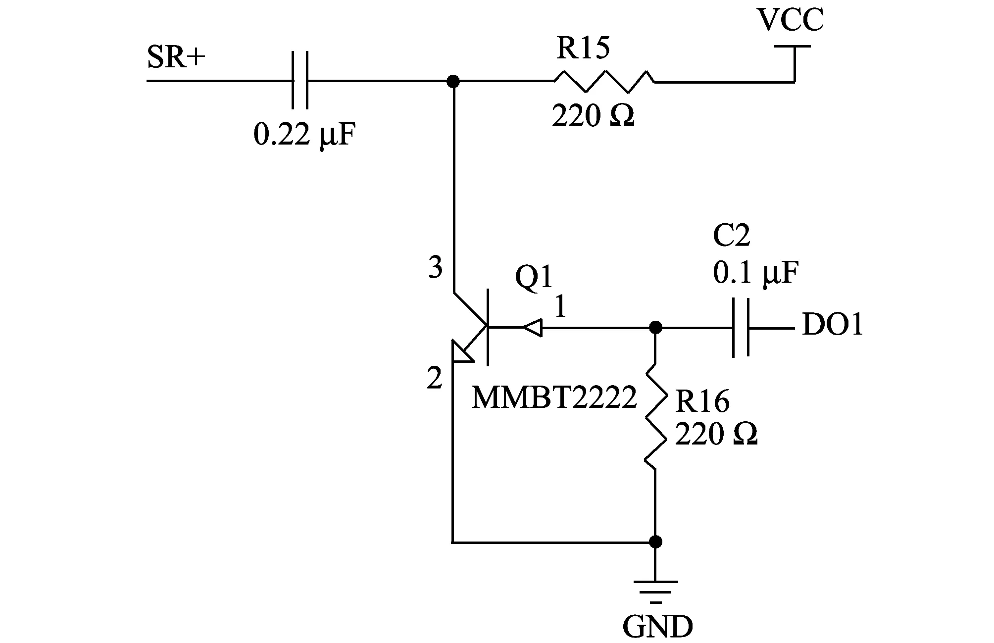
Fig.3 Schematic of magnetic sensor reset circuit
2.2 Analysis of experimental results
In order to verify the feasibility and precision of magneto-resistive sensor which calculates roll angle, another three-axis rate table is used, as shown in Fig.4. By simulating the application environment of the conventional spinning projectile, the precision of roll angle is verified by the difference between the roll angle information and the base roll angle.

Fig.4 A three-axis turntable
Setting three-axis feedback information of turntable as a criterion signal, the experiment simulates the onboard environment of the projectile in which the yaw angle and pitch angle are 0°. In the zero position of turntable (the inside frame, the medium frame, the outside frame are 0°), we preload initial three-axis magnetic field, initial angle of the roll angle 0°, roll rate 360 °/s and experimental time 10 s. Three-axis magnetic signal is shown in Fig.5 when rotating the inner frame. According to the three-axis magnetic signal, the roll angle is calculated in real-time, which is shown in Fig.6.

Fig.5 Three-axis magnetic signal
It can be seen from Fig.5, the Y-axis and Z-axis profiles of geomagnetic signals are sinusoidal ones, which accord with axial magnetic field variation rule of Y axis and Z axis of missile-borne environment. X axis signals appear with obvious fluctuation mainly because X axis of the turntable and X axis of the three-axis magneto-resistive sensor are not parallel to rate table. The measured geomagnetic signal also shows sinusoidal variation.
Experimental results show that the method by using magneto-resistive sensor to calculate roll angle is feasible, which can reflect the change of carrier attitude.
By comparing the solution of roll angle with the feedback signal simulator, difference is worked out. Roll angle error curve is shown in Fig.7. It can be seen that the error presents periodic variation and maintains at 1°, and the main frequencies are 1 Hz and 2 Hz according to the spectrum analysis of the error signal. The main reason is the inner frame on both sides by the interference of magnetic material.

Fig.7 Error of roll angle
3 Conclusion
This paper designs a measurement system based on geomagnetic field information. By pre-loading triaxial magnetic field component in launch coordinate system, roll angle is calculated in real-time when attitude changes under missile-borne environment. The experimental results show that the method of measuring the roll angle is feasible, and error is always in a reasonable range and not accumulated with time.
[1] MA Guo-liang, LI Yan, GE Jing-fei. Principle analysis for roll attitude measurement of spinning projectile using magnetic resistance sensor. Journa1 of Ballistics, 2012, 24(3): 33-36.
[2] SHI Guo-xing, YANG Shu-xing, SU Zhong. The study on attitude algorithm of rolling projectile using geomagnetic informaticon. Journal of Projectiles Rockets Missiles and Guidance, 2011, 31(5): 32-36.
[3] SHI Lian-yan. Design of roll angle measuring system of rocket body based on geomanetism measurement. Electronic Design Engineering, 2009, 17(3): 3-6.
[4] LI Xing-cheng, NIU Hong-yu. Research on attitude measuring of rolling missile based on magneto-resistive sensor. Computer Simulation, 2003, 29(5): 51-55.
date: 2013-03-02
National Natural Science Foundation of China (No.61004127)
ZHAO Xin-lu (zhaoxilu33@163.com)
CLD number: TP212.1 Document code: A
1674-8042(2013)03-0214-04
10.3969/j.issn.1674-8042.2013.03.003
猜你喜欢
杂志排行

Journal of Measurement Science and Instrumentation的其它文章
- Test on oxygen and benzene contents in gasoline by mid-infrared spectroscopy*
- Particle-filter-based walking prediction model for occlusion situations*
- Automatic estimation and removal of noise on digital image*
- Application of signal sparse decomposition in dynamic test*
- Kravchenko probability weight functions in problems of radar signals correlation processing*
- AC current automatic calibration using two different TCC designs*