Research on Key Technologies of Detecting 1553B Avionics Data Bus Network
2013-07-25DnqingCHENGuohuCAOJinghuWANGHuilinFAN
Dn-qing CHEN*,Guo-hu CAO,Jing-hu WANG,Hui-lin FAN
Research on Key Technologies of Detecting 1553B Avionics Data Bus Network
Dan-qiang CHENa,b,*,Guo-hua CAOa,Jing-hua WANGb,Hui-lin FANb
aCollege of Mechanical and Electronic Engineering,Changchun University of Science and Technology,Changchun 130022,Jilin,ChinabAviation University of Air Force,Changchun 130022,Jilin,China
1553B avionics data bus network may fail due to vibration,temperature,humidity or human error.Therefore,the research on detection technology of 1553B avionics data bus network is an important subject.The key technologies are studied by analyzing the possible faults of the network,including four-wire DC resistance measurement method for conductors-to-shield short test and stub continuity test,equivalent impedance measurement of coupling transformer for main bus continuity test,polarity reversal test base on duty ratio measurement,attenuation measurement base on coupler model,and data path integrity test base on bit error rate calculation.Finally,the implementation methods of key technologies are researched,a portable integrated automatic test system of 1553B data bus network is constructed based on PC104 computer,and the hardware conf i guration and test process are especially designed.
CopyrightⒸ2013,China Ordnance Society.Production and hosting by Elsevier B.V.All rights reserved.
Mil-Std-1553B Data bus network;Automatic test system;Fault location;Main bus;Stub;Coupler
1.Introduction
The MIL-STD-1553B data bus was initially designed for aircraft.With the improvement of informatization level of military equipment,the MIL-STD-1553B data bus has been widely applied in various f i elds,especially in aerospace and military applications[1].
The MIL-STD-1553B data bus system is composed of data bus network and terminals.It has been used in communication and data transmission betweenavionics navigation system,task management system and weapon system.It uses a half duplex data transmission with 1 Mb/s data rate in Manchester II code over twisted shielded pair(TSP)cable of which characteristic impedance is around 78 Ω.The data bus network includes main bus,stubs,couplers and termination resistors.The data bus network has the capability of connecting 31 terminals through the stubs.Three types of terminals including bus controller (BC),bus monitor(BM)and remote terminal(RT)are connected to the data bus network in either direct coupling method or transformer coupling method,as shown in Fig.1.Only the transformer coupling method is required for airborne applications because it allows longer branches with high reliability.In Fig.1,Z0isusedtorepresentthecharacteristicimpedanceofthe cable,R1andR2aretheisolationresistancesofthecoupler,R0is the load resistance of the terminal.The turns ratio N2:N1of coupling transformer is 1.41:1 with the higher number of turns on the side of isolation resistor.
2.Test requirements
The terminals or network may fail after the installation of 1553B avionics data bus system because of vibration,temperature,humidity or improper operation.The faults are generally considered to be caused by the electronics and software,but the network has proved to be the root of the faults.The common faults of the network include
(1)main bus or stub conductor-to-shield short;
(2)open or short.of stub conductors;
(3)short or open of main bus conductors,and wrong resistance of termination resistor;
(4)polarity reversal of conductor of stub or main bus;
(5)high insertion losses between stubs;
(6)high bit error rate of data paths.
How to test and evaluate the network characteristics roundly and availably is an important subject if the network fails.Faults should be detected from the stub because it’s impossible to disassemble the data bus network after its installation in an aircraft.The key technologies of detection and the implementation methods will be researched in this paper.
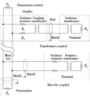
Fig.1.Composition and connection of 1553B data bus system.
3.Key technologies of detection
3.1.Four-wire DC resistance measurement method
DC resistance measurement is used for conductor-to-shield short test and stub continuity test.
In TSP cable the conductor-to-shield short might lead to a high data error rate[2].Therefore the conductor-to-shield short should be detected.The conductor-to-shield short test is basically to measure a DC insulation resistance.The standard DC insulation resistance between shield and conductor must be more than 5000 Ω without short.If the resistance between any conductor and shield is less than 50 000 Ω,it is considered as short.
The DC resistance of the transformer winding between high and low conductors of the stub is between 1.0 Ω and 5.0 Ω.If the DC resistance of the stub is below 1 Ω,it is interpreted as stub short.If the resistance is above 5 Ω,it is interpreted as stub open.If the resistance is 1.0-5.0 Ω,it is interpreted as normal condition.
The four-wire resistance measurement method is used to measure DC resistance,which is also called voltage-voltage method.The measurement principle is shown in Fig.2.
Uiis the voltage of DC source.Uxand Usare the voltages of resistor Rxunder measurement and known standard resistor Rs,respectively.The voltages Uiand Usare amplif i ed and converted to the digital values by AD conversion.The current I in the circuit is

3.2.Equivalent impedance measurement of coupling transformer
Equivalent impedance measurement of coupling transformer is to test main bus continuity,checking for the shorts or opens of the main bus conductors and the wrong termination resistor from a stub.Only two types of terminators(78 Ω and 3000 Ω)are in the network.The 78 Ω terminator is the right termination resistor on the main bus.
The coupler is connected to the terminators Z1and Z2through the main bus,and connected to the terminals through the stubs.A simplif i ed model of the coupler is shown in Fig.3. The signal is transmitted from the terminal on the stub to the main bus through the coupling transformer in the coupler.The turns ratio of the transformer is N2:N1.
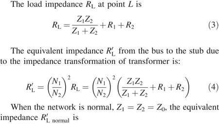
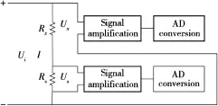
Fig.2.Principle of four-wire method.

Fig.3.Simplif i ed model of coupler.
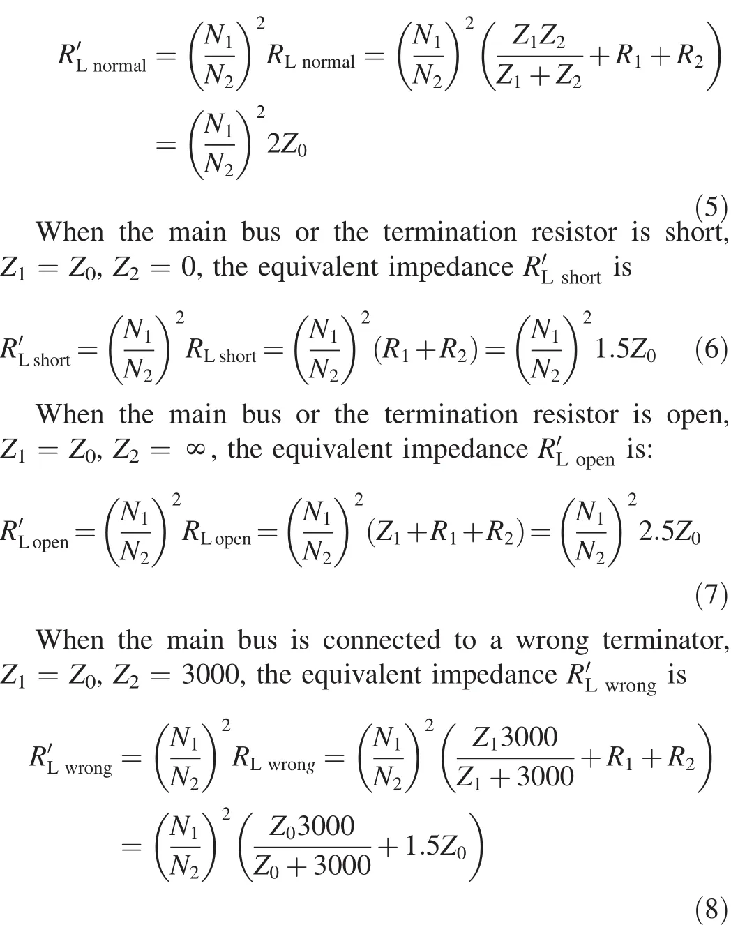
The communication protocol of MIL-STD-1553B states that Z0is 70-85 Ω[3].The values of R'Lin different conditions change as Z0changes from 70 Ω to 85 Ω,as shown in Fig.4.If the value of R'Lis between 70 Ω and 85 Ω,the main bus is normal;if it is below 65 Ω,the main bus conductors are short;and if it is above 87 Ω,the main bus conductors are open,or the main bus is connected to a wrong terminator.

Fig.4.RLvalues in different conditions.
3.3.Polarity reversal test base on duty ratio measurement
Duty ratio measurement can be used to check the polarity reversals of the main bus and the stubs.A signal receiver and a signal generator are used in the test.The generator is connected to one stub and emits 500 kHz pulse with duty ratio of 3/4.The receiver is connected to another stub for receiving the pulse.The duty ratios of pulses are different when the polarity of conductor is normal or reversal.In an ideal condition,the duty ratio of emitted pulse is 3/4,the duty ratio of received pulse is 3/4 in the case of normal polarity or 1/4 in the case of polarity reversal,as shown in Fig.5.
It can be determined through test whether the polarities of conductors connecting the signal generator and receiver with the network are normal or reversal.If the duty ratio of the received pulse is below 1/2,the polarities of the conductors are reversal;it is above 1/2,they are normal.
If any failure is detected in polarity reversal test,it is necessary tof i ndoutwhich part ofthe mainbus andwhichstubs are involved in the failure problem.The f i rst step is to connect the generator to any stub and emit the pulses.The receiver is connected to the next stub for polarity reversal test.If the receiver indicates“test pass”,then the polarities on both stubs and the main bus between them are normal.If the receiver indicates“test fail”in oneor few stub locations with respect to the generator,the polarity reversal is on those stubs where the receiver shows“fail”indication.If the receiver indicates“test fail”on all the stubs with respect to the generator,then the polarity reversal is on the stub which thegenerator is connected to.
3.4.Attenuation measurement base on coupler model
The attenuation measurement is used to test the insertion losses between two stubs.A signal receiver and a signal generator are used in the attenuation measurement.The attenuation is the ratio of the voltage emitted on one stub to the voltage received on another stub.The attenuation is measured with 1 MHz sine wave.
A simplif i ed coupler model is used to measure the attenuation in the network.The coupler model is divided into two categories.The f i rst model is to suppose that the signal generator connected to the coupler transmits a signal,asshown in Fig.6.The second model covers the case where the signal receiver receives a signal,as shown in Fig.7.
When the signal generator transmits a signal,the voltage ratio is

Fig.6.Simplif i ed coupler model for the signal generator transmitting signal.
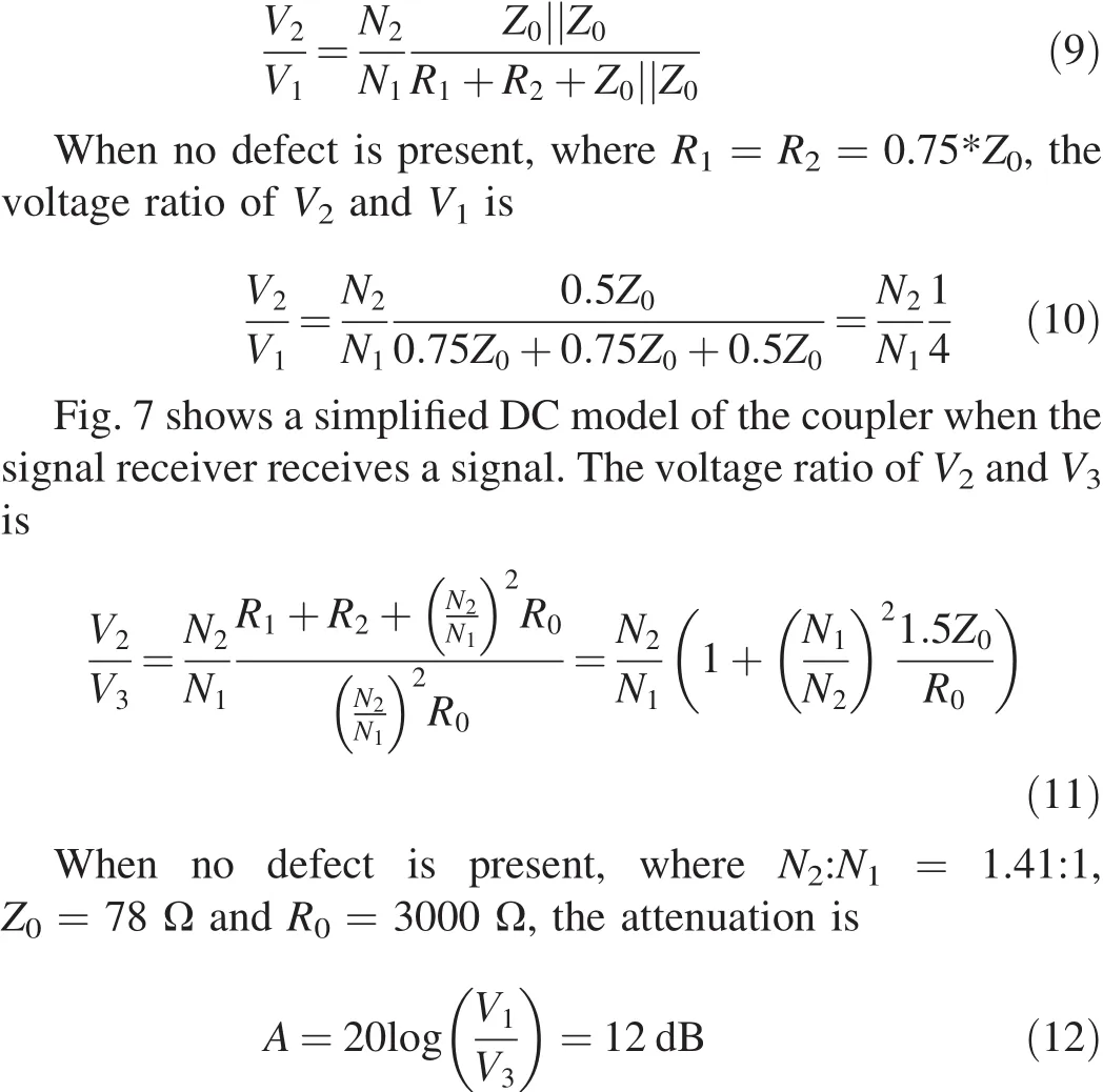
Based on the simplif i ed coupler model,the attenuation between any two stubs is 12 dB in a perfect network.However, in practice,the connectors and cables of the network have the insertion loss,so the attenuation varies from 12 dB to 17 dB and depends on the network conf i guration since the cables have a specif i ed loss of 0.0492 dB/m[4].The number of stubs in the network and the lengths of the main bus and stub should be considered in the attenuation measurement.
3.5.Integrity test of data path base on bit error rate
calculation
This integrity test of data path is to check the working condition of Mil-Std-1553B data bus network by calculating bit error rate.All possible paths from BC to RT are combined in the network.Each path should be tested for 10,000 times of data receiving and transmitting test in both directions between stubs.32 data words should be contained in each test,which are random numbers in 1553B format.The network passes the integrity test only when the bit error rate is zero[5].

Fig.7.Simplif i ed coupler model for the signal receiver receiving signal.
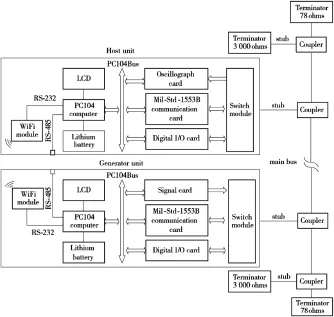
Fig.8.Host unit and generator unit in test.
4.Design of automatic test system
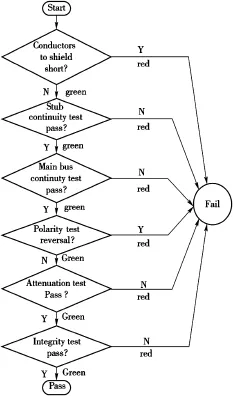
Fig.9.Test process.
The most important work is to research the implementation methods of key technologies to design an automatic test system(ATS)for 1553B data bus network.
The traditional manual detection of 1553B data bus network needs a lot of instruments,including ohmmeter, continuity tester,signal generator,oscillograph and time domain ref l ectometry(TDR).As all the instruments are connected to every stub,the test process is complex,diff i cult,andtime-consuming.The human factors have a signif i cant effect on the test results,which leads to poor test consistency.
The operators have to face the problems of narrow test space and the impossibility of disassembling the network from the aircraft in on-site detection.Therefore,a portable,easy-tooperation,integrated test system is required for the network. In the design of ATS for 1553B data bus network,the most important issues are hardware conf i guration design and test process design.

Table 1Test result of 1553B data bus network.
4.1.Hardware conf i guration design
ATS is used to check whether the 1553B data bus network operates properly,detect the possible failures,and locate the faults.A signal generator and a signal receiver are used in polarity reversal,attenuation and integrity tests.The 1553B data busnetworkATSisdividedintohostunitandgeneratorunit.The generatorunitisconnectedtoonestubandthehostunitismoved from one stub to another stub during testing,as shown in Fig.8.
The host unit and generator unit are constructed based on a PC104 computer operating on Windows XP,an 8 in.touch screen and 27 V lithium battery.Both the units communicate through WiFi or RS-485 to perform all tests.
In the host unit,an oscillograph card with a sampling rate of 1 GSa/s is used for measuring resistance and voltage and analyzing the signal waveforms in detail;a Mil-Std-1553B communication card is used to simulate RT for receiving 1553B data words in integrality test.
In the generator unit,a 40 MHz signal card is used to generate the excitation signals;a Mil-Std-1553B communication card is used to simulate BC for transmitting 1553B data words in integrality test.
The test data is displayed on the screen of host unit.The virtual light indicates the test results,the green light indicated“Pass”,and the red light indicates“Failed”.The test data and results can be printed and registered through USB interface. 4.2.Test process design
Thehostunitisusedfortheshortdetectionofconductorsand shield,the continuity test of stub and the continuity test of main bus.Both host unit and generator unit are used for polarity reversal test,attenuation measurement and integrality test.The test sequence in Fig.9 should be followed during detection.
It is important to perform the test in sequence.The subsequent items under detection can be detected only after a failed item is repaired so that the effect of failed item on the subsequent items under detection is avoided.
5.Conclusions
1553B data bus network ATS was used to detect 1553B data bus network of some type aircraft.The results from ATS are compared with the results from S2476N data bus network tester made by BCF Designs Ltd in England.The test results are listed in Table 1.
Compared to S2476N data bus network tester,1553B data bus network ATS has an integrity test function.ATS not only shows test result,but also shows test data and has higher accuracy in measuring attenuation.If faults occur in the data bus network,the 1553B data bus network ATS can pinpoint the cause and location of a failure.
The key technologies of detecting avionics 1553B data bus network from the stubs were discussed,with emphasis on the hardware conf i guration and test process in designing a portable automatic test system based on PC104 computer.
The application showed that the 1553B data bus network ATS can detect the network roundly,and locate any fault with a very high level of conf i dence in a short time.The test process is carried out automatically,the test reports are displayed clearly and unambiguously,and the detection eff i ciency and reliability are improved greatly.
Acknowledgements
This paper is supported by the Key Equipment Research Project of Air Force of China(KJ2011215).
[1]Zhi CY.Avionics data bus technology and its applications.Beijing:National Defense Industry Press;2009.p.237-42[in Chinese].
[2]Smith P,Furse C,Gunther J.Analysis of spread spectrum time domainref l ectometryforwirefaultlocation.IEEESensJ 2005;5(6):1469-78.
[3]Data Device Corporation.Mil-Std-1553 designer’s guide.6th ed.;2003. II-9.
[4]Furse C,Chung YC,Lo C.A critical comparison of ref l ectometry methods for location of wiring faults.Journal of Smart Structures and Systems 2006;2(1):25-46.
[5]GJB5186-2004.Digital time division command/response multiplex data bus test plan.Beijing:Commission of Science,Technology and Industry for National Defense;2004[in Chinese].
y ratio of
pulse.
Received 18 January 2013;revised 16 July 2013;accepted 20 July 2013 Available online 5 October 2013
*Corresponding author.College of Mechanical and Electronic Engineering, Changchun University of Science and Technology,Changchun 130022,Jilin, China.
E-mail address:chendanqiang@sina.com(D.Q.CHEN).
Peer review under responsibility of China Ordnance Society
Production and hosting by Elsevier
2214-9147/$-see front matter CopyrightⒸ2013,China Ordnance Society.Production and hosting by Elsevier B.V.All rights reserved.
http://dx.doi.org/10.1016/j.dt.2013.09.019
杂志排行
Defence Technology的其它文章
- The Research on Compressive Properties of Polytetraf l uoroethylene at High Strain Rate
- Application of Space-time Conservation Element and Solution Element Method in Intake and Exhaust Flows of High Power Density Diesel Engine
- Research on Optical Properties and Micro-processing Characteristics of Collodion Thin Film
- The Spatial Color Mixing Model of Digital Camouf l age Pattern
- Design Method of Equipment Optimization Development Based on Standardization Theory
- First-principles Study of Electronic Structures,Elastic Properties and Thermodynamics of the Binary Intermetallics in Mg-Zn-Re-Zr Alloy
