Three-dimensional large eddy simulation and vorticity analysis of unsteady cavitating flow around a twisted hydrofoil*
2013-06-01JIBin季斌LUOXianwu罗先武
JI Bin (季斌), LUO Xian-wu (罗先武),
State Key Laboratory of Hydroscience and Engineering, Tsinghua University, Beijing 100084, China, E-mail: jibin@mail.tsinghua.edu.cn
PENG Xiao-xing (彭晓星)
China Ship Scientific Research Center, Wuxi 214082, China
WU Yu-lin (吴玉林)
State Key Laboratory of Hydroscience and Engineering, Tsinghua University, Beijing 100084, China
Three-dimensional large eddy simulation and vorticity analysis of unsteady cavitating flow around a twisted hydrofoil*
JI Bin (季斌), LUO Xian-wu (罗先武),
State Key Laboratory of Hydroscience and Engineering, Tsinghua University, Beijing 100084, China, E-mail: jibin@mail.tsinghua.edu.cn
PENG Xiao-xing (彭晓星)
China Ship Scientific Research Center, Wuxi 214082, China
WU Yu-lin (吴玉林)
State Key Laboratory of Hydroscience and Engineering, Tsinghua University, Beijing 100084, China
(Received November 19, 2012, Revised February 28, 2013)
Large Eddy Simulation (LES) was coupled with a mass transfer cavitation model to predict unsteady 3-D turbulent cavitating flows around a twisted hydrofoil. The wall-adapting local eddy-viscosity (WALE) model was used to give the Sub-Grid Scale (SGS) stress term. The predicted 3-D cavitation evolutions, including the cavity growth, break-off and collapse downstream, and the shedding cycle as well as its frequency agree fairly well with experimental results. The mechanism for the interactions between the cavitation and the vortices was discussed based on the analysis of the vorticity transport equation related to the vortex stretching, volumetric expansion/contraction and baroclinic torque terms along the hydrofoil mid-plane. The vortical flow analysis demonstrates that cavitation promotes the vortex production and the flow unsteadiness. In non-cavitation conditions, the streamline smoothly passes along the upper wall of the hydrofoil with no boundary layer separation and the boundary layer is thin and attached to the foil except at the trailing edge. With decreasing cavitation number, the present case has =σ1.07, and the attached sheet cavitation becomes highly unsteady, with periodic growth and break-off to form the cavitation cloud. The expansion due to cavitation induces boundary layer separation and significantly increases the vorticity magnitude at the cavity interface. A detailed analysis using the vorticity transport equation shows that the cavitation accelerates the vortex stretching and dilatation and increases the baroclinic torque as the major source of vorticity generation. Examination of the flow field shows that the vortex dilatation and baroclinic torque terms increase in the cavitating case to the same magnitude as the vortex stretching term, while for the non-cavitating case these two terms are zero.
cavitation, Large Eddy Simulation (LES), hydrofoil, vorticity analysis, unsteady shedding
Introduction
Cavitation shedding is an important phenomenon that has attracted engineering attention for over 100 year since it seriously affects the hydrodynamic performance of machines working with different liquids. Effective control of cavitation in engineering applications requires proper modeling of cavitating flows with significant potential to improve engineering designs.
In the past, cavitation modeling has been extensively studied and a comprehensive literature survey can be referred to Ref.[1] presented by Arndt. Most numerical simulations of unsteady partial cavitation have been based on 2-D hydrofoils or Venturi-type sections[2-6]. Less fundamental research has been performed on 3-D cavitation structures. Laberteaux and Ceccio[7]studied a series test of swept wedges to confirm that the cavity instability is greatly influenced by the span-wise pressure gradients and the re-entrant jetmight be directed away from the cavity interface, allowing sheet cavitation to become cloud cavitation far downstream. Dular et al.[8]also numerically and experimentally investigated the re-entrant jet reflection at an inclined cavity closure line around a hydrofoil with an asymmetric leading edge. The importance of jet formation is illustrated for a 3-D cavity which shows a strong cross-wise velocity component which causes cavities formed on 3-D test bodies to often substantially differ from those formed in 2-D cases[9-11]. The direction of the re-entrant jet on the 3-D hydrofoil and cavitation shedding horse-shoe structures were captured numerically by Ji et al.[12]with the Partially-Averaged Navier-Stokes (PANS) method and a mass transfer cavitation model.
Cavitating flows are generally high Reynolds number flows, hence, the turbulence models are crucial. Also the cavitation is basically unsteady, and there must be strong interactions between the cavity interface and the boundary layer during the cavity development. Though the current approach based on the Reynolds-Averaged Navier-Stokes (RANS) equations has been widely used to simulate turbulent flow in industry, the capability of the RANS model to simulate unsteady cavitating flows is limited and needs some modifications due to over-prediction of eddy viscosity at the rear part of cavity[2]. On the other hand, with the quick development of computational resources, there have been attempts to model the flow unsteadiness during cavitation using the Large Eddy Simulation (LES)[5,13-16]. The use of LES to model cavitating flows is expected to give better prediction of largerscale turbulent eddies.
Inspired by their work, the present study used LES to analyze the interactions between cavitation and vortical structures around the Delft twisted hydrofoil with comparisons to experimental data from Foeth et al.[9-11].
1. Cavitation model and numerical methods
The present numerical model uses the LES method to solve the unsteady Navier-Stokes equations coupled with a mass transfer cavitation model. The main features of the solver are given hereafter.
1.1 Physical cavitation model
The cavitation model used in this study was developed by Schnerr and Sauer[17]. The cavitation process is governed by the following mass transfer equation

wherevα is the vapor volume fraction, the source terms m˙+and m˙-represent the effects of evaporation and condensation during the phase change and are derived from the bubble dynamics equation of the generalized Rayleigh-Plesset equation. They are defined as
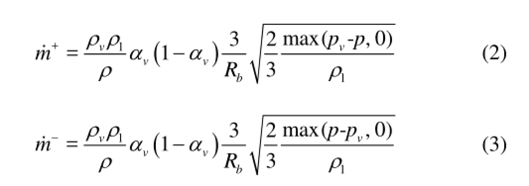
The bubble radius is related to the vapor volume fraction,vα, and the bubble number density,bN, is given as follows

wherebN is the only parameter which needs to be specified and its value is taken as 1013according to the work by Schnerr and Sauer[17]. This cavitation model has been validated for many cases, such as cavitating flow around a 2-D hydrofoil and a 3-D hydrofoil[18].
1.2 Governing equations and the LES approach
In the mixture model for vapor/liquid two-phase flow, the multiphase fluid components are assumed to share the same velocity and pressure. The basic governing equations consist of the mass and momentum conservation equations as follows:
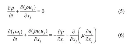
where iu is the velocity component in the i direction and p is the mixture pressure. The laminar viscosity, μ, and the mixture density, ρ, are defined by

Applying a Favre-filtering operation to Eqs.(5) and (6) gives the LES equations


where the over-bars denote filtered quantities. Equation (10) has an extra non-linear term that does not occur in Eq.(6)
which are called the Sub-Grid Scale (SGS) stress and need to be modeled.
One commonly used SGS model is the eddy-viscosity model, which assumes that the SGS stress is proportional to the modulus of the strain rate tensor,, of the filtered large-scale flow,
The SGS turbulent viscosity, μt, and the rate-ofstrain tensor for the resolved scale,Sij, are modeled in the LES WALE model:
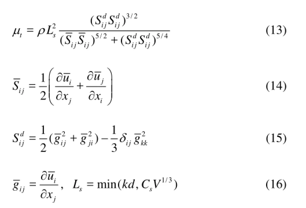
wheresL is the mixing length for the SGS, k von Karman’s constant, d the distance to the closest wall, V the volume of the computational cell andsC the WALE constant having the value of 0.5 based on calibrations using freely decaying isotropic homogeneous turbulence.
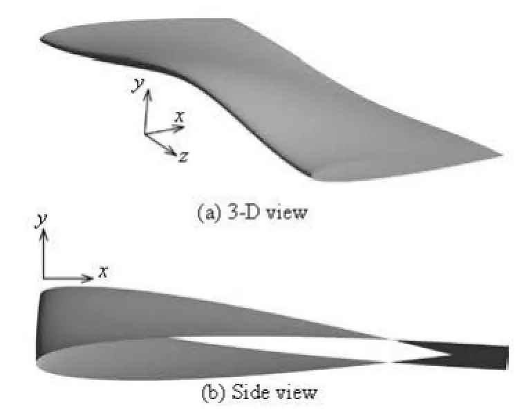
Fig.1 3-D twisted hydrofoil
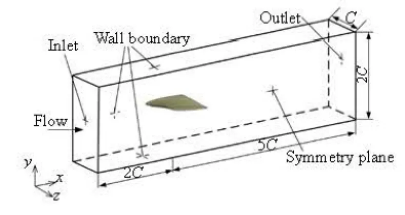
Fig.2 Computational domain and boundary condition
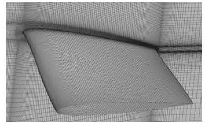
Fig.3 Mesh generation around the twisted hydrofoil surface (=α–2o)
1.3 Simulation procedure
The time-dependent governing equations are discretized in both the space and time domains. The pressure-velocity direct coupling method was used to solve the equations. The second-order upwind scheme was used for the convective term, with the central difference scheme for the diffusion term in the governing equations. The pressure staggering option (PRESTO) was selected for the pressure interpolation with the Quick scheme used for the vapor volume fraction transport equation. The unsteady second-order implicit formulation was used for the transient term. The unsteady cavitating flow simulations were started from a steady non-cavitating flow result. Then, the cavitation model and unsteady solver were turned on for the cavitating flow simulation. The time step was set to 1.076×10⁻⁴s (ref./200T, whereref.=/ TCV∞andV∞is the inflow velocity at the domain inlet) according to the work by Coutier-Delgosha et al.[2]. The simulations were conducted using the CFD code ANSYS-Fluent and the computational time was remarkably reduced by using parallel computational platform of ANSYS-Fluent.
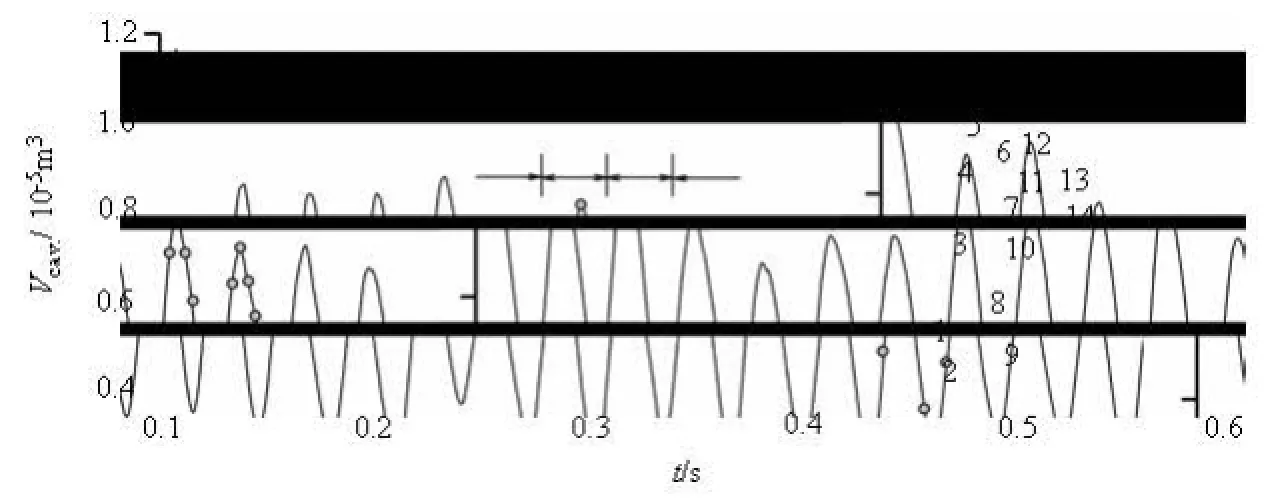
Fig.4 Time dependent total vapor volume,cav.V
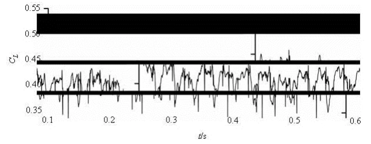
Fig.5 Time dependent lift coefficient,LC
The Delft Twist-11 hydrofoil shown in Fig.1 was used in the present research. The hydrofoil consisted of a NACA0009 profile that had a spanwise varying attack angle from 0oat the tunnel walls to 11oat the mid-section, with symmetry with respect to its midspan plane. The chord length of the foil was =C 0.15 m and the span length was 0.3 m. The attack angle of the entire hydrofoil was –2odegree. The inflow velocity was V∞=6.97m/s . The static pressure was assigned according to the cavitation number (σ= 1.07), which was defined as

The computational domain is shown in Fig.2. The numerical flow simulations used only half of the hydrofoil and the surrounding flow channel because of the geometric symmetry. The hydrofoil was located in a channel with a height 2c, a length of 2c upstream of the leading edge, a length of 5c downstream of the leading edge and a width of c. The boundary conditions had an imposed velocity at the inlet and a fixed static pressure at the outlet, with a symmetry boundary on the midplane, free slip wall conditions at the channel walls and non-slip walls on the hydrofoil. An OH type grid was generated for the domain with sufficient refinement near the foil surface as shown in Fig.3. It is noted that the value of+y calculated at the first grid point away from the hydrofoil surface was around 1 for the entire mesh. The final grid had about 3×10⁶cells.
2. Results and discussion
The twisted design and the larger attack angle in the middle area cause the cavitation to mainly develop near the mid-span area close to the leading edge with a curved closure line. The transient evolution of the cavitating flow can be illustrated through the time history of the total volume,cav.V, wherecav.V is defined as where N is the total number of control volumes in the computational domain, ,viα the vapor volume fraction in each control volume andiV the volume of each cell.

The periodicity of the total vapor volume is shown in Fig.4. The predicted shedding frequency, fcal., can be obtained by a Fast Fourier Transform (FFT) analysis of the total vapor volume. Here, fcal.is31.76 Hz, which is very close to the experimental value (exp.=f32.2 Hz[11]). Once cavity shedding occurs, the lift force on the hydrofoil must vary dramatically. The lift coefficient shown in Fig.5 also exhibits periodic behavior with a time averaged lift coefficient of 0.456, which is closer to the experimental value[11]than other results in the literature[16,18].
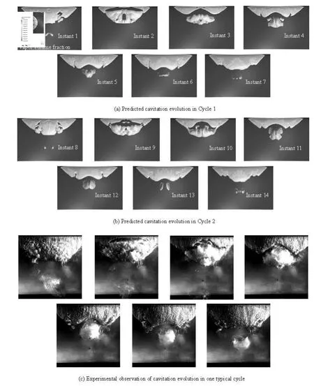
Fig.6 Comparison of observed and predicted cavity volume evolution (σ=1.07)
The unsteady cavitation structures around the Delft twisted hydrofoil are illustrated in Fig.6 with comparison to the experimental observations at times 1-14 within two cycles labeled in Fig.4. For each time, the picture in Fig.6(c) shows a high-speed photography of the experiments by Foeth[11], while that in Figs.6(a) and 6(b) is the numerical result in two cycles as shown in Fig.4. The iso-surface of the vapor volume fraction for αv=0.1 is used to illustrate the cavity shape in the simulation. By comparison with the results of 3-D cavitation structures in Figs.6(a) and 6(b), it can be noted that the predicted cavitating shedding around twisted hydrofoil has remarkably periodicity. In order to show the relationship between the flow structure evolution and cavitation developmentconveniently, seven typical instants at times 1-7 in Cycle 1 is further discussed hereinafter.
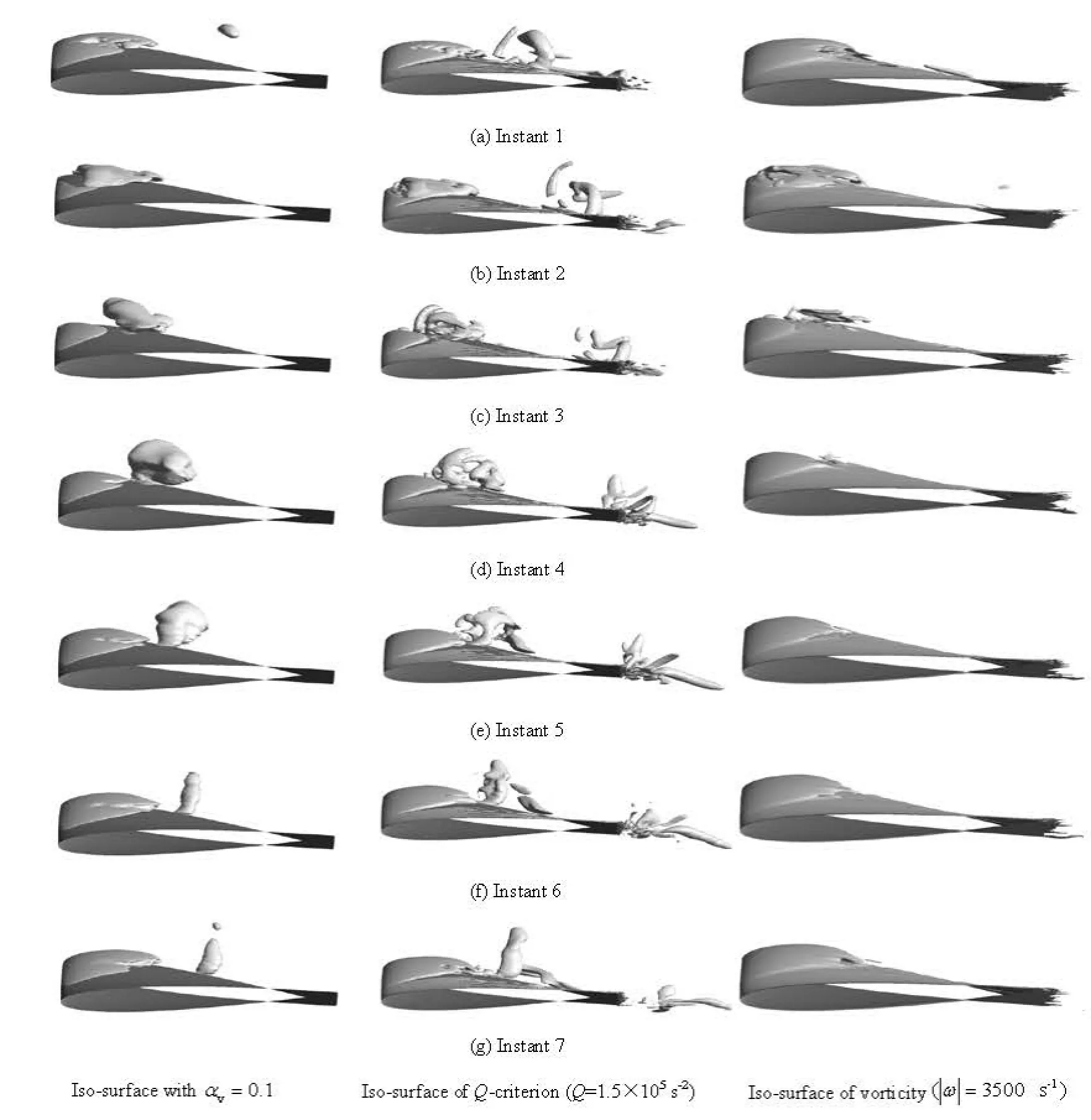
Fig.7 Comparison of 3-D cavitation development and vorticity evolution (σ=1.07)
The cavity shape at Instant 1 in Fig.6 shows that the attached cavity has reached its maximum length and its tail has become convex. The strong adverse pressure gradient in the stagnation region at the downstream end of the cavity forces the re-entrant flow into the vapor structure with a re-entrant jet and a pair of side-entrant jets[11]. And it is noticeable that the cavity interface has changed from a smooth pocket of vapor to a highly turbulent vapor cloud as the re-entrant flow moves from the trailing edge towards the leading edge of the attached cavity. Then, the total cavity volume decreases to a minimum at the Instant 2 (indicated in Fig.4) as the re-entrant flow reaches the leading edge of the attached cavity, which causes the cavity primarily shedding at the center of the hydrofoil in Fig.6. It should be noted that, during this process, the last shed vapor cloud collapses at the downstream.
At the Instant 3 in Fig.6, a new attached cavity grows from the leading edge of the twisted hydrofoil with a concave tail. From Instant 4 to Instant 7 in Fig.6, the shed vapor cloud is advected downstream by the main flow and begins to shrink and finally collapses as it moves downstream. During the cavitation development, the total cavity volume quickly increases to the maximum at the Instant 5, and then decreases dramatically as indicated in Fig.4 due to the shed vapor cloud shrinking and collapsing. Besides, it is noted that the shed vapor cloud has a very clear U-shaped vortex in the final stage of the collapse, especially at Instants 6 and 7.
From the above analysis, it is indicated that the LES simulation adopted in the present work can rea-sonably reproduce the experimentally observed cavity shedding process, including the cavity growth, breakoff and collapse downstream.
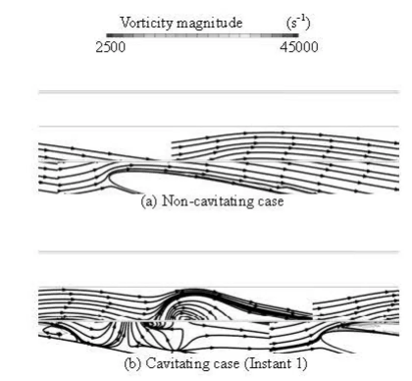
Fig.8 Vorticity magnitude contours and streamline at the midplane of the twisted hydrofoil
According to the review by Arndt[19], cavitation is not only induced by vortical structures but is also a mechanism for vorticity generation. Figure 7 shows the 3-D cavitation and vortex structure around the twisted hydrofoil with three kinds of iso-surfaces. As is shown on the left in Fig.7, the predicted cavity shape is obtained from the vapor volume fraction of 10%. In the middle of Fig.7, the flow structures are visualized based on the Q-criterion (=Q1.5×105s–2), =1/Q 2(Ω2-S2) (where Ω is the vorticity rate, S is the strain rate), to identify the vortices. The iso-surface of vorticity magnitude
is also shown in the right part of Fig.7. By comparison with Figs.6 and 7, we can clearly observe the cavity shedding process and the formation, convection and collapse of a cavitating vortex and the predicted 3-D vortex structures are more complicated by the Q-criterion than those with the iso-surfaces of vapor volume fraction or vorticity magnitude. The transport of the shedding cavitating vortex structure towards the trailing edge is governed by the main flow and the center of the shedding structure is raised above the hydrofoil due to the largest attack angle in the midplane. In order to know this flow mechanism further, the effect of cavitation on the vorticity evolution is illustrated by the instantaneous contours of the vapor volume fraction and vorticity magnitude in the midplane of the twisted hydrofoil.
Although a detailed analysis of the non-cavitating vorticity distributions is beyond the present scope, it is still useful to check the vorticity and streamline distributions for the non-cavitating case in order to verify the correlation between the cavitation and vortical structures. It is shown that the streamline smoothly passes along the upper wall of the hydrofoil in Fig.8(a), which indicates that there is no boundary layer separation and the boundary layer of the non-cavitating flow is thin and attached to the foil except at the trailing edge. When the cavitation number is gradually decreased, the sheet cavitation first appears near the leading edge where the pressure is lowest. As the cavitation number is further reduced to the present case of =σ1.07, the attached sheet cavitation becomes highly unsteady and periodically grows and breaks off to form the cloud cavity. The expansion caused by the cavitation induces boundary layer separation and large increases in the vorticity at the cavity interface, as indicated in Fig.8(b). Figure 9 shows the calculated vapor volume fraction and vorticity fields at several instants within one cycle in the midplane of the twisted hydrofoil. Those results indicate that there is a strong correlation between the cavitation development and the vorticity evolution, which indicates that the cavity shedding and its evolution may correspond to vorticity variation.
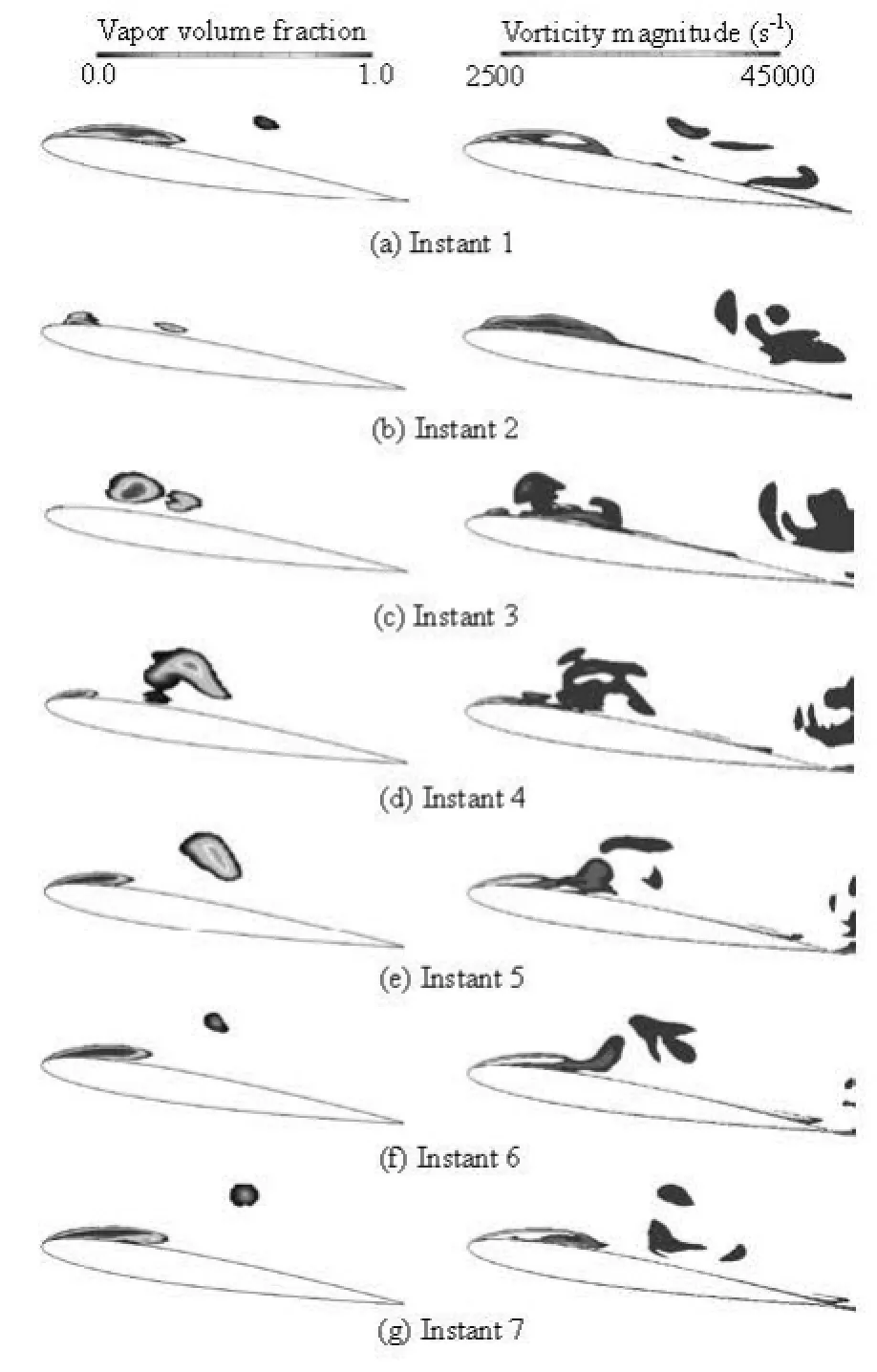
Fig.9 Cavitation development and vorticity evolution at the midplane of the twisted hydrofoil (σ=1.07)
To better understand vortex-cavitation interactions, the vorticity transport equation in a 3-D, variable density flow was employed as shown below

In this equation, the vorticity of a fluid particle includes vortex stretching, volumetric expansion/contraction (dilatation), baroclinic torque (due to misaligned pressure and density gradients), and viscous diffusion. Note that the viscous diffusion term has a much smaller effect on the vorticity transport than the other terms in Eq.(19). Further, for the case without cavitation, the vorticity is mainly transported by vortex-stretching, whose magnitudes are shown in Fig.10.
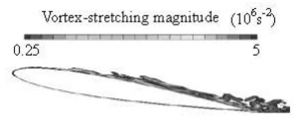
Fig.10 Vortex-stretching term for non-cavitation flow
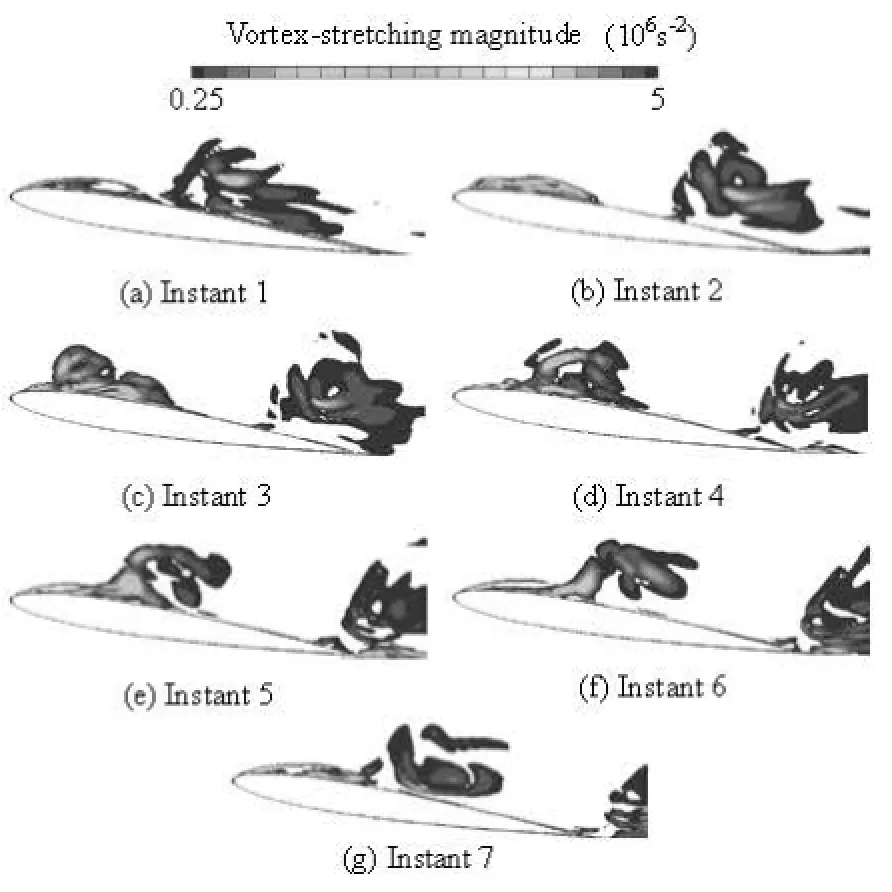
Fig.11 Time evolution of vortex-stretching term within one cycle for =1.07σ
Figure 11 shows several instantaneous contours of the magnitude of the vortex-stretching term, ()⋅∇ωV at =σ1.07 on the midplane of the twisted hydrofoil. This figure shows that the vortex-stretching term is highly dependent on the cavitation evolution. For the cavitation case, the boundary layer is thicker than that for the non-cavitation case, with vortex stretching both along the hydrofoil surface and in the cavitation region. Thus, cavitation promotes the vortex stretching and the flow unsteadiness.
The dilatation term, )(∇⋅ωV, represents the volumetric expansion or contraction of a fluid element due to local density changes and is zero for the noncavitating flow. Vapor formation due to cavitation will result in dilatation of the vorticity transport at σ=1.07 as shown in Fig.12.

Fig.12 Time evolution of the vortex-dilatation term within one cycle for =1.07σ
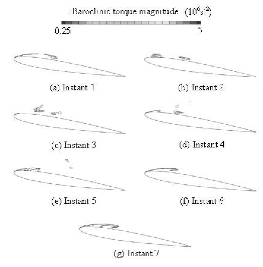
Fig.13 Time evolution of the baroclinic torque term within one cycle for =1.07σ
The baroclinic torque term, (∇ρm×∇p )/ρm2, represents the generation of vorticity due to flow density gradients along constant pressure surfaces. Figure 13 shows the distribution of the baroclinic torque duringone typical cavitation shedding cycle, which reveals that the density gradients within the cavity are not necessarily aligned with the pressure gradients. This phenomenon has been proved by experimental investigation[20].
It is noted that the two terms for the vortex dilatation and baroclinic torque for the cavitating case increase to the same magnitude of the vortex stretching term, while those for the non-cavitating case are identically zero.
3. Conclusions
In this work, the LES method has been used with the WALE SGS stress model and a mass transfer cavitation model to predict unsteady 3-D turbulent cavitating flows around a twisted hydrofoil. The mechanism for the interaction between the cavitation and the vortical flow is illustrated by analyzing the magnitudes of vorticity as well as the vortex stretching, volumetric expansion/contraction (dilatation) and baroclinic torque terms along the midplane. Based on the present simulations and the vorticity analysis, several conclusions can be drawn as follows:
(1) The predicted 3-D cavitation evolutions, including the cavity growth, break-off and collapse downstream, and the shedding cycle as well as its frequency agree fairly well with experimental results.
(2) The vortical flow analysis demonstrates that cavitation promotes the vortex production and the flow unsteadiness. For non-cavitating conditions, the streamline smoothly passes along the upper wall of the hydrofoil, so there is no boundary layer separation and the boundary layer is thin and attached to the foil except at the trailing edge. With the decrease of cavitation number, e.g., the present case of =σ1.07, the attached sheet cavitation becomes highly unstable and periodically grows and breaks off to form a cloud cavity. The expansion due to cavitation induces the boundary layer separation and significantly increases the vorticity along the cavity interface.
(3) Cavitation induces vortex stretching, dilatetion and baroclinic torque which increase the vorticity transport and is the major source of vorticity generation for cavitating flows. Examination of the flow fields reveals that the vortex dilatation and baroclinic torque terms for the cavitating flow increase to the same magnitude as the vortex stretching term, while that for the non-cavitating case is identically zero.
Acknowledgement
The authors would like to appreciate Dr. Foeth E. J. and Prof. Van Terwisga T., Delft University of Technology, for their providing us the experimental data and many helpful discussions.
[1] ARNDT Roger E. A. Some remarks on hydrofoil cavitation[J]. Journal of Hydrodynamics, 2012, 24(3): 305-314.
[2] COUTIER-DELGOSHA O., REBOUD J. L. and DELANNOY Y. Numerical simulation of the unsteady behaviour of cavitating flows[J]. International Journal for Numerical Methods in Fluids, 2003, 42(5): 527-548.
[3] CHEN Ying, LU Chuan-jing and WU Lei. Modelling and computation of unsteady turbulent cavitation flows[J]. Journal of Hydrodynamics, 2006, 18(5): 559-566.
[4] HUANG Biao, WANG Guo-yu. Evaluation of a filterbased model for computations of cavitating flows[J]. Chinese Physics Letters, 2011, 28(2): 026401.
[5] ROOHI E., ZAHIRI A. P. and PASSANDIDEH-FARD M. Numerical simulation of cavitation around a two-dimensional hydrofoil using VOF method and LES turbulence model[J]. Applied Mathematical Modelling, 2013, 37(9): 6469-6488.
[6] GONCALVES E., DECAIX J. Wall model and mesh influence study for partial cavities[J]. European Journal of Mechanics B-Fluids, 2012, 31: 12-29.
[7] LABERTEAUX K. R., CECCIO S. L. Partial cavity flows. Part 2. Cavities forming on test objects with spanwise variation[J]. Journal of Fluid Mechanics, 2001, 431: 43-63.
[8] DULAR M., BACHERT R. and SCHAAD C. et al. Investigation of a re-entrant jet reflection at an inclined cavity closure line[J]. European Journal of Mechanics B-Fluids, 2007, 26(5): 688-705.
[9] FOETH E. J., Van DOORNE C. W. H. and Van TERWISGA T. et al. Time resolved PIV and flow visualization of 3D sheet cavitation[J]. Experiments in Fluids, 2006, 40(4): 503-513.
[10] FOETH E. J., Van TERWISGA T. and Van DOORNE C. On the collapse structure of an attached cavity on a three-dimensional hydrofoil[J]. Journal of Fluids Engineering, 2008, 130(7): 071303.
[11] FOETH E. J. The structure of three-dimensional sheet cavitation[D]. Doctoral Thesis, Wageningen, The Netherlands: Delft University of Technology, 2008.
[12] JI B., LUO X. and WU Y. et al. Numerical analysis of unsteady cavitating turbulent flow and shedding horseshoe vortex structure around a twisted hydrofoil[J]. International Journal of Multiphase Flow, 2013, 51: 33-43.
[13] WANG G., OSTOJA-STARZEWSKI M. Large eddy simulation of a sheet/cloud cavitation on a NACA0015 hydrofoil[J]. Applied Mathematical Modelling, 2007, 31(3): 417-447.
[14] SHANG Z., EMERSON D. R. and GU X. J. Numerical investigations of cavitation around a high speed submarine using openfoam with LES[J]. International Journal of Computational Methods, 2012, 9(3): 1250040.
[15] ZHANG L. X., KHOO B. C. Computations of partial and super cavitating flows using implicit pressure-based algorithm (IPA)[J]. Computers and Fluids, 2013, 73: 1-9.
[16] BENSOW R. E. Simulation of the unsteady cavitation on the the delft Twist11 Foil using RANS, DES and LES[C]. Proceedings of the 2nd International Symposium on Marine Propulsors. Hamburg, Germany, 2011.
[17] SCHNERR G. H., SAUER J. Physical and numerical modeling of unsteady cavitation dynamics[C]. Proceedings of 4th International Conference on Multiphase Flow. New Orleans, USA, 2001.
[18] LI D. Q., GREKULA M. and LINDELL P. Towards numerical prediction of unsteady sheet cavitation onh hydrofoils[J]. Journal of Hydrodynamics, 2010, 22(5Suppl.): 741-746.
[19] ARNDT R. E. A. Cavitation in vortical flows[J]. Annual Review of Fluid Mechanics, 2002, 34: 143-175.
[20] GOPALAN S., KATZ J. Flow structure and modeling issues in the closure region of attached cavitation[J]. Physics of Fluids, 2000, 12(4): 895-911.
10.1016/S1001-6058(11)60390-X
* Project supported by the National Natural Science Foundation of China (Grant Nos. 51206087, 51179091) the Major National Scientific Instrument and Equipment Development Project (Grant No. 2011YQ07004901), and the China Postdoctoral Science Foundation (Grant Nos. 2011M500314, 2012T50090).
Biography: JI Bin (1982-), Male, Ph. D.
LUO Xian-wu, E-mail: luoxw@mail.tsinghua.edu.cn
猜你喜欢
杂志排行
水动力学研究与进展 B辑的其它文章
- Ship bow waves*
- Progress in numerical simulation of cavitating water jets*
- Numerical simulation of shallow-water flooding using a two-dimensional finite volume model*
- Dynamical analysis of high-pressure supercritical carbon dioxide jet in well drilling*
- Micropaticle transport and deposition from electrokinetic microflow in a 90obend*
- Simulation and analysis of ice processes in an artificial open channel*
