EFFECT OF ESCAPE DEVICE FOR SUBMERGED FLOATING TUNNEL (SFT) ON HYDRODYNAMIC LOADS APPLIED TO SFT*
2012-08-22DONGMansheng
DONG Man-sheng
School of Civil Engineering, Hefei University of Technology, Hefei 230009, China
State Key Laboratory of Ocean Engineering, Shanghai Jiao Tong University, Shanghai 200030, China, E-mail: dongmans@sohu.com
MIAO Guo-ping
State Key Laboratory of Ocean Engineering, Shanghai Jiao Tong University, Shanghai 200030, China YONG Long-chang, NIU Zhong-rong, PANG Huan-ping, HOU Chao-qun
School of Transportation Engineering, Hefei University of Technology, Hefei 230009, China
(Received Dcember 4, 2011, Revised February 20, 2012)
EFFECT OF ESCAPE DEVICE FOR SUBMERGED FLOATING TUNNEL (SFT) ON HYDRODYNAMIC LOADS APPLIED TO SFT*
DONG Man-sheng
School of Civil Engineering, Hefei University of Technology, Hefei 230009, China
State Key Laboratory of Ocean Engineering, Shanghai Jiao Tong University, Shanghai 200030, China, E-mail: dongmans@sohu.com
MIAO Guo-ping
State Key Laboratory of Ocean Engineering, Shanghai Jiao Tong University, Shanghai 200030, China YONG Long-chang, NIU Zhong-rong, PANG Huan-ping, HOU Chao-qun
School of Transportation Engineering, Hefei University of Technology, Hefei 230009, China
(Received Dcember 4, 2011, Revised February 20, 2012)
This paper presents a potential approach to settle the problem of surviving major safety accidents in Submerged Floating Tunnel (SFT) that detachable emergency escape devices are set up outside SFT. The Computational Fluid Dynamics (CFD) technology is used to investigate the effect of emergency escape devices on the hydrodynamic load acting on SFT in uniform and oscillatory flows and water waves by numerical test. The governing equations, i.e., the Reynolds-Averaged Navier-Stokes (RANS) equations and kε- standard turbulence equations, are solved by the Finite Volume Method (FVM). Analytic solutions for the Airy wave are applied to set boundary conditions to generate water wave. The VOF method is used to trace the free surface. In uniform flow, hydrodynamic loads, applied to SFT with emergency escape device, reduce obviously. But, in oscillatory flow, it has little influence on hydrodynamic loads acting on SFT. Horizontal and vertical wave loads of SFT magnify to some extend due to emergency escape devices so that the influence of emergency escape devices on hydrodynamic loads of SFT should be taken into consideration when designed.
Submerged Floating Tunnel (SFT), conceptual design, flow, Airy wave, escape device, hydrodynamic load
Introduction
The Submerged Floating Tunnel (SFT), called the Archimedes bridge, is a new concept for crossing waterways. Under united action of the surplus buoyancy and the anchoring system, SFT can float in the proper situation of water. SFT is a thoroughly new structural form of transportation, which can be used as transportation infrastructure for railway or road or railwayroad. Its operating environment is extremely complicated, and its construction involves many science and engineering problems. It is undoubtedly a great challe-nge for the science and engineering community, which attracts a large number of scholars to do early-stage basic research[1-3]. Mai et al.[4], Chen et al.[5]and Ge et al.[6]focused on the vortex-induced vibration of the SFT’s anchoring structure. Pilato et al.[7]were devoted to dynamic response of SFT to spatial seismic and wind wave loads. Walter and Grantz[8]and Jakobsen[9]presented conceptual design of SFT structure under various environments. Mazzolani et al.[10]investigated the system behavior of SFT prototype in the Qiandao Lake in presence of the environmental loads. Of course, some research achievements of coastal and ocean engineering, such as those about submerged horizontal tube[11], could be applied to SFTs directly.
In October, 2010, the first international symposiumon Archimedes bridge (ISAB-2010) was held in the Qiandao Lake of Zhejiang Province, China. The newest international research achievements of SFT were shown at the conference, particularly includingSFT’s dynamic response under environmental loads, new conceptual design, construction technology, cost evaluation, risk estimate and control, and so on[12-15]. The research progress in prototype SFT in the Qiandao Lake constructed by the reseachers from China and Italy together[16-18], was a bright spot, which would motivate further research in the area of STF’s technology and its technology application, and in particular, promote constructing the potential first SFT in the Qiandao Lake. Xiang et al.[15]elucidated the risk index system of public safety of SFT and risk assessment methods, and evaluated the public safety risk during construction and operation of the SFT prototype in the Qiandao Lake. But, up to now, there has been yet no literature focusing on the issue of emergency escape from SFT.
There is no real SFT being constructed or having been constructed up to now, an important factor of which, except for technological and social reasons, is STF’s safety problem. If car explosion, fire disaster, or terrorism activity happened in the tunnel, how we could ensure the passengers safety in the tunnel and decrease casualties as much as possible. The safe escape facilities in the existing SFT’s conceptual design are set inside the tunnel. Safe passages are mainly set near both sides of the tunnel. But, when an accident happens to SFT, the inner safe passage is not very safe. It takes a lot time to escape from emergency situations so that success rate of escape would be reduced very much. Until now, there is no effective method to solve escaping problem when a serious safety event happens to SFT. For SFT’s safety problem, the present paper presents a possible solving method, namely installing separable escape devices outside SFT. Then a conceptual design of the separable escape devices is given. Further to the separable escape devices, based on Fluent Solver of computational fluid mechanics, the flow field outside SFT is simulated which are either set with escape devices or not, to investigate the influence of escape devices on SFT’s hydrodynamic loads in uniform flow, oscillatory flow and linear waves. It provides a new mode of thought and a theory store for escape system research and design of SFT.
1. A new escape scheme for SFT
In all the existing SFT’s conceptual design, it was suggested that the distance from the tunnel crown to the water surface is from 10 m to 30 m. The axial length of SFT is relatively long. When major security incidents happen, especially fire disasters, it is very difficult for passengers to escape safely, that is, the success rate of escape is lower. In view of this situation, separable escape devices for SFT have been designed to be used to escape in emergency situations, which has obtained a patent license authorized by Chinese National Patent Office[19]. Subsequently separable escape device conceptual design is presented. The conceptual structure shape given in the following figures is only an initial idea, and the shape of structure depends on specific environments and escape function requirements when applied.

F ig.1 Vertical view of SFT with escape device

Fig.2 A-A section schematic
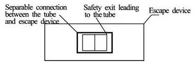
Fig.3B-B view schematic
The conceptual design of escape devices is shown in Figs.1, 2, and 3. In Fig.1, the SFT’s tunnel tube is fixed on the bottom of water by mooring system. Four escape devices are set on both sides of SFT symmetrically and the crown of every escape device is set up with a waterproof safety exit. In practical application, according to SFT’s length and transportation capacity, and also according to real requirements, an appropriate number of escape devices is set up outside the SFT.
In light of Figs.2 and 3 the main scheme of emergency escape is presented as follows. An emergency exit leading to escape devices is set at the outside wall of SFT, and the bottom of the emergency exit is a little higher than the pavement. Corresponding with emergency exit at SFT wall, an escape device is set up, whichis connected with tunnel tube flexibly by linkage. Waterproof safety exit is put up on the near side of the escape device. The tunnel tube leads to escape devices by emergency exit and waterproof safety exit. The opening switches are put up on both sides of waterproof safety exit. By turning on or off the switches installed in the external sides of the waterproof safety exit, the escape device is separated from or connected with the tunnel tube. The escape device could be made from metals or organic materials or concrete, and also made from the mixture of these, but the buoyancy of the escape device in water must be slightly larger than the total gravity of the escape device and a certain number of escaping people.
When an SFT is working normally, the escape devi ce and the tunnel are fastened together. When a safety event happens, passengers can enter the nearest escape device, close the two seal safety doors, and switch on the tipper to achieve separation of the escape device from the tunnel. The escape device is to go up to the water surface under buoyancy force, and then the passengers can escape from the emergency exit on the top of the escape device. The passengers can escape from the scene quickly by the escape device. Compared with the method of setting safe passage on both inner sides of SFT, this approach can save a lot of escaping time, and greatly increases the success rate of escape.
2. Mathematical physics model
2.1 Governing equations
Governing equations of water flow and wave in thisresearch are the two-dimensional incompressible RANS equations
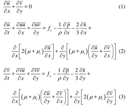
wherefx,fyare the x and y components of volume force respectively, ρis fluid density,μis dynamic viscosity, μtis turbulent viscosity co efficient,vdt are time mean speeds in the x andy directions respectively, andp dt is time mean pressure.
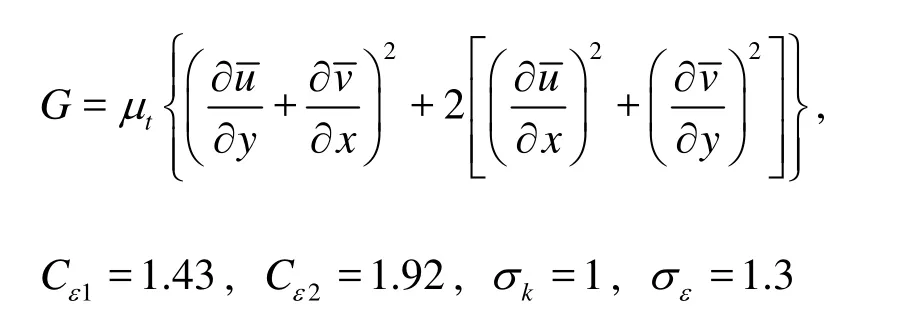
Thek-ε turbulent flow model is used in numerical simulation, which constitutes the closed model together with the RANS equations. Thek-ε turbulent flow mo del is just as follows:

where k is the turbulent kinetic energy,εis the turbulent kinetic energy dissipation rate,and
2.2 Linear wave
The inlet and outlet boundary conditions for the computational region under wave is set bymeans of user-defined boundary function by applying the theoretical solution of linear wave. The two-dimensional water wave theory at a constant water depth is taken into account in this paper, and the coordinate system of which is shown in Fig.4.
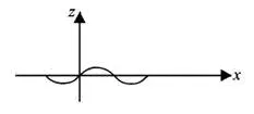
Fig.4 Coordinate system
Fluid velocity of wave motion can be gained from velocity potential φ, namely
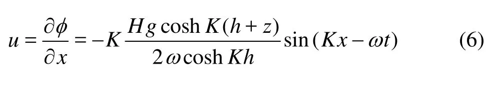
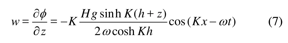
whereφis the velocity potential,gthe acceleration of gravity,H the wave height, K the wave number, andω the circular frequency.
2.3 Physical model
Because SFT’s axial dimension is much larger than transverse dimension and the cross-section along axial direction is invariable, the SFT conceptual design model canbe simplified into a two-dimensional one in order that the characteristics of hydrodynamic load applied to SFT can be easily investigated in theory in the situation that the simplification does not influence the nature of problem analysis.
The cross-section of SFT was designed as 4-lane dual carriageway. Inner width of SFT, including road shoulder, is 15 m and exterior width is 16 m. Because ballast balancing the surplus buoyancy, so packing material and pipeline equipment are taken into consideration, and the clear height of the lanes is not smaller than 4.2 m (the maximum height of the container car is 4.2 m), and the outer height of SFT is set as 7.6 m. The cross-section of escape devices, which are set up on outer sides of the tunnel symmetrically, is 3 m×3 m in dimensions while its axial length is given based on specific quantity of passengers. The sketch of SFT with escape devices is shown in Fig.5. The section of SFT is symmetric about the horizontal and vertical axes respectively.
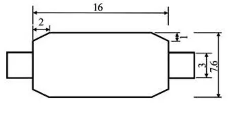
Fig.5 Two-dimensional schematic diagram of submerged floating tunnels with escape devices (m)
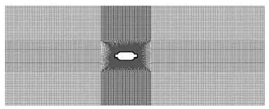
Fig.6Schematic of the grid of SFTs with escape devices
3. Influence of escape devices on hydrodynamic loads acting on SFT under flow
3.1 Computational grid
The computational region scale is 240 m in length and 100 m in height. The distance between the leftor right boundaries and SFT wall surface is over 10 times larger than the section dimension. The geometric model is established by the Gambit pre-processing tool, and the grid is generated in the Gambit. The specific geometric model and grid division are shown in Figs.6 and 7. During dividing the grid, the quality of which is very important for computational convergence, the computational domain is divided into several faces and a transition region, the mesh size of which increases into the same size of the outer fluid field grid from inner to outer gradually, and is erected around the SFT.
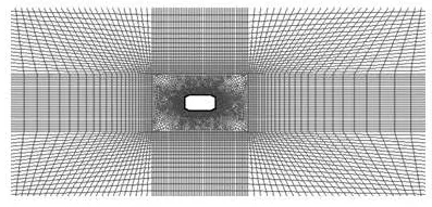
Fig.7 Schematic of the grid of SFTs
3.2 Boundary condition
On the rigid wall of SFT,Γs, the non-slip boundary condition is imposed

Uniform flow boundary conditions are given as follows: the left boundaryof the computational domain is set as the velocity inlet while the right boundary is defined by free flow outlet, namely the normal gradient of physical quantities is 0, and the upper and lower boundary are both symmetrical boundaries.
Oscillatory flow boundary conditions are given as follows: the upper and lower boundary of the oscillatory flow is symmetrical while the velocity of the left inlet is given by a self-defining function and the right boundary is free flow outlet. The amplitudeof the oscillatory flow is 1.4 m/s, and its period is 20 s.
3.3 Numerical algorithm
The Fluent solver is used in the numerical calculation and the finite volume method is applied to solve Eqs.(1)-(5). The Pressure correction method, namely SIMPLE algorithm, is applied to discretize the governing equations. The relaxation factor is set by the defaultvalue. The turbulent kinetic energy and the turbulent dissipation rate are discretized by the first-order upwind scheme. The turbulence intensity is 1% and the hydrodynamic radius is 1 m.
3.4 Results of numerical tests
3.4.1 Influence of escape devices on SFT’s hydrodynamic loads in uniform flow
Here the fluid environment of the researc h objectis two-dimensional steady flowfield, and the momentum equations are discretized by the second-order upwind scheme. Figure 8 shows the ratio of the drag force with escape devices to that not varying with flowvelocity. The uniform flow velocity in calculation is 0.4 m/s, 0.6 m/s, 0.8 m/s, 1.0 m/s, 1.2 m/s and 1.4 m/s respectively.

Fig.8 Schematic of relationship between the ratio ofFdrag_withtoFdrag_withoutand current velocity
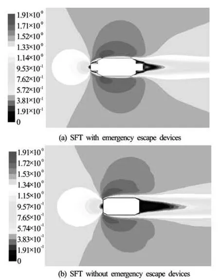
Fig.9 Contours of velocity whenu =1.4m/s
Figure 8 indicates that the ratio ofFdrag_withand Fdrag_withoutis between 0.6 and 0.65. As is shown in Fig.9, the existence of escape devices changes the flow field around the SFT, and the whole shape of flowfield is more approximate to streamline. Thus the differential pressure between the oncoming flow and back flowdecreases. In the view of overall effect, the establishment of escape devices can reduce the drag force applied to SFT.
3.4.2 Influence of escape devices on SFT’s hydrodynamic load in oscillatory flow
The fluid environment is two-dimensional and unsteady. The momentum equations are discretiz ed by the first-order upwind scheme, and the timestep is 0.005 s and the maximum iteration number is 30 per time step. The drag force of SFT subject to flow in a periodis shown in Fig.10. According to Fig.10, it is concluded that the influence of escape devices on the hydrodynamic load applied to SFT is little in oscillatory flow, which is much smaller than that in uniform flow and can be neglected in design. Because the flow field around the SFT in oscillatory flow becomes more complicated and less regular, the existence of escape devices does not change obviously the pressure difference between the left and the right sides of the tunnel.

Fig.10 The drag force applied to SFT during a period
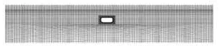
Fig.11 Schematic of the grid of submerged floating tunnels without escaping devices
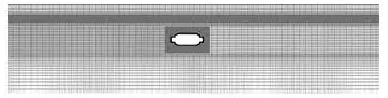
Fig.12 Schematic of the grid of submerged floating tunnels with escaping devices
4. Influence of escape devices on hydrodynamic loads acting on SFT in wave
4.1 Co mputational grids
The scale of computational domain in wave is 400 m×60 m. When the water is static, the water depth in the computational domain is 50 m, the height of the air is 10 m, and the crown of thetunnel is located at 10 m underwater. The distance from the left or right boundary to the nearest SFT’s wall face is over20 ti mes greater than the cross-section scale of SFT. The specific geometric model and grid are shown in Figs.11 and 12. The grid, which is similar with the foregoing in flow, separates the computational domain into several subdomains, and a transition region is established around the SFT where the grid size finally becomes the same as the outer flow field grid from inner to outer gradually. In order to catch the wave surface accurately, the grid near the static water surface is refined.
4.2 Numerical algorithm
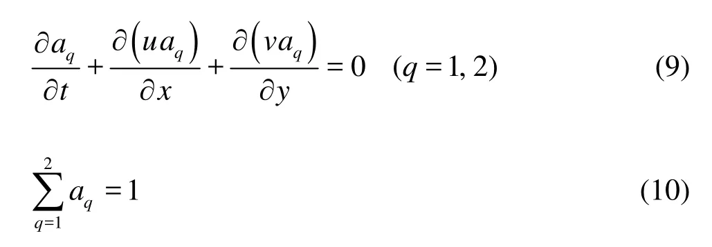
The volume fraction method is applied to track the free surface, in which the volume fraction is introduced, representing the volume of the qth phase fluid per unit volume. aq=0indicates thatthe unit is empty for the qth phase,and aq=1 indicates that it is full of theqth phase. If 0<aq<1, the unit is on the interface. For the problem of waterand air two-phase-flow in wave, aqsatisfies the follow equation:
The finite volume method of numerical algorithm is adopted to solve Eqs.(1), (2), (3), (4) and (5). The PISOalgorithm is used to calculate the flow field. The turbulence kinetic energy and the turbulent dissipation rate are computed with the first-order upwind scheme. The turbulence intensity is 1% and the radius of the hydrodynamic load is 1 m. The relaxation factors adopts the default value in Fluent.
4.3 Boundary conditions and initial conditions
Because the SFT is submerged under the free surface more than 10 m, and the wavelength of simulation is much larger than the cross-section scale (7.6 m). The influence of the existence of SFT on the wave surface is just limited to some region above the SFT and does little to the far field wave surface. Thus theboundary condition is taken to generate water wave in this paper, namely the wave environment is created by defining the flow velocity and the height of the wave surface at inlet and outlet boundaries.
In the boundary-generated wave method, the flow velocity and the height of the wave surface at boundaries are set up by self-defined macro function. Equations (6) and (7) are applied to set boundary flow velocities in the x and z direction and Eq.(10) is applied to set the boundary height of the wave, which is simulated by setting the volume fraction function. The volume fraction of water is 1and that of air is 0. The flow velocities and wave height at the inflow boundary are set as follows: the fluid volume fraction and velocities at the inlet boundary are defined by applying DEFINE_PROFILE (namely t and i) including Eqs.(6), (7) and (10). Obviously the volume fraction and velocities vary with the time. The outflow boundary condition is similar to the inflow one. According to the relationship between wavelength and simulation domain length, the phase difference of flow velocities and wave surface at outflow and inflow boundary conditions are calculated by linear wave theory. Pressure-outlet boundary conditions are adopted at the upper boundary and wall boundary conditions are adopted at the lower boundary.
It begins to generate wave in hydrostatic state. At the initial moment, the wave surface is static, and the pressure is hydrostatic pressure. The initial velocity over the computational domain is 0 m/s. The turbulence kinetic energy k and its dissipation rate ε are set by the value in small disturbance state.
On the rigid wall of SFT,sΓ, the non-slip boundary condition is imposed by Eq.(8).
4.4 Results of numerical test
The purpose ofthe numerical test is to investigate the influence of escape devices on thehydrodynamic load applied to SFT. So the parameters in this paper are as follows: the wavelength is 50 m, the wave amplitude is 2 m, the wave period is 5.66 s, and the water depth is 50 m.
The numerical results indicate that the wave state tends to be steady after the computational physical time is 10 times of wave period. A wave period after 100 s of computational physical time is applied. The horizontal and vertical wave forces are obtained by pressure integration on the SFT surface, as shown in Figs.13 and 14.
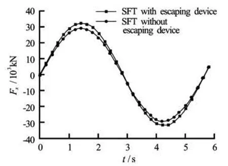
Fig.13 Horizontal wave load of SFT during a period
It is known from Figs.13 and 14 that both horizontaland vertical hydrodynamic loads of SFT withescape devices increase to some extent. The amplitude of horizontal load acting on SFT without escape devices is 2.9×10⁴ N, and that with escape devicesis 3.2× 10⁴ N, which increases by 10.3%. The ampl itude of vertical load of SFT without escape devices is 1.0× 10⁴ N, and that with escape devices is 1.6×10⁴ N, increasing by 60%.

Fig.14Vertical wave load of SFT during a period
5. Conclusions
Concept design of detachable emergency escape devices are presented in detail, which is set up outside SFT. It is a potential approach to settle the problem of surviving major safety accidents in SFT.
The finite volume method is applied to simulate the flow field numerically to investigate the influence of escape devices on hydrodynamic loads acting on SFT in uniform flow, oscillatory flow and linear wave. For rhombic section SFT, escape devices decreases the hydrodynamic load of SFT in uniform horizontal flow sharply, however, the influence of escape devices on the hydrodynamic load of SFT in oscillatory flow is very little and can be neglected in design. In linear wave, both horizontal and vertical wave loads of SFT with escape devices increase to some degree, which is different from that in uniform and oscillatory flow. The influence on vertical wave load is much larger than that of horizon, which should be taken into consideration in real engineering.
In this paper, the problem in the safety system of SFT is focused on giving up the mode of thinking of traditional escape devices inside the tunnel, and the separable escape devices outside SFT are put forward for the first time, which provides a new thought for the study on SFT’s safety. Because the separable escape device in the paper is a preliminary conception which is a potential and feasible scheme and there exists some distance between theory and real engineering, so it is worth expecting to study further the structure optimization of an escape device and its motion rule in water after being distinguished from SFT.
[1] FOGAZZI P., PEROTTI F. Dynamic response of seabed anchored floating tunnels under seismic excitation[J]. Earthquake Engineering and Structural Dynamics, 2000, 29(3): 273-295.
[2] DONG Man-sheng,GE Fei and ZHANG Shuang-yin et al. Dynamic equations for curved submerged floating tunnel[J]. Applied Mathematics and Mechanics (English Edition), 2007, 28(10): 1299-1308.
[3]ZHOU Xiao-jun, GAO Bo. Mechanical behaviors of submerged floating tunnel under current effect[J]. Journal of Southwest Jiaotong University (English Edition), 2007, 15(2): 102-110.
[4]MAI Ji-ting,LUO Zhong-xian and GUAN Bao-shu. The vortex-excited dynamic response for a submerged floating tunnel under the combined wave and current effect[J]. Journal of the China Railway Society, 2005, 27(1): 102-105(in Chinese) .
[5] CHEN Jian-yun, SUN Sheng-nan and WANG Bian-ge. Dynamic analysis for the tether of submerged floating tunnel[J]. Chinese Journal of Computational Mechanics, 2008, 25(4): 488-493(in Chinese).
[6]GE Fei, LONG Xu and WANG Lei et al. Study of vortex-induced vibration of submerged floating tunnel tube-tether coupled model[J].China Journal of Highway and Transport, 2009, 22(3): 83-88(in Chinese).
[7]PILATO M. D., PEROTTI F. and FOGAZZI P. 3D dynamic response of submerged floating tunnels under seismic and hydrodynamic excitation[J].Engineering Structures, 2008, 30(1): 268-281.
[8]WALTER C., GRANTZ P. E. Conceptual study for a deep water, long span, submerged floating tunnel cro- ssing[J]. Procedia Engineering, 2010, 4: 61-70.
[9] JAKOBSEN B. Design of the submerged floating tunnel operating under various conditions[J]. Procedia Engineering, 2010, 4: 71-79.
[10] MAZZOLANI F. M., LANDOLFO R. and FAGGIANO B. Structural analyses of the submerged floating tunnel prototype in Qiandao Lake[J]. Advances in Structural Engineering, 2008, 11(4): 439-454.
[11] XIE Fang-fang, DENG Jian and ZHENG Yao. Multimode of vortex-induced vibration of a flexible circular cylinder[J]. Journal of Hydrodynamics, 2011, 23(4): 483-490.
[12]HONG Y., GE F. Dynamic response and structural integrity of submerged floating tunnel due to hydrodynamic load[J]. Procedia Engineering, 2010, 4: 35-50.
[13] KANIE S. Feasibility studies on various SFT in Japan and their technological evaluation[J]. Procedia Engineering, 2010, 4: 13-20.
[14] CHEN W., HUANG G. Seismic wave passage effect on dynamic response of submerged floating tunnels[J]. Procedia Engineering, 2010, 4: 217-224.
[15] XIANG Y., LIU C. and CHAO C. et al. Risk analysis and assessment of public safety of submerged floating tunnel[J]. Procedia Engineering, 2010, 4: 117-125.
[16] GAO F., YAN W. and GE F. Geotechnical investigation and tension-pile solution for foundation of SFT prototype at Qiandao Lake[J]. Procedia Engineering, 2010, 4: 127-134.
[17] MARTINELLIL., BARBE LLA G. an d FERIANI A. ModelingofQiandaoLakesubmergedfloatingtunnel
subject to multi-support seismic input[J]. Procedia Engineering, 2010, 4: 311-318.
10.1016/S1001-6058(11)60284-9
* Project supported by the China Postdoctoral Science Foundation (Grant Nos. 201003274, 20090460636), the Specialized Research Fund for the Doctoral Program of Higher Education (Grant No. 20090111120016).
Biography: DONG Man-sheng (1973-) Male, Ph. D.,
Associate Professor
[18] MAZZOLANI F. M., FAGGIANO B. and MARTIRE G. Design aspects of the AB prototype in the Qiandao Lake[J]. Procedia Engineering, 2010, 4: 21-33.
[19] DONG Man-sheng, GE Fei and HUI Lei et al. A escaping device of Archimedes bridge[P]. China Patent, 200510105226.9, 2008(in Chinese).
杂志排行

水动力学研究与进展 B辑的其它文章
- EXPERIMENTAL STUDY OF CONDENSATION HEAT TRANSFER CHARACTERISTICS OF HORIZONTAL TUBE BUNDLES IN VACUUM STATES*
- THE NATURAL CONVECTION OF AQUIFERS WITH CONSTANT HEAT SOURCES AND ITS INFLUENCE ON TEMPERATURE FIELDS*
- EXPERIMENTAL STUDY OF AIRFLOW INDUCED BY PUMPING TESTS IN UNCONFINED AQUIFER WITH LOW-PERMEABILITY CAP*
- SIMULATION OF HYDRAULIC TRANSIENTS IN HYDROPOWER SYSTEMS USING THE 1-D-3-D COUPLING APPROACH*
- TOTAL PHOSPHORUS RELEASE FROM BOTTOM SEDIMENTS IN FLOWING WATER*
- EFFECTS OF UNDERSCOUR DEPTH AND HORIZONTAL SPACING BETWEEN TWO BED PROTECTION BLOCKS ON STABILITY OF FRONTAL BLOCK*