近红外消偏振反射镜的设计与制备
2012-08-15刘定权罗海瀚段微波李大琪
尹 欣,刘定权,罗海瀚,段微波,李大琪
(中国科学院 上海技术物理研究所,上海 200083)
Introduction
Polarization coding is a strategy simple and easy to realize in photonic communication process.In the traditional optical fiber communications,birefringence effect[1]seriously interferes with the polarization states and limits the application of polarization coding.With the rapid development of free space photonic communication[2],the impact of fiber on the polarization states information is avoided,the advantages of polarization coding are increasingly apparent.According to the scattering and absorption properties of atmospheric particles,with the aim of reducing the attenuation of the optical signal in space during transmission,people usually select the 810nm,850nm,1.06μm and 1.55μm near atmospheric window as free space photonic communication channel[3].The 810nm and 850nm wavelength channels are especially more developed because the signal sources are easier to be achieved.The information carrier of polarization coding is the different polarization states of lights,and therefore demanding higher requirements for the optical thin film devices in the optical system.Based on the traditional spectrum control,the control of phase separation between polarization components and energy polarization effects of optical system must be considered.
At oblique incidence,the polarization effects of optical multilayer film are difficult to be avoided.In usual optical remote sensing applications,sensible polarization effects will engender the distortion of energy information.And the polarization characteristic of optical signals also contains some available information.For these reasons,with the development of remote sensing technology,more and more applications require the polarization control of optical thin films.Since Baumeister[4]designed first polarization control film in 1961,many researches have been carried out in polarization effect of optic thin films and polarization control film devices;Thelen[5]designed depolarization dichroic filter at oblique incidence for the first time in 1980;John S Seeley[6]designed depolarization dichroic filter with symmetric periodic thin-film structure.
In this paper,the polarization states of linear polarization lights to carry information,in order to control the polarization effects,it′s necessary not only to eliminate the energy difference of the s- and p-polarization components,but also control the phase difference of these two components.For this goal,we designed a mirror with metal layer and dielectric multilayers,and optimized the thickness of the dielectric layers to achieve the control of the phase difference of polarization components.
1 Analysis
In the experiment of space photonic communication based on polarization coding,information is carried by four kinds of linear polarization lights with the interval 45°of the polarization directions(relative to the reference surface 0°,45°,90°and 135°).At the oblique incidence to film surface,the linear polarized lights will be changed from good linear polarization states to elliptical polarization states.Consider the circumstance that the lights′incident surface of the mirror and the reference surface coincident,lights with 45°and 135°two polarization directions changed relatively more obvious,and the extinction ratio(ER,numerically equal to the square of the ratio of long axis and short axis of the elliptically polarized light)declined more.With the decline of ER,the bit error rate of communication will rise.In order to suppress this effect to maintain a low error rate,it′s important to control the polarization characteristics of mirror while realized the reflection functions.According to the requirements of the experiment,mirror works in the 45°oblique incidence,makes wavelength 810nm to 850nm band light reflected and the reflectivity reaches 98%or more.The degrees of polarization Pat 810nm and 850nm two wavelengths are less than 1%,and ERshould be more than 10 000∶1.The degree of polarization Pis calculated as Eq.1:

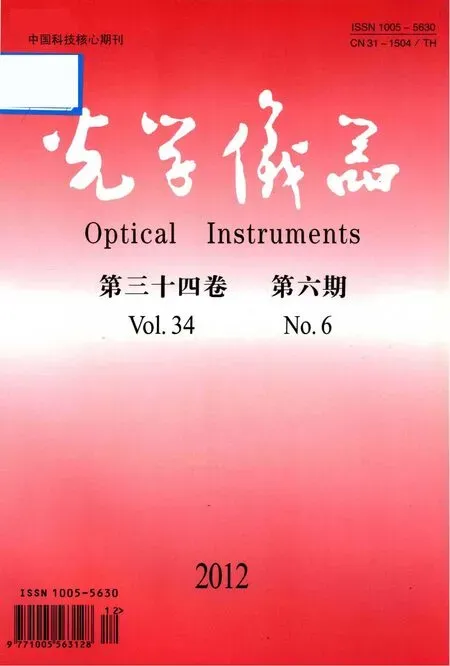
Mirror with Ag film can make the reflectivity of both s-and p-components more than 97%,Pwill be less than 2%But ER will decline because of the phase difference change between the polarization components.The elliptical polarization light caused by ERdecreasing from linear polarization light is shown in Fig.1.According to the electromagnetic field characteristics of light waves,to an elliptical polarization light,exists definite relationship[7]between the phase difference of orthogonal components(δ)and the ratio of the length of long and short axes(a/b),shown as Eq.2:

whereχ=arctan(∓b/a),α=arctan(a2/a1),(a2/a1)is the ratio of amplitudes of orthogonal components s-and p-,as the energies of s- and p-components are very close,it is reasonable of introducing the condition of a1=a2,a result can be get that sin 2α=1.
According to the Eq.2,in the polarization direction of 45°and 135°,the relationship of the phase difference of s-and p-components(δ)and the extinction ratio(ER)of elliptical polarization light can be deduced as Eq.3,ERis always greater than 1∶1.

From Eq.3,we know that ERis a periodic function ofδat 180°cycle,hence the design and optimization of theδtarget value can also be an integer multiple of plus or minus 180°on the basis of the initial target.
The relationship of ERandδof reflection lights from incidence linear polarization lights with polarization direction of 45°and 135°is shown in Fig.2,it shows that ERin the range of higher values is particularly sensitive toδ.
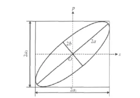
Fig.1 Diagram of electric vector of the elliptic polarized light图1 椭圆偏振光电矢量示意图
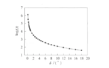
Fig.2 Relationship between the ERand the phase difference of s-and p-components图2 ER与s-和p-分量相位差关系
2 Design
Because of the poor adhesion of the Ag film material,before the Ag layer coating,we have to deposit a layer of other material on the substrate as a matching layer under Ag layer.And Ag film is easy to be oxidized in the air,Ag mirrors for long-term use also need a protective layer of other material above Ag layer.Traditional Ag mirror is with a structure of substrate/matching layer/Ag layer/dielectric protective layer,the dielectric protective layer was usually chosen the material of Al2O3.The major optical properties of a single 100nm Ag layer and a typical Ag mirror with 100nm Ag layer and 30nm Al2O3protective layer are shown in Tab.1.

Tab.1 The major optical properties of Ag layers表1 Ag膜主要光学特性
where Ris the average reflection,Rsis the s-component reflection and Rpis the p-component reflection.
It can be seen from Tab.1,the traditional Ag mirror can meet the basic design requirements in the polarization energy characteristics of the spectrum,but caused a sensibleδ,which led to the ERreduced to about 20∶1,and cannot meet the requirements of the design goals.Therefore continue to deposit layers above the Al2O3layer in order to achieve the control ofδ.The structure is Ag/Al2O3/LHLHL,L and H respectively mean one quarter wavelength optical thickness layer of low and high refractive index material,SiO2and TiO2.Use film design software Film Wizard to optimize the film structure,set the thicknesses of each layers in LHLHL variable,putδas the optimization target,and get the optimized result.
To analyse the tolerance of thickness error of optimized structure,±2%of the monolayer thickness errors of LHLHL was introduced.The major optical properties of the whole mirror structure without and with errors are shown in Tab.2.

Tab.2 The major optical properties of Ag mirrors表2 Ag反射镜主要光学特性
It can be seen from Tab.2,the optimized multilayer structure can meet the requirments.The introducted suitable film thickness errors did not bring on serious decline,is still within the range of the requirements of the design goals,such a film structure is to meet our needs.
3 Fabrication
The all layers were deposited in high vacuum by physical vapor deposition(PVD)method,useing Leybold 900plus optical film coater with ion beam assistant and quartz crystal oscillator.The deposition process was under tempreture 50 ℃ and 5×10⁻³Pa gas pressure.Quartz crystal oscillator layer thickness monitoring was used in all mirror deposition process.Ion beam assist device was used to improve the packing density of TiO2and SiO2material layers[8].
Spectrophotometer was used to measure the spectrum,the reflection curve is shown in Fig.3.In 810nm and 850nm,the reflections are all more than 98%and the degrees of polarization are below 1%.
The ERof depolarization Ag mirror samples was measured by laser measurement platform and V-Vase spectrumscopic ellipsometer from J.A Woollam Company to get independent results to verify.The laser measurement platform contained 810nm and 850nm laser sources,polarizers from Thorlabs Company and a power meter.The results of measurement is shown in Tab.3,and some samples can meet the requirments.

Fig.3 Reflection curves of s-and p-components of a mirror sample图3 反射镜样品s-和p-分量反射率曲线

Tab.3 The ERmeasurement results of mirror samples表3 反射镜样品ER测量结果
4 Conclusion
According to the demands of photonic communication experiment,an Ag depolarization mirror is designed and fabricated.And sample with ERof greater than 10 000∶1was achieved.The mirror is able to reflect signal lights from 810nm to 850nm with an efficiency of 98%while keeping the polarization preferment of lights.
Reference:
[1]WEI Y D,TANG Z L,LIU X B.Study on sending after verify scheme in quantum channel for quantum key distribution system based on polarization coding[J].Acta Photonica Sinica,2009,38(7):1852-1857.
[2]HUANG Y B,WEI H L,MEI H P.Effects of atmospheric channel on system per-formance of infrared laser communication system[J].Acta Photonica Sinica,2009,38(3):646-650.
[3]LI X F,CHEN Y,HU Y.The analysis of wavelength selection for space-to-ground laser communication[J].Applied Optics,2004,25(1):30-33.
[4]BAUMEISTER P.The transmission and degree of polarization of quarter-wave stacks at non-normal incidence[J].Opt Acta,1961,8:105-119.
[5]THELEN A.A voidance or enhancement of polarization in multilayers[J].J Opt Soc Am A,1980,70:118-121.
[6]SEELEY J S.Simple non-polarization high-pass filter[J].Appl Opt,1985,24:742-744.
[7]BORM M,WOLF E.Principles of Optics[M].Beijing:Publishing House of Electronics Industry,2009:21-25.
[8]FAN B,TANG Q.Properties of TiO2films deposited by IAD process[J].Optical Instruments,2004,26(2):64-70.