Lift Enhancement and Oscillatory Suppression of Vortex-induced Vibration in Shear Flow by Loentz Force
2012-07-25ZHANGHui张辉FANBaochun范宝春LIHongzhi李鸿志
ZHANG Hui(张辉),FAN Bao-chun(范宝春),LI Hong-zhi(李鸿志)
(Science and Technology on Transient Physics Laboratory,Nanjing University of Science and Technology,Nanjing 210094,Jiangsu,China)
Introduction
The fluid-structure interaction occurring in the motion of ordnance gives rise to the complicated vibration of structure,and even causes the structural damage.In addition,a negative lift force generated in shear flow,similar to the stall phenomenon encountered in airfoils at high attack angle,is also undesired generally from the practical point of view.Therefore,the investigation on the control of vortex-induced vibration(VIV)phenomenon in shear flow is necessary due to the practical and theoretical importance.
VIV phenomenon of a circular cylinder in shear flow is one of the most basic and revealing problems.Much experimental work has been done to the flow over elastic structure.Griffin[1]has compiled many experiment results to demonstrate the relationship between the cross-flow vibration amplitude and the mass-damping product.Gharib[2],Khala and Williamson[3]exhibited the examples of significant flow-induced vibrations without lock-in.On the other hand,a classic lock-in was observed in the experiments[4-5].Techet and Triantafyllou[6]showed that the free-vibration tests of a uniform cylinder with low equivalent structural damping yield the amplitude response curve as a function of the nominal reduced velocity which is in agreement with previous results[7].
Numerical work has been also done.With the use of a spectral element spatial discretization,Blackburn and Henderson[8]investigated the vortex-induced vibration problem by solving the two-dimensional Navier-Stokes equations in an accelerating frame of reference attached to the cylinder for the Reynolds number valueRe=250.Zhou,So and Lam[9]studied a two-dimensional flow passed through an elastic circular cylinder using the VIC(vortex-in-cell) discrete vortex method to investigate the responses of the cylinder,the induced forces on the cylinder and the vortex structure in the wake.Anagnostopoulos[10]discussed the relationship between the oscillation frequency of cylinder and the natural shedding frequency.The variations of flow field and hydrodynamic force under the different conditions are also discussed.
The control of the blunt-body wake by means of Lorentz force is considered as one of the most practical methods developed,in which the Lorentz force is generated by the electro-magnetic actuators[11-14].The electro-magnetic wake control of a fixed or VIV cylinder in uniform flow has been performed experimentally and numerically in our research group,in which the closed-loop control and optimal control methods were developed to improve its control efficiency[15-17].However,no work has been done for the Lorentz force control of VIV in shear flow.
In this paper,the Lorentz force control of VIV in shear flow is investigated numerically for lift enhancement and oscillatory suppression.The problems discussed are described by the stream function-vorticity equations in coordinates attached on the moving cylinder,coupled with the cylinder motion equation.The hydrodynamic forces on the cylinder surface are directly derived mathematically from the governing equations.In order to show our understanding of the fluidstructure interaction of VIV in the shear flow,the effects of the instantaneous wake geometries and the corresponding cylinder motion on the pressure forces distributed on the cylinder surface are described in one entire period of vortex shed.Moreover,the mechanism of the vibration cylinder control and the increase in lift by Lorentz force in the shear flow are examined,where the Lorentz force is classified into the field Lorentz force and the wall Lorentz force[18].
1 Governing Equations
1.1 Stream Function-Vorticity Equations
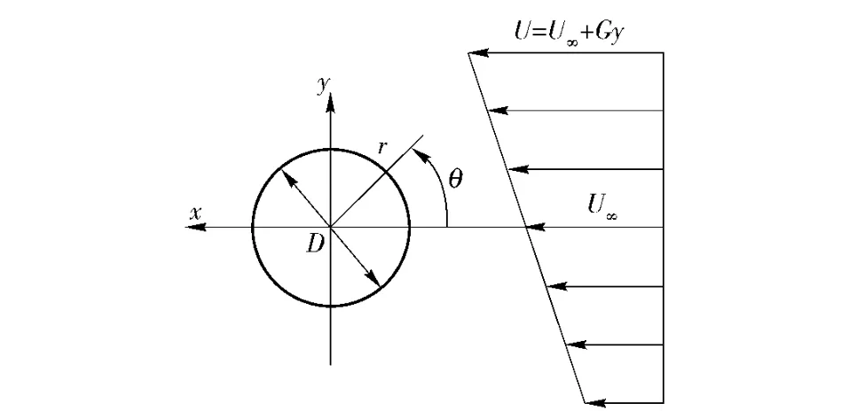
The sketch of shear flow with a linear velocity profileU=U∞+Gyover a cylinder in two-dimensional approach is shown in Fig.1,whereu∞is the freestream velocity at the center-lineθ=0,yis the coordinate in the lateral direction withy=0 at the center of cylinder,andGis the lateral velocity gradient.

Fig.1 Sketch of shear flow over circular cylinder
The shear rateKis defined asK=2Ga/U∞,ais the cylinder radius.Only the case of a positive shear rate(K>0)is discussed in the paper,which implies that the flow velocity on the upper side is faster than that on the lower side.
The coordinates are attached on the moving cylinder,then the stream function-vorticity equations in the exponential-polar coordinates system(ξ,η),r=e2πξ,θ=2πη,for the incompressible electrically conducting fluid becomes


The Lorentz forceFis defined as[11-12]

where the valueαdescribes the electromagnetic penetration into the fluid.
1.2 Initial and Boundary Conditions
The flow is considered to be inviscid initially.If the cylinder is constrained to move only in cross flow direction,the initial flow field in the moving frame of reference can be described by

and

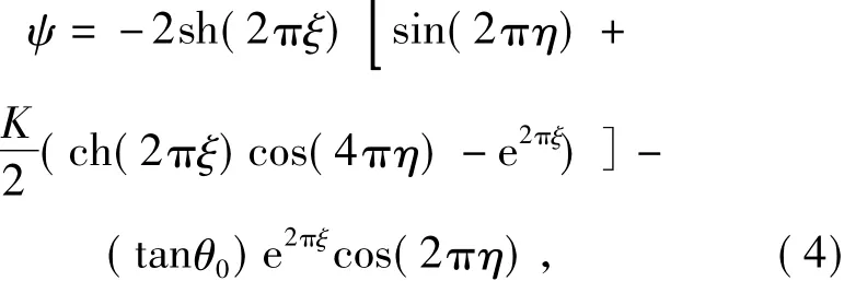
Att> 0,in the far fieldξ→∞,regarded as an inviscid flow,e2πξ→2sh(2πξ),then we have

which are dependent on the shear rateKand the cylinder vibration,and

On the cylinder surfaceξ=0,the no-slip boundary condition is used instead of the slip boundary condition,then

1.3 Cylinder Response
The effective mass including the cylinder mass plus the added mass due to the acceleration of the cylinder in the moving frame of reference should be considered,and thus the cylinder motion is governed by the equation


1.4 Hydrodynamic Force
The Lorentz force is divided into the field Lorentz forceFθ|ξ>0and the wall Lorentz forceFθ|ξ=0.The field Lorentz force affects the flow field in the boundary layer and in turn changes the hydrodynamic force on the cylinder surface.Whereas,the wall Lorentz force does not have any relationships with the flow field in spite of the increase in pressure due to its action on the cylinder surface.Hence pressureconsists ofinduced by the field Lorentz force,induced by the wall Lorentz force andinduced by the inertial force.

where


The calculation has been performed numerically.The equation of vorticity transport is solved by using the alternative-direction implicit(ADI)algorithm,and the equation of stream function is integrated by means of a fast fourier transform(FFT)algorithm.The cylinder motion is calculated by solving Eq.(10)using the Runge-Kutta method.The numerical results in the paper were obtained forRe=150 with the computational step size Δξ=0.004,Δη=0.002 and Δt=0.005.More details about the numerical method,grid consistency and validation of the code can be found in Ref.[15-18].
2 Results and Discussions
2.1 VIV of Circular Cylinder in Shear Flow
A sequence of calculated VIV cylinder wake forK=0.2 in a shedding cycle are exhibited by the shaded vorticity contours in Fig.2,where the upper side refers to the negative vortex,and lower side to positive.The cross-hairs mark the equilibrium cylinder position.Since the vortex is shed at a different positions related to the cylinder,the vortex street formed is composed of two parallel rows with an opposite sign of the vortices.The vortex street inclines toward the lower side and the strength of upper vortex is larger than that of lower vortex due to the background vorticity.
In order to further understand the effect of the flow pattern over the cylinder on the hydrodynamic force,it is essential to know exactly the pressure distribution on the cylinder surface since the pressure is an order of magnitude larger than the shear stress[19-20].The distribution of pressure coefficient on the cylinder surface at different typical timesA-Dare shown in Fig.3,which is composed ofandbased on Eq.(11)whereis generated by the flow field,andis related with the inertial force.The cylinder displacement will strengthen the shear layer on the side where the fluid is pushed by the cylinder and weaken the shear layer on the other side.Hence the pressure on the strengthened side decreases,whereas the pressure on the weakened side increases.Subsequently,the lift directing to the strengthened side is generated,which is in contrast with that due to the effect of the vortex shedding.With the background vorticity,the shift of the stagnation point causes the shift of the positive pressure area to the same side,and the maximum vibrating amplitude of cylinder at timeBis larger than that at the timeD.

Fig.2 A sequence of snapshots of vortex-induced vibration at typical times for K=0.2

Fig.3 Distribution of pressure coefficientalong the surface of the vibrating cylinder at the typical times for K=0.2
The inertial force due to the acceleration of the cylinder also affects the distribution of pressure on the vibrating cylinder,denoted as.Fig.4 shows thedistributions at different stages of one cycle.At the timesAandC,the accelerationis equal to zero,and then increases to reach the values at the timeBandDwhere the value at the timeBis larger than that at the timeD.It is obvious that the lift increases with the increase in the inertial force in the accelerating direction,whereas the drag is independent of the inertial force.

Fig.4 Distribution of pressure coefficientalong the surface of the vibrating cylinder at the typical times for K=0.2
The variation of lift force coefficientClwith timetwithout Lorentz force control att<650 is shown in Fig.5,which vibrates periodically with the effect of vortexes shedding and the mean value is negative due to the background vorticity.

Fig.5 Variation of lift coefficient Cl with time t before and after asymmetric Lorentz force control for K=0.2
2.2 Control of VIV in Shear Flow by Asymmetric Lorentz Force
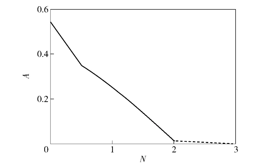
The vibration amplitude has a strong relationship with Lorentz force.The variation of amplitude of controlled VIV with the interaction parameterNforK=0.2 is shown in Fig.6.The limiting amplitude decreases with the increase inN,and the cylinder is fixed finally,ifNis large enough.

Fig.6 Limiting amplitude of oscillating cylinder displacement after control versus the interaction parameter N for K=0.2
With the application of Lorentz force(N=3 on the upper side andN=2 on the lower side)att=650,the vibration of lift is suppressed gradually and the value of lift tends to 0 att>650,as shown in Fig.5.Att=760,the lift is stable and the value is 0 which corresponding flow field is shown in Fig.7.

Fig.7 Snapshot of vortex-induced vibration controlled with asymmetric Lorentz force(N=3 on the upper side and N=2 on the lower side)for K=0.2
The distribution of pressure coefficientgenerated by wall Lorentz force is shown in Fig.8.The curve is positive and the pressure on the lower side is larger than that on the upper side with the application of asymmetric Lorentz force.Therefore,the lift is increased by wall Lorentz force.

Fig.8 Distribution of pressure coefficientwith asymmetric Lorentz force control(N=3 on the upper side and N=2 on the lower side)for K=0.2

Fig.9 Distribution of pressure coefficient with asymmetric Lorentz force control(N=3 on the upper side and N=2 on the lower side)for K=0.2
The displacement time history of the vibrating cylinderwith the shear incoming flow before and after control of asymmetric Lorentz force(N=3 on the upper side andN=2 on the lower side)is shown in Fig.10.The vibration amplitude of the cylinder decreases considerably,and the displacement tends to 0 gradually.Att=760,the displacement is stable.
3 Conclusions
The electro-magnetic control of vortex-induced vibration of a circular cylinder in shear flow has been investigated numerically.To solve the coupled system,the coordinates are attached on the moving cylinder.

Fig.10 Displacement of VIV cylinder before and after control(N=3 on the upper side and N=2 on the lower side)for K=0.2
The initial and boundary conditions and the pressure distribution are deduced on the exponential-polar coordinates system.The conclusions drawn are summarized below.
1)For VIV cylinder in shear flow,the vortex street is composed of two parallel rows with an opposite sign of the vortices which inclines toward the lower side and the strength of upper vortex is larger than that of lower vortex.The lift force vibrates periodically with the effect of vortexes shedding and the mean value is negative due to the background vorticity.
2)The Lorentz force for controlling the VIV cylinder is classified into the field Lorentz force and the wall Lorentz force.The field Lorentz force can be applied to suppress the oscillation of lift,and in turn to suppress VIV.Moreover,the asymmetric wall Lorentz forces can be applied to increase the lift.Therefore,the lift amplification and oscillatory suppression can be obtained by suitable asymmetric Lorentz forces.
[1]Griffin J H.The mechanics of the formation region of vortices behind bluff bodies[J].Journal of Fluid Mechanics,1966,25:401 -413.
[2]Gharib M R.Vortex-induced vibration absence of lock-in and fluid force deduction[D].Pasadena,CA:California Institute of Technology,1999.
[3]Khalak A,Williamson C H K.Fluid forces and dynamics of a hydroelastic structure with very low mass and damping[J].Journal of Fluids Structure,1997,11:973 -982.
[4]Brika D,Laneville A.Vortex-induced vibration of a long flexible circular cylinder[J].Journalof Fluid Mechanics,1993,250:481-508.
[5]Hover F S,Miller S N,Triantafyllou M S.Vortex-induced vibration of marine cables:experiments using force feedback[J].Journal of Fluids Structure,1997,11:307-326.
[6]Techet A H,Triantafyllou M S.The evolution of a‘Hybrid’shedding mode[C]//Proceedings of the 1998 ASME Fluids Engineering Division Summer Meeting,Washington DC:1998,21-23.
[7]Williamson C H K,Roshko A.Vortex formation in the wake of an oscillating cylinder[J].Journal of Fluids Structure,1988,2:355-381.
[8]Blackburn H,Henderson R.Lock-in behavior in simulated vortex-induced vibration[J].Experimental Thermal and Fluid Science,1996,12:184 -189.
[9]Zhou C Y,So R M C,Lam K.Vortex-induced vibrations of an elastic circular cylinder[J].Journal of Fluid Structure,1999,13:165 -189.
[10]Anagnostopoulos P.Numerical study of the flow past a cylinder excited transversely to the incident stream Part 2[J].Journal of Fluid Structure,2000,14:853-882.
[11]Weier T,Gerbeth G,Mutschke G,et al.Experiments on cylinder wake stabilization in an electrolyte solution by means of electromagnetic forces localized on the cylinder surface[J].Experimental Thermal and Fluid Science,1998,16:84-91.
[12]Posdziech O,Grundmann R.Electromagnetic control of seawater flow around circular cylinders[J].Eur J Mech B-Fluids,2001,20(2):255 -274.
[13]Mutschke G,Gerbeth G,Albrecht T,et al.Separation control at hydrofoils using Lorentz forces[J].Eur J Mech B-Fluids,2006,25(2):137-152.
[14]Braun E M,Lu F K,Wilson D R.Experimental research in aerodynamic control with electric and electromagnetic fields[J].Progress in Aerospace Sciences,2009,45(1):30-49.
[15]ZHANG Hui,FAN Bao-chun,CHEN Zhi-hua.Computations of optimal cylinder flow control in weakly conductive fluids[J].Computers and Fluids,2010,39(8):1261 -1266.
[16]ZHANG Hui,FAN Bao-chun,LI Hong-zhi.Suppression of vortex-induced vibration of a circular cylinder by Lorentz force[J].Science China Physics Mechanics and Astronomy,2011,54(12),2248-2259.
[17]ZHANG Hui,FAN Bao-chun,CHEN Zhi-hua.Optimal control of cylinder wake by electromagnetic force based on the adjoint flow field[J].European Journal of Mechanics B/Fluids,2010,29(1),53-60.
[18]ZHANG Hui,FAN Bao-chun,CHEN Zhi-hua,et al.Effect of the Lorentz force on cylinder drag reduction and its optimal location[J].Fluid Dynamics Research,2011,43(1):015506.
[19]Fey U,Konig M,Eckelmann H.A new Strouhal-Reynolds-number relationship for circular cylinder in the range47< Re <2 ×10⁵[J].Phys Fluids,1998,10:1547-1549.
[20]Mittal S,Kumar B.Flow past a rotating cylinder[J].Journal of Fluid Mechanics,2003,476:303-334.
猜你喜欢
杂志排行
Defence Technology的其它文章
- Fault Diagnosis Method Based on Fractal Theory and Its Application in Wind Power Systems
- Numerical Simulation of Particle/Matrix Interface Failure in Composite Propellant
- Torque Ripple Suppression Control Strategy for Brushless Integrated Starter/Generator Wound-Field Synchronous Motor
- Monitoring Method for the Electrical Properties of Piezoelectric Transducer
- Molecular Dynamic Simulation for HMX/NTO Supramolecular Explosive
- Research on Microcrack Extension Mechanism of SiCp/Al in the Machining Process
