Advances in thermal energy storage development at the German Aerospace Center (DLR)
2012-06-01LaingDoerteSteinmannWolfDieterTammeRainerrnerAntjeZunftStefan
LaingDoerte,SteinmannWolf-Dieter,TammeRainer,WörnerAntje,ZunftStefan
(German Aerospace Center (DLR), Institute of Technical Thermodynamics, Pfaffenwaldring 38-40, 70569 Stuttgart, Germany)
1 Introduction
Thermal energy storage (TES) is a key element for renewable energy utilization and the improvement of the energy efficiency of heat processes. National and European political goals on energy efficiency and climate gas reductions will require the availability of cost-efficient storage technologies in many application fields, such as combined heat and power plants,industrial process heat and power generation. To date however, for applications in the medium to high temperature range (100~1000 ℃), only limited choice of storage technology is commercially available,leaving a broad field of development needs.
Current research activities at DLR are focused on the high temperature storage applications which include: ①waste heat recovery and improved thermal management for industrial processes in the range of 100~1000 ℃;②concentrating solarthermal power plants (CSP);③adiabatic compressed air energy storage for grid stabilization;④increase of fl exibility of conventional power plants;⑤thermal management in vehicles.
Thermal energy storage systems are classified in three types, after the underlying physical or chemical phenomena: sensible heat storage, latent heat storage and thermochemical heat storage. Furthermore the storage concepts are divided in direct and indirect storage systems. In direct storage systems the heat transfer fluid is also used as the storage medium. In contrast, indirect storage systems utilize different heat transfer fluid and storage medium. The thermal coupling of heat transfer fluid and storage media may be either of direct contact or indirect contact type.
The selection of a TES technology is very much dependent on the specific target process. It is tied to the heat transfer fluid used, to the pressure range of the heat transfer fluid, the temperature boundary conditions, the heat flux level and the storage capacity.Also, the level of technical maturity clearly varies for the different technology options.
At the DLR’s Institute of Technical Thermodynamics,all above given TES technologies are being developed for the high temperature range from 100~1000 ℃.The research focuses on characterization of storage materials, enhancement of internal heat transfer, design of innovative storage concepts and modelling of storage components and systems. Demonstration of the storage technology takes place from laboratory scale to field testing (5 kW~1 MW). All current developments are described in the following sections.
The remainder of the text is dedicated to a description of storage technologies, outlining their basic setups and features, typical applications and aspects of current development efforts.
2 Sensible heat storage
At DLR different types of sensible heat storage technologies are investigated.
(1)Regenerative type concrete storage aiming mostly at the application in parabolic trough power plants using synthetic oil as heat transfer fluid.
(2)Regenerator storage for applications up to 1000 ℃ using air as heat transfer fl uid, which is in direct contract with a solid storage material.
(3)Regenerator type storage with external heat exchanger, applicable for various heat transfer fluids,using air as an intermediate heat transfer fl uid in direct contact to a solid storage material.
(4)Solid media storage based on moving sandlike particulate materials which can be used both as storage inventory and as heat transfer medium.
(5)Molten salt storage for applications in concentrating solar power plants, conventional power plants and industrial waste heat recovery.
2.1 Concrete storage
The development of high temperature concrete storage is aiming at the application in parabolic trough concentrating solar power (CSP) plants, using synthetic oil as heat transfer fluid. In current parabolic trough power plant projects, the two-tank molten salt storage technology is most commonly applied. However, this technology has the disadvantages of high freezing points and high investment costs. The application of solid sensible heat storage technology using concrete as the storage material is expected to be an attractive option regarding investment and maintenance costs[1]. The development of concrete storage has been performed by DLR in close cooperation with the German building company Ed. Züblin A G.
A concrete storage is a solid sensible heat storage,where a tubular heat exchanger for the heat transfer fluid is embedded in the concrete storage material. The tubular heat exchanger is used for transporting and distributing the heat transfer fluid while sustaining the fluid pressure; the storage concrete stores the thermal energy. By this division of the functions, a durable and safe construction is achieved. Concrete storage is an attractive option for high temperature storage applications regarding investment and maintenance costs. Using concrete as solid storage material is most suitable, as it is easy to handle, the major aggregates are available all over the world and there are no environmentally critical components[2].
The thermo-physical properties of the solid storage material, such as density, specific heat capacity,thermal conductivity, coefficient of thermal expansion(CTE), and cycling stability, as well as availability,costs, and production methods are of great relevance.A high heat capacity reduces the storage volume and a high thermal conductivity increases the dynamics in the system. The CTE of the storage material should be similar to the CTE of the material of the embedded metallic heat exchanger. A high cycling stability is important for a long lifetime of the storage unit.With respect to these techno-economic aspects, high temperature resistant concrete was developed as a suitable solid storage material. Long term stability of concrete has been proven by DLR in oven experiments and through strength measurements up to 500 ℃.Material properties of a typical high temperature resistant concrete are shown in table 1 [3].
For a 50 MW parabolic trough solar thermal power plant of the ANDASOL-type [4], using thermal oil as heat transfer fluid and a desired overall storage capacity of 1100 MW heat, a concrete volume of approx. 50 000 m³ is required. It is not possible and reasonable to build a single solid storage in this size for several reasons. Therefore, the storage will be built up modularly from 252 basic storage modules.The dimensions of a basic module are limited e.g. by the available length of the tubes, transport sizes of components and producibility. Preferable dimensions for a basic storage module are shown in Fig.1[2].

Fig. 1 Basic storage module
These basic storage modules are grouped together in series and in parallel to form a storage unit. This storage unit with 63 basic storage modules of about 400 tons each will be thermally insulated in a single housing. For a full-scale storage, four storage units are connected (Fig.2). A concrete storage of that size requires a ground surface of approx. 300 m×100 m.For an ANDASOL-type parabolic trough power plant in Spain the investment costs of the concrete storage system described above have been estimated to approximately 38 Mio Euros [2].

Fig. 2 Set-up of a 1100 MW heat concrete storage from 252 basic storage modules
The simulation of the annual electricity generation of a 50 MW electricity parabolic trough power plant with a 1100 MW heat concrete heat storage shows that such plants could operate for about annually, delivering ca. 3500 full load hours in southern Europe, about 30%of this electricity is generated by the storage system.This number will further increase, when improved operation strategies are applied [1].
Material parameters and storage performance have been validated in a 20 m³ test module in a test facility in Stuttgart. The test module has a total length of 9 m, the length of storage concrete is 8.37 m and the height / width is 1.70 m×1.30 m. The tube register was prefabricated in the plant, transported on site and lifted onto the previously prepared foundation.After concreting, the module was covered with 40 cm mineral wool for lateral and top thermal insulation.In Fig.3, the finished test module without thermal insulation can be seen [5]. The concrete storage test module was connected to a storage heating/cooling test facility, operated with thermal oil as heat transfer medium. Up to August 2012, the system has been operated for approximately 13,000 hours between 200 and 400 ℃ with roughly 600 thermal cycles. Testing has proven the specific storage capacity of 0.66(kW·h)/(m³·K) for the concrete storage test module, no degradation in performance was observed so far.
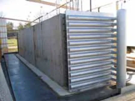
Fig. 3 20 m³ concrete storage test module (without thermal insulation)
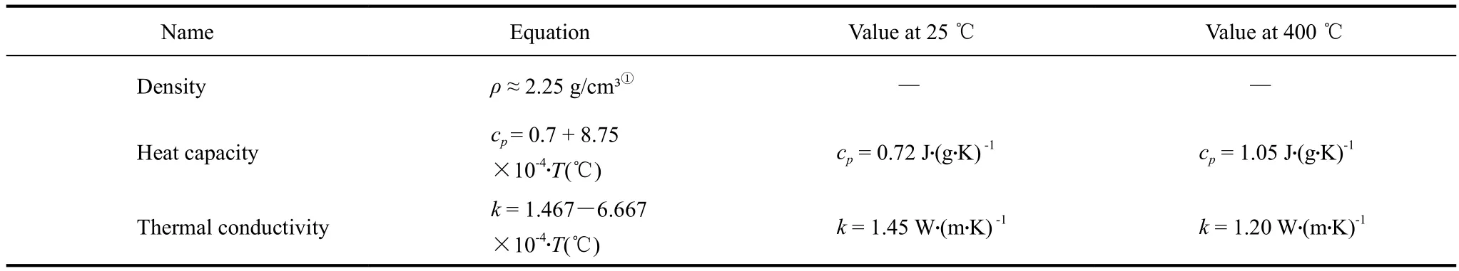
Table 1 Thermo-physical properties of high temperature concrete storage material in a range from 25~400 ℃
2.2 Regenerator storage for air-cooled processes
For applications with gaseous heat transfer media a direct contact between the heat transfer media may allow particularly cost-effective designs. The storage inventory typically consists of a stacked arrangement of regularly shaped refractory brickwork, or, less commonly, of a packed bed, see figure 4 below.Depending on brick geometry, a storage height of up to 50 m is feasible. During the charge period, the hot gas stream passes along the solid storage medium taking up the heat to be stored. Reversing the flow direction allows to discharge the storage and to supply the power cycle at times of insufficient solar radiation.
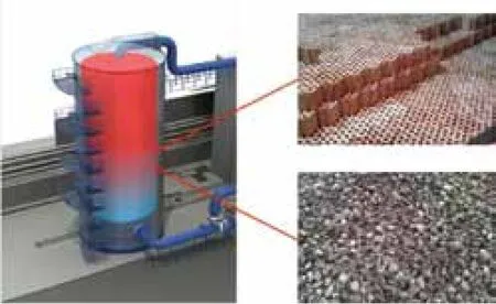
Fig. 4 Heat storage regenerator and inventory materials [6]
Such arrangements, known as regenerator-type heat storages, have a simple setup, they are applicable to highest temperatures and thus have best prospects in target applications using a hot air or a flue gas as a heat transfer medium. Also, the technology is well upscalable to largest modules, offering cost advantages through “economy-of-scale”.
A typical class of storage media is oxide ceramics. This material class offers a broad choice of options with strongly varying qualities, but needs to be narrowed down to ensure compatibility with the heat transfer fluid medium in individual cases, though.
Existing industrial examples include applications in steel industry (hot blast stoves or “Cowper” stoves),glass industry, and for industrial air purification (RTO),where the storage provide either a pre-heating of gas at high temperatures or heat recovery functionality.
Due to its design flexibility, regenerator storage is also well suited for a deployment with further novel applications that move into the focus of interest today.
(1)Adiabatic compressed air energy storage(“Adiabatic CAES”) plants allow the large-scale electricity storage on the basis of compressed air in salt caverns, fostering the grid integration of a fl uctuating power generation from wind and PV. Its high roundtrip eff i ciency of about 70% is due to an improved heat management in the underlying process, which in turn relies on a regenerator storage in gigawatt scale [7-8].
(2)An increased operational flexibility of fossil plants becomes increasingly important in energy systems with a high share of fluctuating renewable energy. Retrofitting combined cycle plants with a regenerator storage in the gas turbine’s flue gas path can be an eff i cient means to this end, this in particular in combination with CHP. In such an application, the storage provides a decoupling of gas turbine and steam cycle operation, allowing for an optimized adaptation to the grid requirement [6].
(3)Solar central receiver power plants based on air-cooled receivers are another well suited application.Both unpressurised and pressurized receiver concepts exist, each resulting in a set of specifications for the regenerator storage. Though first concepts have been looked at in the early 1990s and a regenerator-type heat storage has recently been commissioned in the Jülich solar tower plant [9], the required solar-specif i c adaptation is still an object of on-going research [9-12].
All of these applications are subject of various project activities at DLR, covering all aspects from the development of simulation tools, design studies and material aspects. For the validation of calculation tools and concepts, the test bed “HOTREG” has been erected at DLR Stuttgart. Its central element is a five-metre high storage container containing a replaceable internal container, allowing to quickly exchange various storage setups, see Fig. 5 below. All determining operating parameters such as the temperature, pressure,air flow and air humidity can be varied across a wide range.

Fig. 5 Test rig HOTREG at DLR Stuttgart
Among the technical risks of the technology, a possible maldistribution of the air flow through the inventory may occur with low pressure loss designs,provoking a poor thermal utilization of the material and, finally, an underperforming operation. Therefore,this aspect needs to be properly addressed in the design. One of the origins can be a poorly adapted flow distributor. At DLR, CFD (computational fluid dynamics) models for various shapes of distributors have been set up and used to elaborate optimized designs. Also, correlations for the flow uniformity have been elaborated from CFD parameter studies,providing a simple means to calculate the degree of flow uniformity for an initial design [12].
To leverage further potential of improvement, a packed bed based inventory is a promising alternative to a brick-based arrangement. It offers a large specific heat transfer area and thus a high heat transfer rate, allowing for a compact design. Also, it offers additional freedom for a choice of low-cost materials.Though in use in some applications, such as exhaust air purification with regenerative thermal oxidizers(RTO), packed bed storage has no industrial large-scale examples today. However, the further increased range of usable materials and the substantial cost reduction potential are giving a clear incentive for further development.
Open questions on packed bed storage include mechanical aspects and their implications for the durability of inventory and insulating materials: the mechanical loads arising from the cyclic thermal expansion and shrinking and the subsequent compaction of the bulk represent a risk for material failures. More specifically, a major concern is that the thermo-mechanical forces acting on small punctiform contact areas could result in breakage of the insulation or bed particles, eventually provoking a premature plant failure.
To tackle such technical risks, investigations on the subject are being conducted at DLR. This includes the development of simulations tools, forming the basis of simulation tools used in parametric studies on low-stress storage designs. The models describe, as a core capability, the inter-particle behaviour in largescale storage implementations in a sufficient degree of detail: based on the discrete element method (DEM),the model calculates the mechanical state and the movements of each individual particle. A coupling of the underlying equations with a thermal model of the regenerator then allows a realistic description of the thermally induced mechanical loads, see Fig. 6 below and references [13-14]for further details. For model validation, a test rig was developed and erected. Main elements are a thermal storage with an inventory of 1.1 tons and air heaters providing a heat rate of 30 kW for an operation at high temperatures, see Fig. 6 (b).

Fig. 6 Calculated normal stress distribution in the packed bed inventory of a regenerator storage (a), test rig for the mechanics of packed bed storage (b)
2.3 Solid media storage with external heat exchanger (“CellFlux” storage concept)
An analysis of the cost structure of two tank molten salt storage and concrete storage systems provides distributions according to Fig. 7 and Fig. 8.While the costs of two tank systems are dominated by the expense for the salt, the heat exchanger represents the major cost factor of the concrete storage concept. For both concepts the potential for further cost reductions is considered to be limited.The development of the CellFlux concept [15]aims at reducing the capital costs of sensible heat storage systems by introducing a new basic concept.

Fig. 7 Capital cost structure for two-tank molten salt storage concept [16]

Fig. 8 Capital cost structure for concrete storage concept [17]
A key element of the CellFlux-concept is the application of cost-effective storage materials like concrete or natural stone. The energy is transferred from the primary heat transfer fluid used in the absorbers to air at atmospheric pressure by local heat exchangers that are arranged very close to the section of the storage volume where the energy should be stored. This keeps the path length for the air flow as short as possible. The air, as an intermediate heat transfer fluid, distributes the energy within the storage volume at low velocities. Therefore, the storage material is arranged to offer a high volume specific surface area, while the distances for conductive heat transfer within the storage material are kept small. In contrast to existing storage concepts using air as the heat transfer fluid, the storage is built up of modules(‘Cells’), dividing the required air flow into small,closed loop air flows (‘Flux’), which circulate locally within a single storage module. Air does not cross the boundaries of such a storage module. A schematic illustration of the integration of a CellFlux storage unit into a CSP-plant is shown in Fig.9. This figure also shows the closed air cycle, the heat exchanger and the storage volume as the three main subcomponents of a single storage cell.

Fig. 9 Simplif i ed scheme of the CellFlux storage concept integrated into a CSP plant
For each of the three main subcomponents various state of the art solutions are available. The identification of the best combination represents a principal task in the development of the CellFlux concept. In a further step of development innovative options for an improved adaptation of the main components to the specific requirements of the CellFlux concept are investigated. Examples for these innovative options are as follows.
(1)Heterogeneous storage volume The local porosity and / or the material of the storage volume should vary. By this variation, the pressure losses at the inlet should be reduced, the heat transfer along the flow path should become more homogenous increasing the average power density. By introducing baffles in the storage volume, the air flow should be redirected within the storage volume, reducing pressure losses, costs and space requirement compared to the application of external bends.
(2)Heat exchanger A minor fraction of the storage material is arranged in direct contact with tubes transporting the heat transfer fluid. This structure is intended to extend the effective heat transfer area of the tubes to the closed air cycle. The outer surface of this structure shows fins or similar structures to increase the heat transfer surface. By using storage material instead of metal the costs can be reduced signif i cantly.Essential for the success of this approach is the overall heat transfer resistance.
(3)Fans The integration of a heat exchanger into the diffuser section of a fan is considered. The aim of this concept is the reduction of the overall pressure losses by a double use of surfaces. The heat transfer coefficient in the diffuser is high due to the high velocity in this section, so the needed heat transfer area can be reduced.
Within a three years project the feasibility of the CellFlux concept will be demonstrated. Theoretical research is complemented by lab-scale experiments.These results will provide the basis for the layout of a pilot storage cell in the 100 kW / 500 kW·h range.This project will deliver the necessary data for the comparison to other storage concepts.
2.4 Solid media storage based on moving particulate materials
Due to their simplicity and cost-effectiveness,solid media storage based on sand-like particulate materials , such as ceramics or natural stones, are particularly promising option for use in solar central receiver plants or in industrial processes. As an important advantage of fine-grained particulates, such a material can be used both as storage inventory and as heat transfer medium. Shown below is a system layout of a solar particle receiver system making use of this storage technology, see Fig. 10.
However, the discharge process relies on an additional component: To extract the stored heat from the particles, a moving bed heat exchanger (MBHE) is considered a favourable technology option. The MBHE is an indirect heat exchanger for fine grained, freeflowing bulk materials that move downwards gravity driven and pass the heat exchanging surfaces, which can be tubes, plates or panels. It offers the advantage of low parasitic load, low investment costs, little need for maintenance and adjustment control as well as a compact design.

Fig. 10 Scheme of a solar tower power plant including storage system and integrated moving bed heat exchanger (MBHX) (a)and temperature distribution in a section of the MBHE (b)
The determining design criteria and the underlying phenomena as well as the related material aspects are part of on-going research work at DLR. Simulations of the MBHE have been conducted using a numerical multiphase model. To come to viable design solutions,the determining parameters, such as initial particle velocity, mean particle size and tube arrangement have been investigated in parametric studies with respect to the thermal performance of the heat exchanger [18].Based on initial simulation results, a test module of such a heat exchanger has been realized.
A test rig has been erected to validate the simulation results. It implements a closed loop of a particle stream integrating a MBHE with a heat rate of 35 kW and a maximum particle temperature of 600 ℃,see Fig. 11 below. A comparison with experiments conducted with a test rig in relevant scale confirms the calculated results: Particle image velocimetry(PIV) measurements show a good agreement with the simulated velocity profiles. The velocity on the tube’s surface is proportional to the inlet velocity and mainly affected by the tube pitch [19]. Further experiments at elevated temperatures for the validation of the heat exchangers thermal performance are work-in-progress.

Fig. 11 Test rig for a moving bed heat exchanger to be used in a particulate storage (a), acrylic glass model of the heat exchanger for PIV measurements (b)
2.5 Molten salt
For temperatures above 100℃, molten salts are attractive candidates for sensible heat storage. The major advantages of molten salts are low costs, high thermal stabilities and low vapour pressures. The low vapour pressure results in storage designs without pressurized vessels. Also, many salts can be operated in air contact without significant degradation. Molten salts can also be used as storage media and as heat transfer fluid, therefore, indirect as well as direct storage concepts are applicable.
In general there is experience with molten salts from a number of industrial applications related to heat treatment, thermochemical reactions and heat transfer. The binary salt mixture NaNO3-KNO3and the ternary salt system KNO3-NaNO2-NaNO3are used in commercial applications. For solar thermal power plants, large-scale two-tank molten salt storage systems with a capacity of several ten thousand tons are commercially available[4]. Typically, a non-eutectic salt mixture of 60% (mass fraction)sodium nitrate and 40% potassium nitrate is utilized [20]. The eutectic mixture of NaNO3-KNO3has a melting temperature of 222 ℃ and the thermal stability limit is at about 550 ℃.One major difficulty with molten salts is unwanted freezing during operation.
DLR’s research is focused on the synthesis of salt systems with low melting temperature and the determination of thermal stability at high temperatures to allow for a wider temperature application range of molten salt storage. Another focus is the development of new molten salt storage concepts for further cost reduction of the technology.
In-house measurements on parts of the liquidus phase diagram of the quaternary reciprocal mixtureK,Li,Na // NO2,NO3[called K,Li,Na//NO2,NO3(eu)]with a fixed ratio NO3/NO2= 0.56 have proven a melting point of 80 ℃ [21], reported previously in literature [22]. Fig. 12 shows differential scanning calorimeter (DSC) and melting point apparatus (MPA) measurement results of the liquidus temperature of this system. The measurement points are marked by an asterisk symbol. For the temperature color code and the interpolation, a Matlab™ function was used (ternplot). The mixture with the lowest liquidus temperature had the mole composition: Li+33%, K+48% and Na+19% with a mole ratio NO3/NO2= 0.56. An unknown quinary system Ca,K,Li,Na//NO2,NO3has been demonstrated, showing even lower melting point. Results will be reported in the SolarPaces 2012.
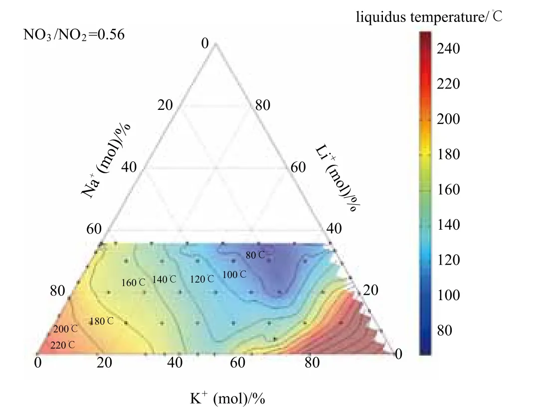
Fig. 12 Parts of the liquidus phase diagram K, Li, Na //NO2, NO3 with fi xed mole ratio NO3/NO2 of about 0.56. The mixture with the lowest liquidus temperature is marked red
In addition, stability measurements by thermogravimetry were conducted for the non-eutectic mixture of 60% (mass fraction) sodium nitrate and 40%potassium nitrate for different partial oxygen pressure and heating rates (Fig. 13) [23]. Results show that the heating rate has a strong impact on the decomposition temperature. Higher heating rates result in higher decomposition temperatures. Also, all measurement series show that a higher partial oxygen pressure leads to a higher decomposition temperature. In other words,the stability of the salt mixture improves with increased partial oxygen pressures. Results were extrapolated to equilibrium conditions (0 K·min-1heat rate), here the decomposition temperatures are 529 ℃ for synthetic air and 562 ℃ for oxygen. The thermal stability limit of 529 ℃ in synthetic air at atmospheric pressure in an open system is lower compared to the previously reported value of 565 ℃ [24]. Measurements refer to a mass loss of 3%. It should be considered that different mass loss definitions will result in other stability limits. Our results confirm a stabilizing effect by increased oxygen partial pressure in open-system type experiments with nitrogen-oxygen atmospheres.

Fig.13 Experimental thermogravimetry results of the thermal stability of 40%KNO3-60%NaNO3 depending on the partial oxygen pressure and the heating rate (0.5 K·min-1 to 5 K·min-1)
To be able to analyze and validate innovative molten salt storage and heat transfer fluid concepts under operational conditions, a molten salt test loop is in the planning stage at DLR, start-up is scheduled for the end of 2013. Testing of new molten salt storage concepts and of the necessary components such as pumps and valves will be of major interest. The chemical behavior between the molten salts and the different materials of the tubes, valves, bearings and packings, as well as stability at different atmospheres will be investigated.
3 Latent heat storage
Regarding efficiency, a fundamental demand for thermal energy storage is the minimization of temperature differences between the heat transfer fluid(heat transfer fluid) and storage medium. This requires an isothermal storage medium for processes using two-phase heat transfer fluid like water/steam with a condensation/evaporation process. An obvious solution is a latent heat storage system.In latent heat storage systems, the storage materials are also named phase change materials (PCM), because of the fact that they change their physical phase from solid to liquid and vice versa. During the melting process, the material absorbs heat, known as melting enthalpy, at constant temperature and correspondently, releases the same amount of heat during solidification, when the storage is discharged. Therefore, in latent heat storage large volumetric energy storage capacities are feasible within a very narrow temperature range around the melting temperature, as the heat of melting and solidification is used.
Applications of these storage systems include the areas of solar thermal power generation with direct steam generation [25]and industrial process steam utilization [26].
For a given PCM, the melting temperature is a material constant at a given pressure. The selection of the PCM strongly depends on the saturation temperature resulting from the pressure in the water/steam cycle.The development of latent heat storage at DLR is focuses on high temperature applications in the 120~350℃ temperature range. In this range,nitrate salts and their mixtures are an attractive choice as PCMs concerning cost aspects and melting temperatures. Four salt systems have already been demonstrated in various lab-scale storage modules: a mixture of NaNO3-KNO3-NaNO2with a melting temperature of 142℃; LiNO3- NaNO3with a melting temperature of 194 ℃; NaNO3-KNO3with a melting temperature of 222 ℃ and NaNO3with 305 ℃melting temperature.
The main disadvantage of nitrate salts is the low thermal conductivity, which is usually around 0.5 W/(m·K). This demands for cost-effective design concepts to overcome the limitations resulting from heat transport properties. At DLR, various concepts to enhance the heat transfer have been elaborated [27].The finned-tube design, using radial [28]or longitudinal[29]aluminum fins has been identified as the most costeffective design, allowing for high heat transfer rates.
Feasibility of high temperature latent heat storage operation has been demonstrated in a pilot scale storage using sodium nitrate as PCM (Fig. 14) [28].The pilot storage consist of a register of steel tubes,applying the specially developed finned-tube design with aluminum fins to reach the required high heat transfer rates between fluid and PCM [30-31]. This tube register is embedded in the phase change material which is hold in a pressureless containment of steel plates. Water passes through the parallel steel tubes for condensation or evaporation. The PCM has a melting temperature of 305 ℃. The pilot scale PCM storage module contains almost 14 t of sodium nitrate with a latent heat of about 700 kW·h. In charging mode, steam with a temperature slightly above saturation properties(typically ~107 bar, ~320 ℃,1 bar=105Pa) is led into the module and condenses. A condensate drain assures that the medium leaves the module only in liquid form.To discharge, the PCM module is flooded with liquid water at a temperature just below saturation properties(typically~80 bar, ~285 ℃). The wet steam produced by the module during discharge is dried in a steam separator. The dry steam is discharged, while the liquid water from the steam separator is recirculated by a pump [31].

Fig. 14 Schematic illustration (a) [30]and photo (b) of the PCM pilot storage module in the water/steam test loop at the power plant Litoral of Endesa in Carboneras, Spain
Demonstration of this world’s largest high temperature latent heat storage was performed successfully in a 1 MW steam test loop at Endesa’s power plant Litoral in Carboneras, Spain, in a test campaign in 2010 and 2011 with 2949 h operation hours and 95 charging/discharging cycles. Cycling tests have proven the expected discharge capacity of about 700 kW·h. System operation in constant pressure mode and sliding pressure mode has been conducted. While in the constant pressure mode the peak power of the storage of more than 700 kW could be demonstrated, in the sliding pressure mode a constant power output over almost the whole charge and discharge period could be provided[32]. Finally,apart from operation in forced circulation, operation in natural circulation and in once-through mode could be demonstrated successfully, showing potential for future cost reductions for the complete storage system. Here,either only the recirculation pump or even the complete circulation cycle including the steam drum could be eliminated [29].
4 Thermochemical storage
A thermochemical storage is a reversible system that collects or releases heat by dissociation or combination of two or more reactants, respectively.Gas-solid reactions are especially suited for this purpose as the reaction products can be easily separated and stored loss-free for an indefinite amount of time.Due to chemical bonds being broken and formed,thermochemical storage systems can achieve very high storage densities while at the same time having the potential for heat transformation by adjustment of the pressure in the reactor. Depending on the chosen reaction system a wide temperature range of storage applications can be covered.
The reaction of calcium oxide and steam to form calcium hydroxide has been investigated for several years at DLR [34,36]. Being a low cost material with excellent availability CaO can be used for heat storage in a temperature range 400~600 ℃. Extensive thermal analysis has shown full reversibility of the reaction system. Reaction kinetics is fast, whereas the low thermal conductivity of the powdery material has to be coped with by suitable reactor concepts. Laboratory scale experiments could prove functionality of a directly heated reactor, where steam and an inert heat transfer fluid are passed directly through a fixed reaction bed (Fig. 15). Nevertheless, pressure drop has to be monitored and moving bed concepts are currently investigated having the potential to decouple the power from the capacity of the storage reactor.An indirect reactor concept being realized as a plate heat exchanger with air as the heat transfer fluid has been built in 5kW-scale with a storage capacity of 20 kW·h at DLR’s competence center CeraStorE® (Fig.16). First test results are very promising and allow for discharge temperatures of 530 ℃ with a thermal power output of 4 kW.

Fig. 15 Test bench for directly heated reactors for the calcium oxide system

Fig. 16 Indirectly heated reactor in 5 kW-scale
Application of this innovative technology in concentrated solar power plants (CSP) is investigated in cooperation with various industrial and research partners, applying the CaO/Ca(OH)2reaction system for parabolic trough plants and the redox reaction of manganese oxide for volumetric air receivers and solar towers. Development and demonstration of a 10 kW storage reactor is realized by tackling the challenges from material side simultaneously with reactor development. System integration with the solar power plant is the key element to define the operating parameters of the thermochemical storages and will be used finally as a basis for techno-economic evaluation of such systems.
On the low temperature end DLR is working on a project to make use of low grade industrial waste heat being available in huge amounts at a temperature below 100 ℃. For such application metal salt hydrides are promising candidates for the thermochemical reaction and calcium chloride could be identified as having a high reaction enthalpy and being reversible and cycling resistant. Based on the experimental results of a detailed thermogravimetric analysis of the CaCl2/H2O(g) system, two different operation modes are possible: an operation mode with a high storage density and one that allows for a higher possible discharge temperature. Whereas the latter one is a thermodynamically controlled gas-solid reaction resulting in a storage density of 220 kW·h/ m3, the very high storage density of 370 kW·h/m3can only be reached if the system reacts to a higher hydration state that includes a phase change of the reaction material.
In order to investigate the influence of heat and mass transfer within the reaction bed, an indirectly heated laboratory reactor containing with a charging and discharging power of 1 kW and a storage capacity of 4 kW·h has been built and tested (Fig. 17). Whereas the gas-solid reaction is limited by heat transfer only for the prevailing conditions, a higher temperature difference between reacting material and heat transfer fluid leads to a faster reaction that is additionally limited by mass transfer. However, as soon as the phase change of the material occurs, the supply of water vapour into the bed is blocked and the reaction only proceeds in regions close to the gas inlet. Therefore an updated setup for the reaction bed is realized currently.

Fig. 17 Test bench for calcium chloride
Another promising option for this reaction system is the possibility of heat transformation by the utilization of excess steam. Latter is used as the heat transfer fluid (1 bar, 100 ℃) in an indirectly heated reactor concept with moist air (0,03 bar, RT) as the reaction fluid to remove the steam being released during the endothermic dehydration reaction. For discharging the steam (1 bar, 100 ℃) is used as the gaseous reactant for the exothermic reaction resulting in a reaction temperature of 170 ℃, which can be transferred to a heat transfer fluid. Thus the change in pressure in the reactor between dehydration and hydration makes a heat transformation by about 50 ℃possible.
5 Conclusions
Thermal energy storage is a key element in all configurations where heat supply and heat demand do not match in time. This is increasingly required in industrial processes where further improvement of heat integration and thermal management usually depends on the availability of storage solutions. Thermal energy storage also contributes to making electricity generation from fossil fuels more flexible and from solar thermal power plants more dispatchable and costeffective.
A characteristic of thermal storage systems is that they are diversified with respect to temperature, power level and heat transfer fluids and that each application is characterized by its specific operation parameters.This requires the understanding of a broad portfolio of storage designs, media and methods.
Today, available heat storage technologies suffer from insufficient energy densities, limited efficiency and reliability, and demand investment costs which are still too high. Such shortfalls are obstacles to a more wide-spread use and market penetration in the industrial and power generation sector. To close this gap, material issues, design aspects, and system integration of energy storage concepts are in the focus of the related research and development activities at DLR, which constitutes one of the worldleading research groups on heat storage at elevated temperatures.
Scientific and technological objectives of the current research activities are as below.
(1)To reduce specif i c storage cost.
(2)To increase the energy density of storage materials and to improve relevant thermo-physical properties of storage materials.
(3)To identify advanced heat transfer mechanism for charging and discharging.
(4)To develop cost effective storage designs.
(5)To identify optimised methods for system integration.
As high temperature storage applications call for adapted storage concepts, DLR is working on various storage concepts, having proven outstanding achievements of the last years are:
(1)Modular, scalable and reliable concrete storage design to be used up to 400 ℃;
(2)Regenerator storage for air-cooled processes for adiabatic compressed air energy storage systems;for increased operational flexibility in combined heat and power fossil plants; and for solar central receiver power plants based on air-cooled receivers;
(3)A new storage concept, combining the experience from concrete storage and regenerator storage development, with external heat exchanger applicable for various heat transfer fl uids (“CellFlux”-storage concept) has been proposed and is developed within the E.ON International Research Initiative;
(4)Moving bed heat exchanger for particle storage using sand-like particulate materials;
(5)Molten salt storage. New salt mixtures with low melting points characterized; a molten salt test loop is in the planning stage, allowing for testing of new molten salt storage concepts and of the necessary components such as pumps and valves;
(6)Latent heat storage. Demonstration of the world’s largest high temperature latent heat storage (700 kW·h, 305 ℃) in a 1 MW steam test loop at Endesa’s power plant Litoral in Carboneras, Spain, with 2949 h operation hours and 95 charging/discharging cycles;
(7)Thermochemical storage with reversible solid-gas reactions. Demonstration of different gassolid reactions for thermochemical storage with very high storage densities in the 1~5 kW-scale.
Acknowledgements
Fundamental work in this paper was funded through the basic DLR funding of the Helmholtz Association. Specif i c support for several projects was given by the German Federal Ministry of Economics and Technology and the German Federal Ministry for the Environment, Nature Conservation and Nuclear Safety. The CellFlux project is funded by E.ON AG as part of the International Research Initiative.Responsibility for the content of this publication lies with the authors.
[1]Bahl C,Laing D,Hempel M,Stückle A. Concrete thermal energy storage for solar thermal power plants and industrial process heat.SolarPACES 2009 elec. Proc.,Berlin,Germany.
[2]Laing D,Lehmann D,Fiss M,Bahl C. Test results of concrete thermal energy storage for parabolic trough power plants.Journal of Solar Energy Engineering,2009,131(4):doi:10.1115/1.3197844.
[3]Laing Doerte,Bahl Carsten,Bauer Thomas,et al. High temperature solid media thermal energy storage for solar thermal power plants.Proceedings of the IEEE (99),2011:1-9.
[4]Relloso S,Delgado E. Experience with molten salt thermal storage in a commercial parabolic trough plant. The Solar PACES 2009,Berlin,Germany,2009.
[5]Laing D,Lehmann D,Bahl C. Concrete storage for solar thermal power plants and industrial process heat. 3rd International Renewable Energy Storage Conference (IRES 2008),Berlin,Germany,2008.
[6]Stahl K,Zunft S,et al. Entwicklung eines Hochtemperatur-Wärmespeichers zur Flexibilisierung von GuD-Kraftwerken. To be published in:Beckmann M,Hurtado A. Kraftwerkstechnik. Neuruppin:TKVerlag,2012.
[7]Zunft S,et al. Adiabate Druckluftspeicher für die Elektrizitätsversorgung. in:Beckmann M,Hurtado A. Kraftwerkstechnik - Sichere und nachhaltige Energieversorgung. Bd. 3,Neuruppin:TK-Verlag,2011.
[8]Marquardt R,Zunft S,et al. AA-CAES-Opportunities and challenges of advanced adiabatic compressed—Air energy storage technology as a balancing tool in interconnected grids. Kraftwerkstechnisches Kolloquium 2008,Dresden. 2008.
[9]Zunft S,et al. Jülich Solar power tower -Experimental evaluation of the storage subsystem and performance calculation.Journal of Solar Energy Engineering,2011,133 (3):1019-1023. doi:10.1115/1.4004358.
[10]Krüger M,et al. Thermodynamic and fluidic investigation of direct contact solid heat storage for solar tower power plants. ISES Solar World Congress 2011 (SWC 2011),Kassel,Aug. 2011.
[11]Zunft S,et al. High-temperature heat storage for air-cooled solar central receiver plants:A design study. Solar PACES 2009,Berlin,Deutschland,Sept. 2009.
[12]Zunft S,et al. Flow distribution calculations in regenerator-type heat storage for solar tower plants. The Solar PACES ,Sept. 2011.
[13]Dreißigacker Volker,Müller-Steinhagen,Hans,Zunft Stefan.Thermo-mechanical analysis of packed beds for large-scale storage of high temperature heat.Heat and Mass Transfer,2010,46 (10):1199-1207. doi:10.1007/s00231-010-0684-5.
[14]Dreißigacker V,Zunft S,et al. Packed-bed heat storage:A thermomechanical model and validating experiments. Innostock Proceedings,Lleida,Spanien,2012.
[15]Steinmann W D,Laing D,Odenthal C. Development of the CellFlux storage concept for sensible heat. The Solar PACES,Granada,Sept.2011.
[16]Kelly B,Kearney D. Thermal storage commercial plant design study for 2-Tank indirect molten salt system. Final Report,NREL,2006.
[17]Bahl C,et al. Pre-kommerzielle Entwicklung der WESPE Speicher-Technologie für den Einsatz in ANDASOL Kraftwerken:Forschungsvorhaben WANDA,Schlussbericht,TIB F 07 B 1516,2007.
[18]Baumann T,et al. Moving bed heat exchanger for solar-driven steam cycles:Modeling and validation. Innostock 12th International Conference on Energy Storage,Lleida,Spanien,2012.
[19]Baumann T,Zunft S. Theoretical and experimental investigation of a moving bed heat exchanger for solar central receiver power plants.Eurotherm 2012,Poitiers,France.
[20]Bauer T,Laing D,Tamme R. Recent progress in alkali nitrate/nitrite developments for solar thermal power applications. The Molten Salts Chemistry and Technology,MS9,Trondheim,Norway,2011.
[21]Breidenbach N,Bauer T,Laing D,Tamme R. Assessment and development of molten salt storage and heat transfer fluids for solar thermal power plants and industrial processes. The World Engineers'Convention,Geneva,Switzerland,2011.
[22]Cordaro J G,Rubin N C,Sampson M D,Bradshaw R W. Multicomponent molten salt mixtures based on nitrate/nitrite anions. The Solar PACES,Perpignan,France,2010.
[23]Bauer T,Pfleger N,et al. Material aspects of solar salt for sensible heat storage. The 12th International Conference on Energy Storage,Lleida,Spain,2012.
[24]Pacheco J E. Final test and evalution results from the solar two project.Sandia Report SAND,2002.
[25]Eck M,Eickhoff M,Fontela P,Laing D,et al. Test and demonstration of the direct steam generation (DSG) at 500℃ The Solar PACES 2009 elec. Proc.,Berlin,Germany,2009.
[26]Tamme Rainer,Bauer Thomas,Buschle Jochen, et al. Latent heat storage above 120 ℃ for applications in the industral process heat sector and solar power generation.International Journal of Energy Research,2008,32(3):264-271. doi:10.1002/er.1346.
[27]Steinmann Wolf-Dieter,Tamme Rainer. Latent heat storage for solar steam systems.Journal of Solar Energy Engineering,2008,130(1):doi:10.1115/1.2804624.
[28]Laing Doerte,Bahl Carsten,Bauer Thomas,et al. Thermal energy storage for direct steam generation. The SolarPACES,Berlin,Germany,Sept. 2009.
[29]Laing D,Bauer T,et al. Development of high temperature phasechange-material storages. The 12th International Conference on Energy Storage. Lleida,Spain,2012.
[30]Laing D,Bauer T,Lehmann D,et al. Development of a thermal energy storage system for parabolic trough power plants with direct steam generation.Journal of Solar Energy Engineering,2010, 132(2):551-559.
[31]Laing D,Eck M,et al. Analysis of operation test results of a high temperature phase change storage for parabolic trough power plants with direct steam generation. ASME 6th International Conference on Energy Sustainability,San Diego,USA,2012.
[32]Laing D,Bahl C,Eickhoff M,et al. Test results of a combined storage system for parabolic trough power plants with direct steam generation,ASME 5th International Conference on Energy Sustainability,Washington D C,USA,2011.
[33]Schaube F,Wörner A,Tamme R. High temperature heat storage for concentrated solar power using gas-solid reactions.J. Solar Energy Eng., 2011,133(3):031006.
[34]Kerskes H,Bertsch S,Mette B,et al. Thermochemische energiespeicher.Chemie Ingenieur Technik, 2011, 83(11):2014-2026.
[35]Schaube F,Koch L,Wörner A,et al. A thermodynamic and kinetic study of the de- and rehydration of Ca(OH)2at high H2O partial pressures for thermo-chemical heat storage.Thermocimica Acta,2012,538:9-20.
