Photocatalytic Degradation of Methylene Blue with Side-glowing Optical Fiber Deliverying Visible Light
2012-03-22CHUJinyu储金宇andZHONGLei仲蕾
CHU Jinyu (储金宇)* and ZHONG Lei (仲蕾)
Institute of Environment of Jiangsu University, Jiangsu University Branch Center of State Key Lab of Urban Water Resource and Environment, Zhengjiang 212013, China
1 INTRODUCTION
TiO2-based heterogeneous photocatalysis is considered to be an effective means of removing organic and inorganic contaminations from water and air streams[1-5]. However, the low utilization efficiency of solar energy and photocatalytic degradation efficiency still need to be solved urgently. Especially, printing and dyeing effluents are large emission sources of heavy pollution with high colourity, and complicated components. External radiation light is hard to penetrate these wastewaters. And the light intensity declines sharply inside liquid effluents, which affects the photocatalytic oxidation efficiency. These problems limit the actual application of photocatalytic degradation. Though many researchers devote themselves to modify photocatalyst(such as doping metal, semicondutor photosensitization and recombination) [6-9], immobilize catalyst [10-13],and innovate photocatalytic reactor [14, 15]. How to make full use of illumination light still remains to be solved.
Generally speaking, optical-fiber as excellent light transmission medium, it could solve problem of scant internal illumination. Usually under high intensity light illuminating, water samples show the decoloration rate and removal efficiency of chemical oxygen demand(COD). Therefore, the light transmission and distribution in liquid phase plays an important role in photocatalytic degradation.
The idea of using optical fiber as both a means of light transmission and the support for photocatalyst was originally proposed and theoretically evaluated by Marinangeli and Ollis around 1980 [16-18]. In recent years, most researchers focused on fixing the photocatalyst, and fewer researchers placed particular emphasis on fiber-optical for higher light utilization, using lower intensity light or visible light instead of artificial UV light to excite photocatalytic reaction. However, nude quartz optical fiber (QOF) was broken easily, and the side surface has large extinction coefficient, the light is impossible to transmit far [19]. Another option—plastic optical fiber cannot bear high temperature, and its temperature range is from -55 to 70 °C [20]. For the high temperature wastewater treatment, it will be greatly affected.
In this work, we chose the side-glowing optical fiber(SOF), which with nude quartz glass fiber as the core and silicone buffer as cladding. According to the report,Xuet al. worked out a novel optical fiber reactor, utilizing SOFs as substrates, and loading with nano-size titania films [15]. Their researches show that 79% of 4-chlorophenol had been decomposed under sunlight irradiation. So far, the relevant researches on SOFs participate in catalytic degradation were few, but the study on SOF is prospective. Because of the cladding,part of the light can be scattered in the buffer layer, and it reflect part of light so that the light can be transmitted farther. Research shows that SOF can emit light from its side uniformly for more than 10 m [15]. All the time,to improve TiO2photocatalysis efficiency and realize its visible light activity have been the most challenging topics. This research aims to use optical-fiber for convert external visible light into internal light source with the purpose of maximum utilization of visible light.
2 EXPERIMENTAL
2.1 Characteristics of SOF
After traveling in the SOF for Δx, the input light with intensity ofIwould decrease to a lower levelI+ΔI, due to the attenuation of light by fibre itself and output by side glowing, both of which are proportional to the fibre length. Thus, the change ofIafter transmitted the distance of Δxcan be formulated as

in whichIis the light intensity per cross-sectional area of a fibre,dis its diameter,kxis the fibre attenuation coefficient, andkis the side glowing coefficient.Meanwhile, the side glowing intensityIs, presumed to be in proportion to the transmitted light intensity along the fibre, will be

Eq. (1) is rearranged to give the differential equation ofIas

Integrating over the fibre lengthL, we will have

It can be realized that the largerkvalue, the higherIsvalue andIsdecreases along a fibre in an exponential way.
From the formula, it is found that as irradiation light imported from one end, theIsvalue is reduced exponentially with the increasing length of SOF. In this work, the SOFs are from Nanjing Fiber Institute.The SOFs were with nude quartz glass fiber as the core,and silicone buffer as cladding. The density of silicon cladding was controlled by partial crystallization method, so that part of the light can be scattered in the buffer layer and emanate out of SOF surface. The diameter was 0.4 mm, the side-glowing coefficientkis 0.09 m-1. The side light intensityIswas measured to be 1.766 lm·cm-2at starting point and 1.722 lm·cm-2at end point of a SOF fiber. This level ofIswas enough to induce photocatalytic reactions.
2.2 Experimental facility
The basic features of the facility illustrated in Fig. 1. The key components are a filament lamp (300 W), a UV-IR Blocker (diameter 10 cm), a focusing lens, a light transmitting fiber-optical bundle consisting of 500 fibers, 35 cm length (the stripped fiber bundle of 30 cm length immersed in solution), a magnetic stirring apparatus and an air pump. The SOFs were scattered and fixed in the reactor with a perforated Plexiglass plate.
A magnetic stirring bar agitating the solution is also beneficial to keep the solute concentration uniform. An air pump with the flow rate of 2.0 L·min-1was used to ensure the supply of oxygen. The photocatalytic reactor was wrapped with aluminum foil to exclude the interference of other light source.
2.3 Preparation of Ag+/TiO2 powders
The Ag+/TiO2powders were prepared through a sol-gel method [21], using Ti(OBu)4as molecular precursor. Through adding the mixture of 9 ml Ti(OBu)4and 60 ml EtOH gradually into 1 ml water with pH value of 4, and adding 0.2366 g AgNO3into the mixture, stirring, then the stable and semitransparent Ag+/TiO2sol was obtained. All reagents are analytical grade. The sol was dried under constant 80 °C for 24 h and then calcinated under 600 °C in air for 3h. The mixture was grinded and the nano-size particle aggregates with the size of 0.2-0.3 μm were obtained.
2.4 Degradation of methylene blue
20 mg·L-1methylene blue (MB) was chosen as model reactant, reaction solution volume was 1.5 L,and photocatalyst was 7% (by mass) Ag+/TiO2. First,reaction was allowed to equilibrate in dark for half an hour before the lamp was switched on. When solution had reached the adsorption-desorption balance, then

Figure 1 Schematic of optical-fiber bundled array photocatalytic reactor system
the lamp were turned on, SOFs were put in. The photodegradation lasted for 8 h, and in this process one sample needed to be taken per hour. Second, the samples were centrifuged 5 min (3000 r·min-1). After that, supernatant liquid was taken and put in visible spectrophometer. Absorbance value was measured at 664 nm. Thirdly, catalytic performances were evaluated according to the solution absorbency changes.
3 RESULTS AND DISCUSSION
3.1 Visible light response
In this work, pure TiO2particles (size 200 nm)produced by Sinopharm Chemical Reagent Co. were also used as photocatalyst. Pure TiO2in the UV areas(400 nm range) has the strong absorption peak, but little visible light is absorbed. The UV-Vis spectrogram of Ag+/TiO2and pure TiO2particles are shown in Fig. 2,and it is observed that the catalyst blended with silver ions obviously has a strong response to visible light. It indicates that, the presence of Ag+altered the structure of TiO2crystal, the excited photon energy decreased and visible light absorption increased. And the change hindered the holes and photoelectrons from compounding; the “red shift” was appeared.
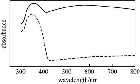
Figure 2 Solid UV-Vis of catalyst7% (by mass) Ag+/TiO2; TiO2

Figure 3 XRD patterns of 7% (by mass) Ag+/TiO2 particles▼ antanse phase
Figure 3 describes XRD pattern of 7% (by mass)Ag+/TiO2composite nanophase catalyst. And the samples were tested by D/max 2500PC X-ray diffractometer. The presence of peaks (2θ=25.2°, 37.7°, 47.9°,54.9°, 62.4°) was regarded as an attributive indicator of anatase which was thought to be the most active phase for photocatalysis. As seen from Fig. 3, part of catalyst sample has changed, from anatase phase into rutile phase. The catalyst is a mix crystal. The research had reported that the mix crystal has high photocatalytic activity [22].
3.2 Influence of suspension turbidity
MB of 20 mg·L-1with pH=10.22 was chosen as the target to be degraded. SOF with 500 roots was selected, and a 300 W lamp was the light source.
In Fig. 4, as the catalyst increased, the degradation efficiency became higher than the initial stage.However, too much addition of catalyst resulted in low specific efficiency of photocatalyst. The best amount of catalyst dosage was 1.167 g·L-1. The liquid containing suspended catalyst particles was turbid, and this added the difficulty of external light penetrating through solution. So the scattered SOFs provided effective photon transmitting channels in solution that increased the catalytic efficiency.

Figure 4 The influence of different catalytic dosage■ 0.500 g·L-1; ● 0.667 g·L-1; ▲ 0.833 g·L-1; ▼ 1.000 g·L-1;1.167 g·L-1; 1.333 g·L-1
3.3 Function of fibers
With Ag+/TiO2catalytic dose at 1.167 g·L-1and other reaction conditions remained unchanged. The factor whether to insert optical-fibers into the liquid medium (to utilize the side-illumination function) or introduce illumination just at the liquid surface (the lamp lights the liquid from the above) is examined.The result was shown in Fig. 5. It shows that putting optical-fibers into the solution improves the degradation efficiency. The degradation efficiency reached up to 97%, nearly 20% than the situation of no fiber. The SOFs successfully convert external light to internal illuminant, and solve the problem of insufficient internal light in solution. For the sewage treatment, especially at some places without light, the SOF system can be used as a reference.

Figure 5 Photocatalytic degradation efficiency of methylene blue with different ways of light delivery into liquid phase■ no fiber; ● fibers
3.4 Quantity of optical-fiber influence
Experiment was also done with the variable quantity of SOFs, while other reaction conditions remained unchanged. Light goes into solution through fibers. The quantity of fiber increased, the capacity of light transport is increased accordingly. On the other hand, light in fibers is subjected to certain attenuation,especially when the length elongates. In other words,increasing fiber number may reduce light attenuation.Under the condition of total light illumination intensity invariable, photocatalytic activity also increases rapidly as the number of optical fiber increased (Fig. 6).Considering the cost of SOFs, the system with 500 roots of SOF attained good degradation efficiency, and thus was selected.

Figure 6 Degradation efficiency of different optical-fiber quantity■ 300 fibers; ● 500 fibers
3.5 Intensity of light influence
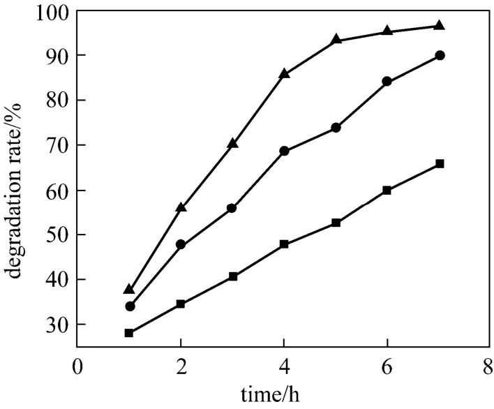
Figure 7 The influence of different light intensity■ 100 W; ● 200 W; ▲ 300 W
Different lamps (100 W, 200 W and 300 W) were chosen for test, while other reaction conditions remained unchanged (Fig. 7). According to the Langmuir-Hinshelwood kinetics, light intensity is correlated with the catalytic efficiency. It is reported [23] that in low light intensity, the degradation efficiency of organic pollutant and light intensity are linearly correlated. In medium light intensity, the decomposition efficiency is linearly related with the square root of light intensity. Further increasing the intensity, photocatalytic reaction becomes gradually irrelevant of the light intensity. In this experiment, light intensity was suitable,and the photodegradation efficiency improved significantly with lamp power. When lamp selected 300 W, the efficiency rate reached 97%. Considering the cost, 300W for this reaction is suitable.
4 CONCLUSIONS
The effect of catalyst dosage, optical-fiber quantity,and some another factors on photocatalytic performance is investigated. Catalyst doped Ag+had good response within visible light which account for 70% in the sunlight. SOF can emanate light from its side uniformly and transmit a longer distance than ordinary quartz optical fiber. Because of its coated layer, it can be freely bent and not easily broken. These characters make SOF much suitable for use in photocatalytic reactor. This work shows that photodegradation which combined Ag+/TiO2and SOFs with visible light for photocatalysis is feasible. And the suitable reaction conditions were 1.167 g⋅L-1Ag+/TiO2with 7% (by mass) of Ag+doped in TiO2, and 500 SOFs in the cross section ofφ10 cm. The photocatalytic degradation efficiency under 300 W lamp illumination was about 97% in 6 h. The degradation efficiency was proportional to SOF quantity, light intensity and catalytic doses within certain ranges. This experiment provides a reference for the treatment of contaminated water in the subsurface environment or dark places without light.
ACKNOWLEDGEMENTS
The authors thank gratefully Mr.Hui Xu and Mr.Wei Zhou for their analytical support.REFERENCES
1 Li, J., Cheng, C., Zhao, J., Zhu, H., Orthman, J., “Photodegradation of dye pollutants on TiO2nanoparticles dispersed in silicate under UV-Vis irradiation”,Appl.Catal.B Envir., 37, 331-338 (2002).
2 Hager, S., Bauer, R., Udilka, G.K., “Photocatalytic oxidation of gaseous chlorinated organic over titanium dioxide”,Chemosphere,41, 1219-1219 (2000).
3 Xie, Y.B., Shen, X.W., Yuan, C.W., “A novel multi-tube photo reactor with UV light and immobilized TiO2thin film for water treatment”,Chin.J.Chem.Eng., 11, 27-32 (2003).
4 Zhu, X.D., Castleberry, S.R., Nanny, M.A., Butler, E.C., “Effects of pH and catalyst concentration on photocatalytic oxidation of aqueous ammonia and nitrite in titanium dioxide suspensions”,Envir.Sci.Technol., 39, 3784-3791 (2005).
5 Lin, Y.M., Tseng, Y.H., Huang, J.H., Chao, C.C., Chen, C., Wang, I.,“Photocatalytic activity for degradation of nitrogen oxides over visible light responsive titania-based photocatalysts”,Envir.Sci.Technol., 40, 1616-1621 (2000).
6 Zhou, Y.S., Jiang, G.W., “Study on properties of composite oxides TiO2/SiO2”,Chin. J. Chem .Eng., 10, 349-353 (2002).
7 Dai, Z.M., Burgeth, G., Parrino, F., Kisch, H., “Visible light photocatalysis by a titania-rhodium (III) complex”,J.Organomet.Chem.,694, 1049-1054 (2009).
8 Sobana, N., Muruganadham, M., Swaminathan, M., “Nano-Ag particles doped TiO2for efficient photodegradation of direct azo dyes”,J.MolecularCatal.A Chem., 258, 124-132 (2006).
9 Rupa Valentine, A., Maniandan, D., Divakar, D., Sivakumar, T.,“Effect of deposition of Ag on TiO2nanoparticles on the photodegradation of reactive Yellow-17”,J.Hazard.Mater., 147, 906-913(2007).
10 Tayade, R.J., Kulkarni, R.G., Jasra, R.V., “Enhanced photocatalytic avtivity of TiO2-coated NaY and HY zeolites for the degradation of methylene blue in water ”,Ind.Eng.Chem.Res., 46, 369-376 (2007).
11 Tsoukleris, D.S., Maggos, T., Vassilakos, C., Falaras, P., “Photocatalytic degradation of volatile organics on TiO2embedded glass spherules”,Catal.Today, 129, 96-101 (2007).
12 Liang, M., Sun, S.Q., Peng, S.C., Chen, T.H., Gan, H., “Study on preparation and improvement of palygorskite-TiO2as a photocatalyst”,J.HefeiUniversityof Technology(Natural Science), 32,145-149 (2009). (in Chinese)
13 Huang, H., Du, Y.K., Dai, J.T., Yang, P., “Prepared of TiO2/ACF catalysts and their photo degradation on tetrachlorethylene”,Photograph.Sci.Photochem., 25, 123-129 (2007).
14 Danion, A., Disdier, J., Guillard, C., Païssé, O., Jaffrezic-Renault, N.,“Photocatalytic degradation of imidazolinone fungicide in TiO2-coated optical fiber reactor”,Appl.Catal.B Envir., 62, 274-281 (2006).
15 Xu, J.J., Ao, Y.H., Fu, D.G., Lin, J., Lin, Y.H., Shen, X.W., Yuan,C.W., Yin, Z.D., “Photocatalytic activity on TiO2-coated side-glowing optical fiber reactor under solar light”,Photochem.Photobiol.A:Chem., 199, 165-169 (2008)
16 Marinangeli, R.E., Ollis, D.E., “Photoassisted heterogenous catalysis with optical fibers (I) Isolated single fiber”,AIChE J., 23, 415-426(1977).
17 Marinangeli, R.E., Ollis, D.E., “Photoassisted heterogenous catalysis with optical fibers (II) Nonisothermal single fiber and fiber bundle”,AIChE J., 26, 1000-1008 (1980).
18 Marinangeli, R.E., Ollis, D.E., “Photoassisted heterogenous catalysis with optical fibers (III) Photoelectrodes”,AIChE J., 28, 945-955(1982).
19 Choi, W.Y., Ko, J.Y., Park, H., Chung, J.S., “Investigation on TiO2-coated optical fibers for gas-phase photocatalytic oxidation of acetone”,Appl.Catal.B Envir., 31, 209-220 (2001).
20 Hyunku, J., Jeong, H., Jeon, M., Moon, I., “The use of plastic optical fiber in photocatalysis of trichloroethylene”,Solar Energy Mater.Solar Cells, 79, 93-101 (2003).
21 Cheng, Y.Q., Li, L.L., Yin, X.M., Xu, J., “Study on phase transformation and bactericidal activity of sol-gel Ag doped titania powders”,Precious Metals, 28, 37-42(2007). (in Chinese)
22 Zhang, F.X., Zhang, X., Chen, J.X., Liu, Z.G., Gao, W.L., Jin, R.C.,Guan, N.J., “Preparation and characterization of Ag/TiO2nanoparticle catalyst and its photocatalytic activity”,Chin.J.Catal., 11,877-880 (2003). (in Chinese)
23 Vinodgopal, K., Kamat, P.V., “Enhanced rates of photocatalytic degradation of an azo dye using SnO2/TiO2coupled semiconductor thin films”,Envir.Sci.Technol., 29, 841-845 (1995).
杂志排行

Chinese Journal of Chemical Engineering的其它文章
- Ammoximation of Cyclohexanone to Cyclohexanone Oxime Catalyzed by Titanium Silicalite-1 Zeolite in Three-phase System*
- Adsorption and Desorption of Praseodymium (III) from Aqueous Solution Using D72 Resin*
- Turbulent Characteristic of Liquid Around a Chain of Bubbles in Non-Newtonian Fluid*
- Isolation and Characterization of Heterotrophic Nitrifying Strain W1*
- Recovery of Tungsten (VI) from Aqueous Solutions by Complexationultrafiltration Process with the Help of Polyquaternium*
- Optimizing the Chemical Compositions of Protective Agents for Freeze-drying Bifidobacterium longum BIOMA 5920*