Service Robot Localization Based on Global Vision and Stereo Vision
2012-02-07YUQingxiao于清晓YANWeixin闫维新FUZhuangZHAOYanzheng赵言正
YU Qing-xiao(于清晓),YAN Wei-xin(闫维新),FU Zhuang(付 庄),ZHAO Yan-zheng(赵言正)*
1 State Key Laboratory of Mechanical System and Vibration,Shanghai Jiaotong University,Shanghai 200240,China
2 State Key Laboratory of Robotics and System,Harbin Institute of Technology,Harbin 150001,China
Introduction
Mobile robot localization and object pose estimation in a working environment have been central research activities in mobile robotics.Solution of mobile robot localization needs to address two main problems[1]:the robotmusthave a representation of the environment;the robot must have a representation of its belief regarding its pose in this environment.Sensors are the basis of addressing both problems.Many of the sensors available to mobile robots are introduced in Ref.[1],giving their basic principles and performance limitations.Based on this introduction,ultrasonic sensors[2,3],goniometers[4],laser range finders[5,6],and charge coupled device(CCD)cameras[7,8]are sensors which are commonly applied in mobile robot localization projects to gather high precision information on the robot's pose estimation.
Most mobile robot localization approaches can be widely classified into three major types:metric,topological,and hybrid.Metric approaches[9,10]are useful when it is necessary for the robot to know its position accurately in terms of metric coordinates.And,the state of the robot can also be represented in a more qualitative manner,by using a topological map[11,12].Butthese methods confrontmany difficulties when the environments are changed.A vision-based localization and mapping algorithm which used scale-invariant image feature(STIF)was applied for mobile robot localization and map building in Ref.[13].Miro et al.[14]used the binocular vision system to generate the disparity map by matching feature and realized the self-localization and self-navigation.Grzyb et al.[15]adopted stereo images and biologically inspired algorithms to accurately estimate the pose,size,and shape of the target object.Greggio et al.[16]applied stereo cameras and a real-time tracking algorithm to realize pattern recognition and evaluate the 3D position of a generic spatial object.Chinellato et al.[17]proposed a visual analysis which was based on a computational model of distance and orientation estimation inspired by human visual mechanisms to extract the features and pose of the object.
Considering the positioning cost and computational efficiency,a hierarchical localization method based on vision is proposed to provide the absolute coordinates in this paper.The proposed algorithm can estimate the real-time coordinates well,and obtain up to±2 cm positioning accuracy to make sure that the robot can successfully grab the object.
1 Hierarchical Positioning Method
1.1 Global vision-based coarse localization
The estimation of the mobile robot's pose is a fundamental problem,which can be roughly divided into two classes[13]:methods for keeping track of the robot's pose and methods for global pose estimation.Most ofthe present research has concentrated on the first class,which assumes that the initial pose of the robot is known[18].In this study,both methods are used to position the mobile robot in the initial stage.The global vision-based localization method is used to calculate the initial position oftherobotand periodically update itscurrent coordinates,and the dead-reckoning method is also used to localize the robot as a supplementary method.In the following part,the global vision-based localization method is explained in detail.
One monocular camera mounted on the ceiling is used to acquire and transmit the global image to the robot through the wireless network.The image is firstly processed to remove the image distortion.Then,color segmentation method is used to position the robot in the image and distinguish the color mark on the head in the Hue-Saturation-Value(HSV)color space.After distinguishing and extracting the color mark,the coordinates of the color mark can be obtained to calculate the coordinates of the robot,according to the global vision model shown in Fig.1.
In Fig.1,(0,0)denotes the origin of the camera coordinate system;HCdenotes the height of the camera relative to the floor;HRdenotes the height of the robot;(XRC,YRC)is the center coordinate of the robot;(XHC,YHC)is the center coordinate of the color mark.
According to the geometric relationship,the following equation can be obtained:

Then,the following results can be calculated as:


Fig.1 The global vision camera model
In Eq.(2),we know that(XRC,YRC)is dependent on the values of HC,HR,and(XHC,YHC).But the values of HCand HRare invariant in this study,and(XRC,YRC)is only dependent on(XHC,YHC).
Four coordinate systems:global coordinate system(GCS),robot coordinate system(RCS),sensor coordinate system (SCS),and virtualglobalcoordinate system(VGCS)[19]are all under consideration.So,the appropriate transformation between VGCS and SCS should be acquired to calculate the absolute coordinates of the robot.According to the geometric relationship in Fig. 1, the homogeneous transformation matrix T between OXYZ and O′X′Y′Z′can be obtained as:

Then,the coordinates of the robot in VGCS can be calculated as:

In the study,VGCS is coincident with GCS in addition to different scale.So,the absolute coordinates of the robot can be achieved as:

where Kheightand Kwidthare the relative scales to the VGCS;m and n are shift distances of VGCS relative to SCS.
In this way,the robot can know its initial position wherever it is placed and periodically update its current coordinates.Furthermore,the real-time positioning of the robot can be realized in indoor environment with the help of the deadreckoning method.
1.2 Stereo vision-based precise localization
When the service robot moves into the area where the object is placed under the guidance of the global vison,the binocular vision-based localization method is adopted to provide high positioning accuracy to successfully grab the object for the customer.In this study,color segmentation and shape-based matching[20]are separately applied to detect the object,and the extracted results are fused to obtain the accurate object.The color segmentation method has been discussed.Below,we describe the shape-based matching method.
The advantage ofshape-based matching isitsgreat robustness and flexibility.Instead of using the gray values,features along contours are extracted and used for the model generation and matching.The method is invariant to changes in illumination and variations of object gray values.The method also allows the object to be rotated and scaled.The process of shape-based matching is divided into two distinct phases:the training phase and the recognition phase.In the first phase,the template model should be created and trained.In the second phase,the model is used to find and localize the object in the image.The basic concept of shape-based image matching is shown in Fig.2.

Fig.2 The basic concept of shape-based image matching
Using the mentioned mehods,the regions of interest(ROI)are seperately obtained. Then,the following information fusion method is adopted to find the expected region of the object.Suppose that image regions A are obtained using color segmentation method and image regions B are also obtained using shape-based matching method.The center points of image regions A and B are all extracted and compared one by one.If the difference between the center coordinates of one A image region and the center coordinates of one B image region is less than the default constant ε,the image area belongs to the expected regions of interest.Otherwise,the image area is the error detected region.Then,the expected regions of interest can be obtained as:

where(xi,yi)is the center coordinates of the sub-region of the image regions A;(xj,yj)is the center coordinates of the j subregion of the image regions B.
According to Eq.(6),the expected regions can be obtained to find and match the object.After obtaining the plate region,the normalized cross-correlation(NCC)matching method[21]is adopted to obtain the depth image.Then,the 3D coordinates of the color mark,which is on the object,can be calculated using the binocular vision system.To localize the mobile robot,the homogeneous transformation matrix between binocular coordinate system and RCS should be firstly obtained.Figure 3 shows the relationship between binocular coordinate system and RCS.

Fig.3 The diagram of binocular coordinate system and RCS
In Fig.3,α and θ are the rotation degrees of the head;O′X′Y″Z denotesRCS,and O″X″Y″Z″ denotesbinocular coordinate system.When α and θ are equal to zero,O″X″Y″Z″shifts negative 6 cm in the X-axis direction relative to O′X′Y′Z′.According to these information, the homogeneous transformation matrix T between O′X′Y′Z′and O″X″Y″Z″can be got as:

Then,the coordinates of the color mark in RCS can be calculated as :

where[x′ y′ z′]Tis the location of the color mark in RCS;[x″ y″ z″]Tis the location of the color mark in binocular coordinate system.
In addition to obtain the 3D coordinates of the color mark,the angle of the object relative to the robot should be also calculated by extracting and filtering the edge lines of the object.Detailed process is as follows.Firstly,the region of the object is processed using the expansion algorithm and canny operator.Then,the extracted edge lines are filtered using the threshold filter to obtain the available edge lines which can denote the angle of the object.Then,the selected edge lines are filtered using the mean filter,which can be used to calculate the angle of the object.Finally,the angle of the object relative to the robot,φobject,can be reckoned as follows.

where φ denotes the detected angle of the object in the image and θ is the rotation angle of the neck joint.
After determining the position of the color mark,the robot can adjust the velocity and heading angle to move towards the object under the guidance of the location-based visual servo control system.Periodically localize the position of the color mark using the method above and adjust the pose of the robot until the robot successfully realizes its precise positioning relative to the color mark.The location-based visual servo control system is shown in Fig.4.

Fig.4 The chart of the location-based visual servo control system
2 Experiments and Result Analysis
2.1 Experiment setup
The experimental platform is a restaurant robot as shown in Fig.5 which is equipped with one binocular camera.The model of the binular camera is bumblebee2 which is made by Point Grey Research.There is a global camera mounted on the ceiling which is used to obtain the whole environmental image.The global images with 768×576 pixels are sent to the mobile robot through the wirless ethernet.The binocular camera mounted on the robot head can send the stereo images with 512×384 piexls to the robot through 1 394 bus.Before the experiment,the binocular camera has been calibrated in advance.
The complete movement of the service robot can be divided into two parts:coarse localization and precise localization.In the following parts,we explain the experimental results of the complete movement from the two aspects.

Fig.5 The photo of the restaurant service robot
2.2 Global vision-based coarse localization
In this part,the global vision localization method can be explained through the following example in this study.The mobile robot receives the image of the restaurant from the global camera through the wirless ethernet.To acquire the available value from the image,we should firstly rectify the raw image.Figure 6 is the rectified global image obtained from the camera.To localize the robot in the image,we should find the ROI and detect the color mark on the robot head using the color segmentation method.The result of the image processing is shown in Fig.7.

After the location of the robot is detected in the image,the location of the robot relative to the pinhole camera coordinate system should be calculated.We have known the size of the picture in advance.And the height of the camera relative to the floor and the height of the robot are invariant and also known in advance.Because the position and the parameters of the global camera are invariant,the scales of the pixel relative to the one centimeter in the X-axis and Y-axis directions can be acquired.These parameters which are used to calculate the location of the robot,are all shown in Table 1.

Table 1 The used parameters in this experiment
In Fig.7,the origin of the picture coordinate system is in the top left-hand corner of the picture.And the coordinates of the color mark in the picture coordinate system have been calculated.According to Fig.1,we obtain the transformation coordinates,(X'HC,Y'HC),in the pinhole coordinate system.Then,the result can be calculated as(-68.50,- 311.33).After(X'HC,Y'HC)is obtained,the robot can be positioned in the image as(-39.14,-177.90).
Next,the real coordinates of the robot in GCS should be reckoned.The origin of GCS is in the top right-hand of the carpet array shown in Fig.7.And,the coordinates of the top right-hand of the carpet array is(216,237)in the pinhole coordinate system.So,the coordinates of the robot in GCS is calculated as
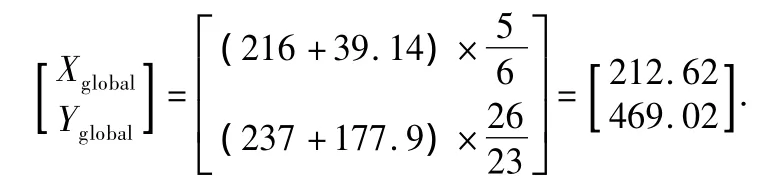
Many experiment results show that the accuracy of global vision positioning is within ±7 cm.In this study,the coordinates of the robot is updated every 100 ms to make sure that the robot can obtain its real-time coordinates.
2.3 Stereo vision-based precise localization
When the robot moves into the area where the object is placed under the guidance of the global vison,the stereo visionbased localization method is adopted toprovide the high positioning accuracy.The acquired images from binocular camera are firstly rectified using image correction algorithm to prepare the available images for the next process.The rectified image from the stereo vision during the robot movement is shown in Fig.8.

Fig.8 The rectified stereo vision image
In this study,the image taken by the right camera is used as the reference image where the ROI is extracted to realize the object feature matching and obtain the disparity map of the object.The object region is detected and extracted using color segmentation and shape-based matching methods.The procedure of color segmentation is as follows.Firstly,HSV color spaces could be obtained through the image color space conversion.Then,the appropriate thresholds are set in the Hue and Saturation space components.Finally,the plate region is extracted from the reference image.And the plate region can be also found in the image using the shape-based matching method.Each center coordinates of the extracted regions of interest can be firstly extracted,then,the expected region can be obtained according to Eq.(6).The plate region in Fig.9 is the expected region which is obtained according to the methods above.

Fig.9 The expected region of interest
Next,we should find the characteristic sign in the expected region and match image using NCC algorithm.In the process,the consistency test between the left and right images is also used to find the accuracy matching.The obtained depth image is shown in Fig.10.
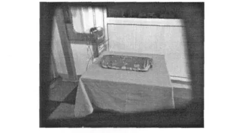
Fig.10 The obtained depth image using NCC
From Fig.10,we can know that the depth value of the characteristic sign is 40.07.According to the binocular vision system,the coordinates of the characteristic mark can be calculated as[1.4 0.2 118.9]T.Otherwise,using the encoders,we can know that α =45°and θ=0°.Then,using Eq.(7),the homogeneous transformation matrix T,between RCS and binocular vision coordinate system is denoted as follows:

Finally,according to Eq.(8),the result can be reckoned as[x′ y′ z′]=[- 4.6 88.5 83.9].Otherwise,the angle of the object relative to the robot should be calculated to determine the position of the color mark.In experiment,firstly,the edge lines of the object are extracted using canny operator.Then,the extracted edge lines are filtered using the threshold filter to find the available lines.Finally,the selected lines are filtered using the mean filter to calculate the angle of the object.The obtained lines using the method above are shown in Fig.11.From Fig.11,we know that the angle of the object is-3.865°.

Fig.11 The extracted edge lines of the object
After determining the position of the color mark,the robot can adjust the velocity and heading angle to move towards the object under the guidance of the location-based visual servo control system.And in the process of the movement,the robot should constantly repeat the positioning process above and adjust its pose until the precise positioning is finally realized.
We performed the whole movement at the velocity of 0.15 m/s for sixty times in our library,and the initial position of the robot was random and unknown each time.And,the service robot could always realize self-localization with the positioning accuracy up to±2 cm and successfully grab the object for the customers within 3 min.The statistical data are shown in Table 2.

Table 2 The application and positioning accuracy of the hierarchical localization method
3 Conclusions and Future Work
In this paper,a method of mobile robot localization which is based on visual feedback is proposed and applied on the restaurant service robot.The whole positioning process can be divided into two stages:coarse positioning and precise positioning.Hierarchical positioningmethod is adopted to provide different positioning accuracies in different stages.In the coarse positioning stage,the robot can periodically obtain its current coordinates using the global vision-based localization method.In the precise positioning stage,the robot can obtain higher localization precision using the binocular vision-based localization method.Finally,the robot can successfully grasp the plate on the table.Many experiments verify that the proposed algorithm has good location effect and obtains up to±2 cm positioning accuracy.
Currently,research on the improvement in the positioning accuracy and speed of the algorithm is under way.And our future work will also focus on improving the anti-interference ability to the more complex environment.
[1]Siegwart R,Nourbakhsh I.Introduction to Autonomous Mobile Robots[M].Cambridge:The MIT Press,2004:121-156.
[2]Choi B S,Lee J J.Mobile Robot Localization Scheme Based on RFID andSonarFusion System [C].IEEE International Symposium on Industrial Electronics,Seoul,Korea,2009:1035-1040.
[3]Choi B S,Lee J J.Localization of a Mobile Robot Based on an Ultrasonic Sensor Using Dynamic Obstacles[J].Artificial Life and Robotics,2008,12(1/2):280-283.
[4]Bonnifait P,Garcia G.Design and Experimental Validation of an Odometric and Goniometric Localization System for Outdoor Robot Vehicles[J].IEEE Transactionson Roboticsand Automation,1998,14(4):541-548.
[5]Balaguer B,Carpin S,Balakirsky S. Towards Quantitative Comparisons of Robot Algorithms:Experiences with SLAM in Simulation and Real World Systems[C].IEEE/RSJ International Conference on Intelligent Robots and Systems,California,USA,2007:1-7.
[6]Lin H H,Tsai C C.Laser Pose Estimation and Tracking Using Fuzzy Extended Information Filtering for an Autonomous Mobile Robot[J].Journal of Intelligent and Robotic Systems,2008,53(2):119-143.
[7]Munguia R,Grau A.Monocular SLAM for Visual Odometry[C]. IEEE InternationalSymposium on IntelligentSignal Processing,Madrid,Spain,2007:1-6.
[8]Lin H Y,Lin J H,Wang M L.A Visual Positioning System for Vehicle or Mobile Robot Navigation[C].Proceedings of the 8th InternationalIEEE Conference on Intelligent Trasportation Systems,Vienna,Austria,2005:73-78.
[9]Blanco J L,Gonzalez J,Fernandez-Madrigal J A.Consistent Observation Grouping for Generating Metric-Topological Maps that Improves Robot Localization[C].Proceeding of IEEE International Conference on Robotics and Automation,Orlando,USA,2006:818-823.
[10]Guo Y,Xu X H.Color Landmark Design for Mobile Robot Localization[C].IMACS Multiconference on Computational Engineering in Systems Applications,Beijing,China,2006:1868-1874.
[11]Kwon T B,Yang J H,Song J B,et al.Efficiency Improvement in Monte Carlo Localization through Topological Information[C].Proceeding of 2006 IEEE/RSJ International Conference on Intelligent Robots and Systems,Beijing,China,2006:424-429.
[12]Tapus A,Siegwart R.A Cognitive Modeling of Space Using Fingerprints ofPlaces for Mobile Robot Navigation [C].Proceedings of the IEEE International Conference on Robotics and Automation,Orlando,USA,2006:1188-1193.
[13]Borenstein J,Everett B,Feng L.Navigation Mobile Robot:System and Techniques[M].Wellesley,USA:A.K.Peters Ltd.,1996:103-150.
[14]Miro J V,Zhou W Z,Dissanayake G.Towards Vision Based Navigation in Large Indoor Environments[C]. IEEE International Conference on Intelligent Robots and Systems,Beijing,China,2006:2096-2102.
[15]Grzyb B,Chinellato E,Morales A,et al.A 3D Grasping System Based on MultimodalVisualand TactileProcessing [J].Industrial Robot:An International Journal,2009,36(4):365-369.
[16]Greggio N,Bernardino A,Laschi C,et al.Real-Time 3D Stereo Tracking and Localizing of Spherical Objects with the iCub Robotic Platform [J].Journal of Intelligent and Robotic Systems,2011,63(3/4):417-446.
[17]Chinellato E,Grzyb B J,del Pobil A P.Brain Mechanisms for Robotic ObjectPose Estimation[C]. InternationalJoint Conference on Neural Networks,Hong Kong,China,2008:3268-3275.
[18]Lang H X,Wang Y,de Silva C W.Mobile Robot Localization and Object Pose Estimation Using Optical Encoder,Vision and Laser Sensors[C].Proceedings of the IEEE International Conference on Automation and Logistics,Qingdao,China,2008:617-622.
[19]Yu Q X,Yuan C,Fu Z,et al.Research of the Localization of Restaurant Service Robot[J].International Journal of Advanced Robotic Systems,2010,7(3):227-238.
[20]El Munim H A,Farag A A. Shape Representation and Registration Using Vector Distance Functions[C].Proceedings of theIEEE Conference on ComputerVision and Pattern Recognition,Minneapolis,USA,2007:1-8.
[21]Sun Z X,Wu Q.TS201 Based Fast Algorithm of Normalized Cross-Correlation[J].Modern Electronics Technique,2010,33(10):125-127.(in Chinese)
杂志排行

Journal of Donghua University(English Edition)的其它文章
- Frost Resistance and Damage Velocity of Compressively Preloaded Concrete
- Vehicle OHT DispatchingPerformance Analysis ofan AMHS in 300mm Semiconductor FABs
- Research on Cooperation Mechanism ofChina'sFinancialRegulation and Supervision System
- Determination of the Dose of PAC in Ultrafiltration System for Drinking Water Treatment
- Hydrophobic TixOy-CmHnNanoparticle Film Prepared by Plasma Enhanced Chemical Vapor Deposition
- Comparison and Analysis of Fabric Deodorization Test Methods