端墙形状对蒸汽涡轮效率的影响
2011-12-02HoznedlMichalTajcLadislavBednarLukasDvorakDalibor
Hoznedl Michal Tajc Ladislav Bednar Lukas Dvorak Dalibor
(1.斯柯达动力公司实验研究部,皮尔森,捷克;2.西波黑米亚大学动力系统工程系,皮尔森,捷克)
Nomenclature
b/mm Chord
c/(m◦s-1) Absolutevelocity
D/mm Diameter
l/mm Length
R/mm Radius
w/(m◦s-1) Relative velocity
z Number of blades
T,U/(°) Angles
Δl/mm End-wall enlargement
ΔL/mm Affected length
X Admission ratio Sadm/Sfull
Z Efficiency derived from temperatures
k/(rad◦s-1) Circumferential velocity
Y Pressure loss coefficient
Subscripts
ax Axial
h Hub
is Isentropic
s Static conditions,stator
u Circumferential
1 Inlet conditions
2 Outlet conditions
INTRODUCTION
There are a number of theories for limiting end-wall loss in the turbine stage and optimizing flow in blade cascades.Many of these theories include shaping of the hub and tip of the end-wall.In the 1960s,several papers looked into the topic of optimization of the end-wall tip shape[1-2].These studies indicated that an efficiency increase ofΔZ> 1% might be expected in cascades of an aspect ratio of l/b<1.Owing to the more complex technology required for their manufacture,turbine cascades with end-wall shaping cannot enter into practice until several decades later.Progress in profile design optimization shows a reaction to 3-D flow and the limiting effects of end-wall loss results in the contemplation of new experiments with end-wall shaping of the stage tip end-wall.
The topic of shaping the tip end-wall in both the axial and tangential directions were studied in Refs.[3-6].Theinitial theory concept uses shape modifications to influence the pressure distribution on the end-wall in order to reduce the effect of end-wall loss.Though the effect on the efficiency is insufficient compared with other approaches, no other papers focusing on this methodology are published.
During the development of the steam turbine with the radial control stage following by axial stages and with the fully scalable partial admission,a discussion was conducted in terms of the reducing end-wall loss by the symmetrical rendition of shape modifications in both end-walls.VZLU (Aeronautical Test and Research Institute,Prague,Czech Republic)carried out measurements of profileloss in thebladecascade with prismatic and shaped blades.Fig.1 indicates the major reduction of profile-based loss after the shape of walls is modified.New profiles were originally designed for the radial stage,and these profiles were analyzed in the arrangement of the axial blade cascadein the VZLU wind tunnel[7].
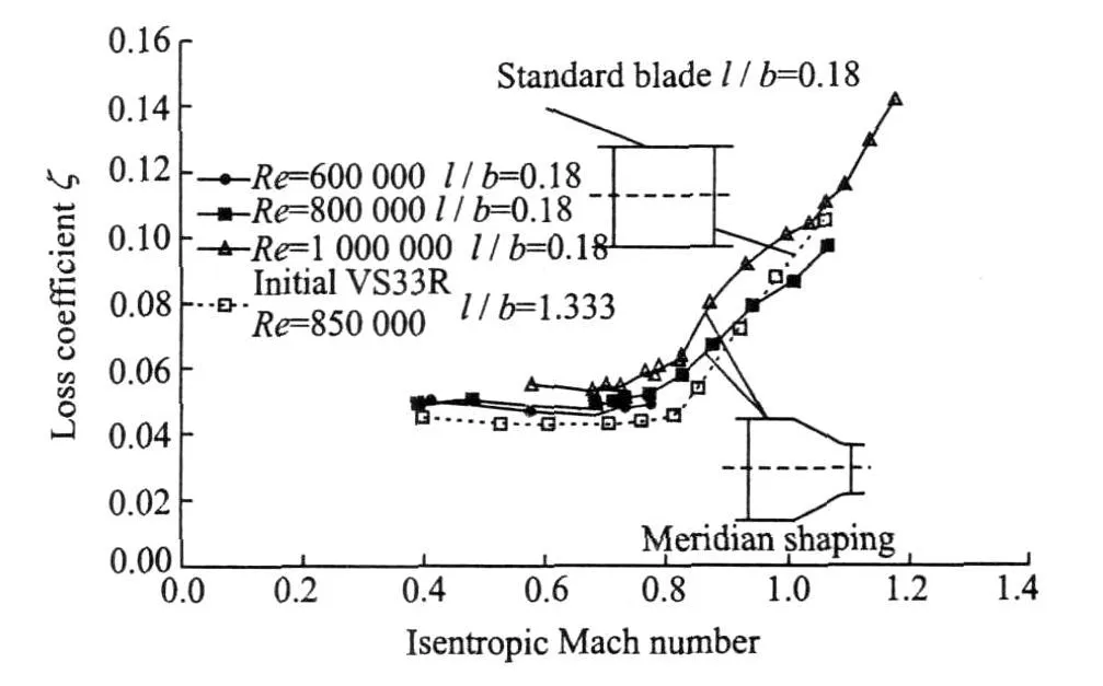
Fig.1 Effects of end-wall shaping on profile loss
Computations were used to estimate the loss for radial design of the blade cascade[8].The result of this approach is shown in Fig.2.Based on the optimistic findings of the blade cascade measurements,an axial turbine blade cascade is designed with bilateral end-wall shaping of the endwalls.The West Bohemia University in Pilsen was commissioned to perform a computational study of 3-D flow in the impulse turbine stage with various arrangements of the end-walls[9-12].Theaim of both thecomputational and the experimental studies is to establish whether the findings of themeasurements in the bladecascade can also be applied in the axial turbine stage.
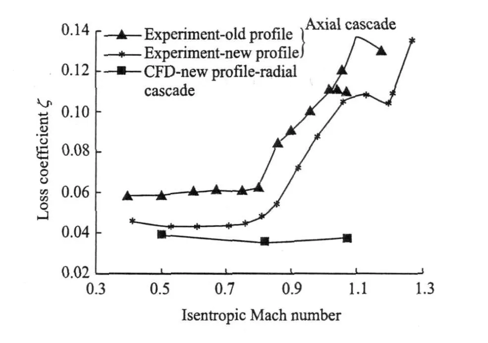
Fig.2 Losses in original and new designs of blade cascade
1 SELECTION OF COMPUTATIONAL MODEL
Three variants of the blade channel in the stator section of the turbine stage are selected for the computational study.The same stage is used in experiments as a second stage of two-stage drum rotor in Section 3.1. The characteristic properties of these variants are indicated in Fig.3.All of thevariants operate with an identical aspect ratio and the identical setting of boundary conditions.The length of channel inlet and outlet are 40 and 50 mm,respectively.The effect of steam leakage through the seals is neglected.The inlet and outlet parameters are taken from experimental results on a steam turbine as well as geo-
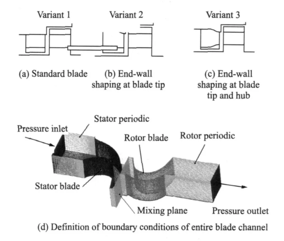
Fig.3 Characteristic properties of variants
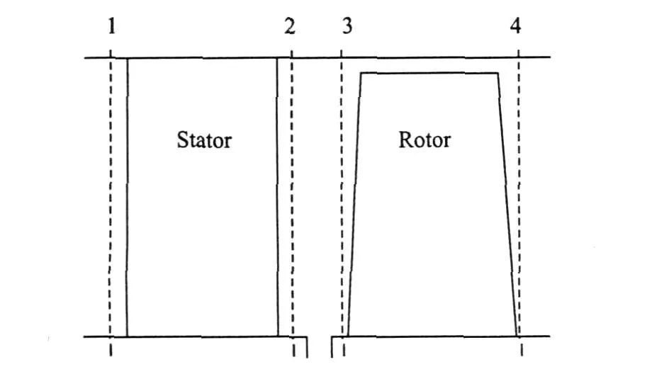
Fig.4 Evaluation planes
2 EVALUATION OF COMPUTED AERODYNAMICS PROPERTIES
Individual variants differ in the arrangement of the boundary sections of the stage.Therefore,assumptions may be drawn that in the mean radius wherea 2-D nature of flow prevails,the loss meets the expectations as to profile loss,and all flow parameters are largely similar in all thevariants.The vectors of absolute velocities at the mean radius of Variant 1 are shown in Fig.5.Maximum velocities are presented behind the leading edge of rotor blade in the profile of the blade suction side.The inlet and outlet velocities of the stage are approximately equal.The outlet angle T2 at a given circumferential velocity of k=377 rad/s is just below 90°.
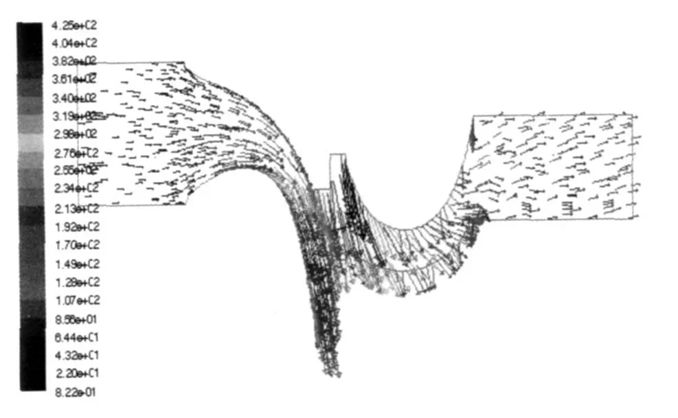
Fig.5 Vectors of absolute velocities at mean radius of Variant 1
The distributed mean values of the axial velocity c2ax along the radial are shown in Fig.6.
The enlargement of the inlet section causes a reduction of inlet velocity and an increase of static pressure due to the end-wall shaping results.Shape modifications of the end-walls lead to velocity increment in the boundary areas of the outlet from the stator blade cascade.The distribution of axial velocity at the inlet into the rotor blade cascade is wavy,which is nearly edged development.The reasons for this remain unclear.A more in-depth analysis of the numerical simulation is required to deliver an explanation.The mean valueof the axial velocity has a slight drop,and a reduction of static pressure is recorded.This is contradicted by the preservation of equality in mass flows.
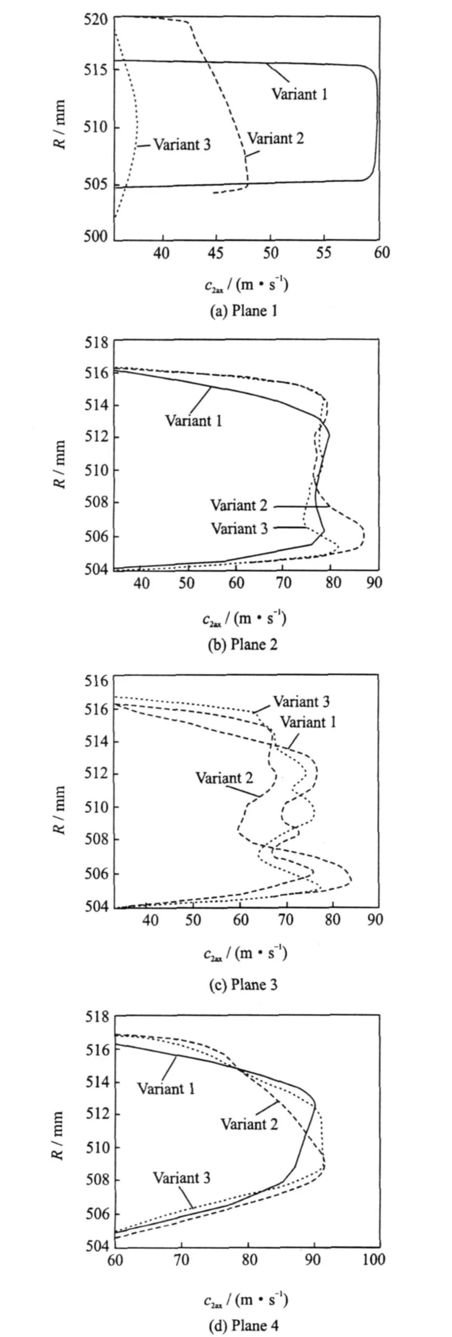
Fig.6 Distribution of velocity axial components
The stage outlet shows the full velocity reduction at the wall area.The rotor cascade exhibits a much higher degree of end-wall loss than the stator section of the stage.The stator influence affects sectionΔL which is in relation to the chord b1,i.e.,ΔL 1/b1= 9%,whereas the rotor delivers as much asΔL2/b2=30%.Based on the preservation of the mass flow,the steam flow inhibition from the boundary sections of stage also indicates the certain improvement of flow conditions in the central section of the stage.Local increments of velocity lead to a local improvement in efficiency.The manner of loss evaluation used in computations does not allow the energy balance along the streamlinewhich is necessary for agood understanding of flow behavior.
The distributions of static pressure P s1,P s2,P s3,P s4 in the individual stage planes are shown in Fig.7.The change of the pressure distribution character at the transition from Plane 2 to Plane 3 is completely inexplicable.Plane 2 has the pressure rising from the hub towards the tip,which meets the experiment findings in full.Pressure distribution in Plane 3 cannot be applied for computation of the stage response.Pressure changes at the stage outlet areirrelevant.The reason may be that Plane 3 is very close to the mixing plane surface and the flow is affected by averaging its parameters on this surface.The pressure distribution in Plane 4 is undoubtedly affected by the computational boundary condition, where the pressure is entered as a constant value for the whole of the plane.Please note that this assumption is in line with the findings of experiments conducted in various stages of power plants.
The loss coefficient or the efficiency value is important in determining the stage or the cascade quality,respectively.The loss distribution in the stator cascade for theindividual variants is shown in Fig.8.Thebest results areindicated in Variant 2,i.e.,the stage with shaping of the end-wall tip.While the shaping of the hub and tip wall delivers an improvement in the boundary areas of the cascade,it has a negative influence on the central section of the channel.All the variants have the greatest loss at the end-walls.This is caused by the presence of the boundary layer and by the flow phenomena in thegiven cascade area.Variant 2 indicates zero loss in the center of the channel.This value is fictitious.All locations of the profile have boundary layers and wake.The zero loss can only be explained as an influx of energy from other cascade areas.
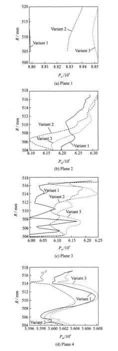
Fig.7 Static pressuredistribution

Fig.8 Stator loss
The stage efficiency for particular stages is shown in Fig.9.According to an identical aspect ratio,the efficiency by using end-wall shaping at the tip and hub has an increase of 0.7%in comparison with standard shaped prismatic blades(Variant 1).When the shaping only affects the tip,the efficiency values increase by more than 0.4%. Considering the low chord value,the Reynolds number is also low(Re=2×10⁵).The results are on the basis of numerical computation with the boundary conditions taken from experimental data.
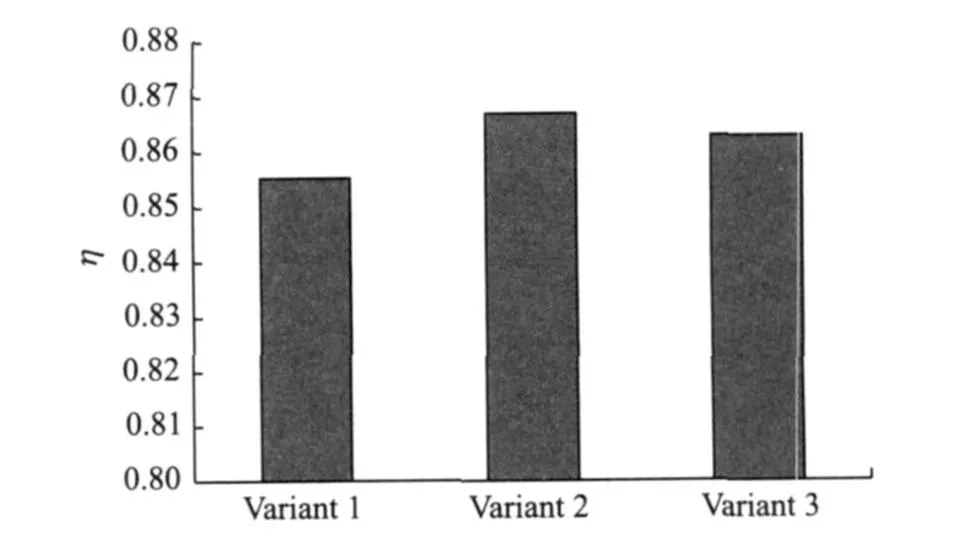
Fig.9 Stage efficiency
The turbine stage efficiency of experiment depends on Re in this area.Thecomputation with Re=1×10⁶and a prismatic blade shows an efficiency of Z=90.22% due to a higher Reynolds number.An experiment with an identical blade design and operation parameters indicates a maximum efficiency of Z= 89.52% when optimal u/cis=0.48.The loss values exceeding the calculation are attributed to the steam leakage through the stator seal.
3 EXPERIMENTAL INVESTIGATION OF TURBINE STAGES
3.1 Experimental stage f or drum rotor
A two-stage impulse drum turbine rotor is designed to conducte the experiment.The first turbine stage uses end-wall shaping elements of the hub and tip end-walls.Fig.10 shows a crosssection view of a drum rotor with notable endwall shaping in the first stage.The basic characteristics of the blade cascades in both stages are shown in Table 1.
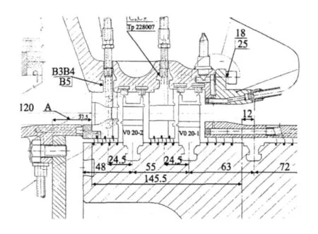
Fig.10 Two-stage drum type turbine
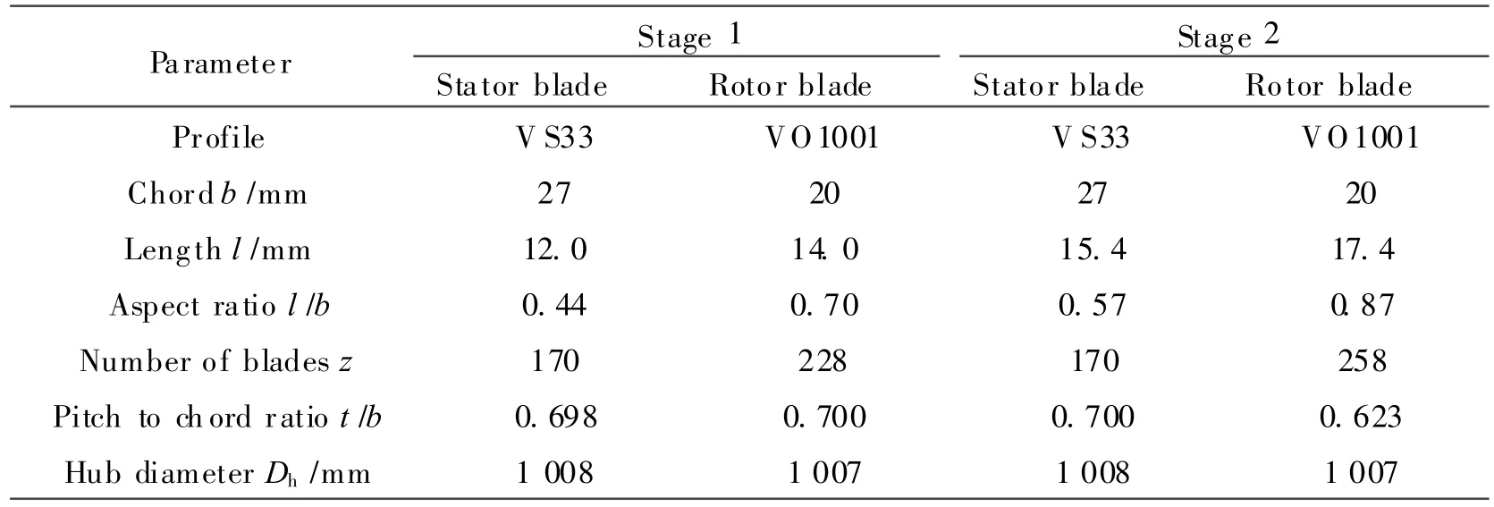
Table 1 Stage parameters
These are impulse stages for subsonic flow.Instead of equalizing holes used in wheel discs,this design uses slots below the rotor blades.The inlet pressure is P1≈0.8 bar and the inlet temperature t1≈ 150°C.The typical pressure drop in the stages is P2/P1≈0.7.The search is for the optimum velocity ratio,u/cis,where the turbine is operated with the maximum efficiency.
The measurement is taken at an experimental steam turbine designed for operation with the admission pressure under the barometric pressure.The energy is marred with a water brake.Due to the reason of measuring in lower pressure,Re is lower than that in real-life installations.During the low values of Re and the identical stage geometry,the efficiency is lower than that in real-life installations.
3.2 Experimental results of drum rotor
The results are focused on the first stage of experimental steam turbine with the end-wall shaping.Fig.11illustrates the dependence of efficiency with the velocity ratio.The efficiency value of the first stage amounts to 0.746 when u/cis=0.47.Re is 2.9×10⁵at the maximum u/cisratio.Re at the numerical simulation described in the preceding section only reaches 2×10⁵,so the efficiency is even slightly lower.However,the difference between this experiment and the numerical simulation(Fig.9,Variant 3)is caused by the fact that the numerical simulations do not include any modeling of the seals at all.Steam leakages play a crucial role,especially in short blade designs.Numerical simulations on higher levels of Re aremade.Experiments show a higher influence of Re compared with computations.
The notable effect of Re on efficiency is proven by Fig.12.Operational reasons prevent the experiment from conducting major changes of Re.However,the evidence indicates that even a small scale of Re lead to an efficiency increase of more than 5%.Theinfluence of a low Re on endwall shaping cannot be proven by the measured results.
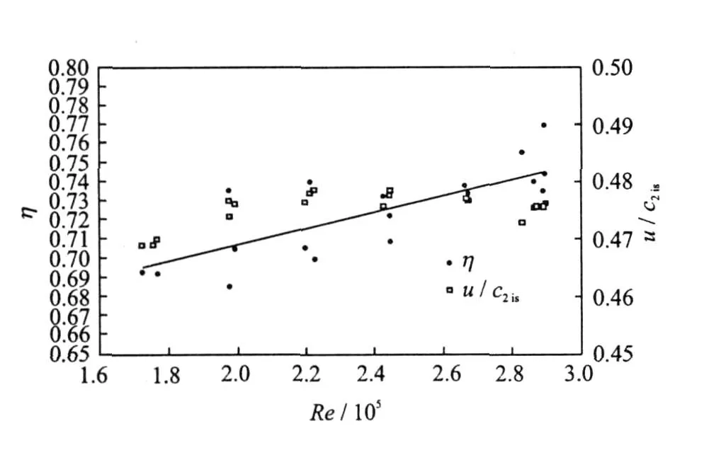
Fig.12 Relationship between efficiency and Reynolds number
The same chart also shows changes of u/c is,which is kept as much constant during the whole experiment if the experimental device allows.Minor differences are caused by experimental possibilities and they do not have a significant influence on the results.The Mach number is constant during both the measurements. Therefore,its impact on efficiency may be excluded as well.The influence of Re on efficiency is significant.The effect of the end-wall shaping is impossible to segregate from other effects in this measurement.
3.3 Experimental stage f or disc rotor
The structure of the experimental stage is shown in Fig.13.The basic technical specifications of the blade section are provided in Table 2.The geometry of the stage is the same as that in the numerical computations,Variant 2,therefore,without shroud seals.
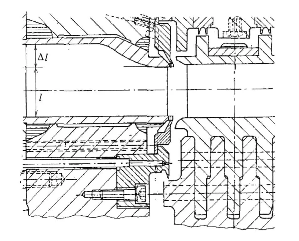
Fig.13 Geometry of disc rotor stage
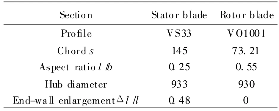
Table 2 Stage geometry
3.4 Experimental results of disc rotor
Compared with the reference blades without end-wall shaping,no further reduction of loss in end-wall shaped stage is confirmed.The observation of Fig.14 suggests that there even is a minor aggravation.The value of X=1 indicates the full admission of the stage.The value of Z Nmax means the maximal efficiency level reached by using the standard blades experiment.The modifications of the original old profiles focus on reducing theprofile and end-wall loss.The one end-wall shaping does not guarantee the stage efficiency improvement coming from the new profiles.However,the result includes the improvement of the stage reaction and the flow coefficient. The higher mass flow of steam through the stage allows increasing the output.The application of end-wall shaping in stages with the partial admission of steam is highly promising.A comparison of the efficiency to the typical stage design is shown in Fig.15.In total admission,the efficiency hardly has any improvement.However,in the case of partial admission,the efficiency increases by as much as 10%.
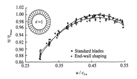
Fig.14 Effects of end-wall shaping on steam turbine efficiency
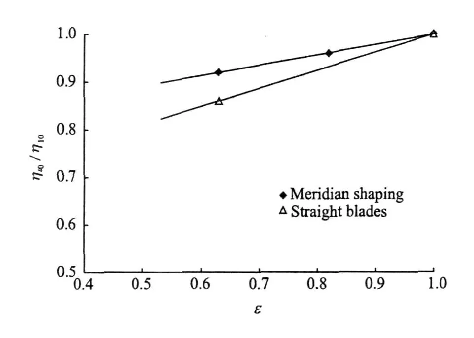
Fig.15 Comparison of stage efficiencies
4 CONCLUSIONS
(1)The numerical simulation of the impulse stage is performed with the same geometry as the experimental stage.
(2)Three alternatives of end-wall shaping are tested by using CFD methods.
(3)The computational study confirms the reduction of boundary loss in the turbinestageafter the application of end-wall shaping in the endwalls.Shaping the end-wall tip delivers better results than shaping both sides.
(4)The difference between the efficiency determined by the experimental measurement and the numerical computations is caused by the significant influence of the shroud seals used in the experiments only.Numerical simulations do not exactly describe the influence of the Reynolds number.The experiments show a higher effect of Reynolds number than computations.
(5)The rotor cascade exhibits a much higher degree of end-wall loss than the stator section of the stage.
(6)The low value of the Reynolds number has a negative influence on efficiency.The effect of the Reynolds number on the end-wall shaping cannot be proven.
(7)End-wall shaping play a rolein partial admission.In full admission,this design seems unsuitable for the future works.
ACKNOWLEDGEMENT
The authors of this paper wish to thank the Ministry of Industry and Trade of the Czech Republic for thefinancial support of Grant No.FT-TA2/037.
[1] Dejc M E,Zarjankin A E,Filipov G A,et al.Methods of efficiency increasing for turbine stages with relatively short blades[J].Teploenergetika,1960,2:18-24.(in Russian)
[2] Dejc M E. Technical aerodymics of gases[M].SNTL:Praha,1967.(in Czech)
[3] Yan J,Gregory-Shmith D G,Ince N Z.Profiled end-wall design for a turbine nozzle row[C]//3rd European Turbomachinery Conference,C557/060/99.London,UK:Proffesional Engineering Publishing,1999:453-464.
[4] Ingram G L,Gregory-Smith D G,Rose M G,et al.The effect of end-wall profiling on secondary flow and loss development in a turbine cascade[C]//ASME Torbo Expo.Amsterdam,The Netherlands:ASME,2002:GT-2002-30339.
[5] Sauer H,Muller R,Vogeler K.Reduction of secondary flow losses in turbine cascades by leading edge modifications at the endwall[J]. Journal of Turbomachinery,Transactions of the ASME,2001,123:207-213.
[6] Funazaki K,Endo T,Tanuma T.Reduction of secondary flow effects in a linear cascade by use of an air suction from the endwall[C]//ASME Torbo Expo.[S.l.]: ASME,1996:96-GT-51.
[7] Benetka J,Valenta R.Measurement of cascade V S33RZ with meridional shaping[M]. Czech:VZLU,2003.(in Czech)
[8] Stastny M,Babak M,Valenta R.Radial high velocity profile cascade for a steam turbine[C]//Colloquium Fluid Dynamic 2004.Prague: ASCR,2004:185-188.
[9] Juza Z,Tajc L,Polansky J.Numerical simulation of the steam flowing through axial turbine stage with modification—Meridian shaping No.1[R].Research Work VZTP 0953,2004.(in Czech)
[10]Juza Z,Tajc L,Polansky J.Numerical simulation of the steam flowing through axial turbine stage V S33—Prismatic blade [R]. Research Work VZTP0948,2004.(in Czech)
[11]Juza Z,Tajc L,Polansky J.Numerical simulation of the steam flowing through axial turbine—Comparison of all computed alternatives of the stage V T2[R].Research Work V ZTP0961,2004.(in Czech)
[12]Dvorak D.Comparison of turbine stage efficiency with relatively small l/b ratio with different shaping of the end walls[D].Pilsen,Czech Republic:Westbohemian University,2005-2006.(in Czech)
杂志排行

Transactions of Nanjing University of Aeronautics and Astronautics的其它文章
- 拉压、扭转载荷下铸铝合金的亿周疲劳性能研究
- 法国MBDA爆震和连续爆震波发动机的研发
- 使用液态化学循环的高热效率动力研究
- FATIGUE LIFE PREDICTION METHOD FOR IMPACTED LAMINATES
- EXPERIMENTAL STUDY OF FORCED SHOCK TRAIN OSCILLATION IN ISOLATOR UNDER ASYMMETRIC INCOMING FLOW
- VIBRATION NUMERICAL ANALYSISOF COUNTER-ROTATING TURBINE WITH WAKE-FLOWUSING FLUID-STRUCTURE INTERACTION METHOD