EXPERIMENTAL STUDY OF THE NON-DARCY FLOW AND SOLUTE TRANSPORT IN A CHANNELED SINGLE FRACTURE*
2011-05-08CHENZhouQIANJiazhongQINHua
CHEN Zhou, QIAN Jia-zhong, QIN Hua
School of Resources and Environmental Engineering, Hefei University of Technology, Hefei 230009, China, E-mail: chenzhoucly@163.com
EXPERIMENTAL STUDY OF THE NON-DARCY FLOW AND SOLUTE TRANSPORT IN A CHANNELED SINGLE FRACTURE*
CHEN Zhou, QIAN Jia-zhong, QIN Hua
School of Resources and Environmental Engineering, Hefei University of Technology, Hefei 230009, China, E-mail: chenzhoucly@163.com
(Received April 3, 2011, Revised August 18, 2011)
The characterization of fracture rocks is always a key issue in understanding the flow and solute transport in fractured media. This article studies the solute transport in a Channeled Single Fracture (CSF), a single fracture with contact in certain areas. The flow in a CSF often has preferential pathways and the transport in a CSF often has Break Through Curves (BTCs) with long tails. The Surface Contact Ratio (SCR), the ratio of the contact area to the total fracture area, is an important indicator for the fracture surface roughness. To study the flow and solute transport in a CSF, a controlled physical model is constructed and a series of flow and tracer test experiments are carried out. Under our experimental conditions, the flow in a CSF is found to follow the Forchheimer equation J =av +bv2, where J and v are the hydraulic gradient and the average pore velocity, respectively and a and b are two parameters related to the viscous and inertial flow components, respectively. Furthermore, it is found that b decreases with the decrease of SCR. For the solute transport, it is found that the BTCs often deviate from the traditional Fickian behavior, by the early-arrival and the long tailing. More interestingly, the observed BTCs often have a double-peak or a multi-peak, that would be difficult to explain using the existing transport theory such as the Advection-Dispersion Equation (ADE). In addition, the longitudinal dispersion coefficient DLis found to be scale-dependent in a CSF and the DL-l relationship is of exponential type.
channeled single fracture, surface contact ratio, non-Darcian, non-Fickian
Introduction
For many decades, the flow and transport in fractured media have been intensively studied because of its importance in many applications such as water resource management, nuclear waste disposal, thermal energy production, and CO2sequestration[1,2], where the characterization of the fracture media is often the first and probably the most important step.
The simplest model of a single fracture is a pair of smooth, parallel plates, and the flow in such a single fracture is often described by Darcy’s law (or the Local Cubic Law (LCL) if the total flow rate is of concern)[3-5]. In reality, the surfaces of naturally formed fractures are rough, unparallel and the fracture surface may be partially blocked by filling materials or closed under a normal stress[6]. Non-Darcy and non-LCL flows found in rough fractured models may be caused by the heterogeneity of fractured media[6-8]. Field and experimental observations show that the flow in such fractures often takes place in only a few channels occupying 5%-20% of the total fracture surface area[9]. For the solute transport in porous media, the Advection-Dispersion Equation (ADE), based on Fick’s law, is usually applied, which means that the dispersive mass flux is proportional to the concentration gradient. This law is also applied for the transport in single fractures in many investigations. However, many features of the transport in a single fracture revealed in extensive studies cannot be explained by the Fickian transport model[10]. First, the peak of the Break Through Curves (BTCs) arrives earlier than what is expected from the ADE (the early arrival), second, the tailing of the BTC lasts much longer than what is expected (the long tail)[11]. In addition, the observed multi-peak of the BTC has not found a satisfactory explanation[12]. Many physical and numericalmodels were established to explain these points[6-8,13]. Among them, Tsang and Tsang (1987) and Tsang and Neretnieks (1998) put forward the concept model of the “Channeled Single Fracture (CSF)” to analyze the physical structure and the solute transport in the channel flow through natural fractures[13]. The CSF model can be employed for both a single fracture and a fracture network in describing the abnormal shape of the BTC and the multi-peak phenomenon[14]. The Surface Contact Ratio (SCR) is taken as the ratio of the contact area to the total fracture area, and it is an important indicator reflecting the fracture surface roughness. The fragmentation degree intensifies with the increase of the stress, which would mean the increase of the SCR[10]. Wu and Zhou[15]concluded that the solute transport in the fracture was controlled strictly by the SCR of the parallel plate.
Further work is needed to reveal the non-Darcy and non-Fickian phenomena in a CSF such as details of the fluid flow and the description of the non-Fickian solute transport. Consequently, a well controlled physical model of the CSF is designed and experiments on the flow and solute transport are carried out in this article.
1. Theoretical background
1.1 Darcy or non-Darcy flow in a CSF
The Reynolds number (Re) here is defined as

where e is the average aperture, v is the average velocity, v = Q /(A × SCR), where Q is the total flux of the flow and A is the cross-section area and μ is the kinematic viscosity of water.
The Darcy law for the flow in a CSF is

where J is the hydraulic gradient, K is the hydraulic conductivity.
The relationship between J and v will become non-Darcy when v is sufficiently large. A commonly used non-Darcy flow relation is the Forchheimer equation, which includes a quadratic term of v to represent the inertial effect[7].

where a and b are two constant coefficients to represent the weights of the viscous force and the inertial force. If b=0, the relation is reduced to that of Darcy. If a=0, we will have a fully developed turbulent flow[7].
1.2 Solute transport in a CSF
One-dimensional solute transport is governed by the following ADE

There will be an instantaneous injection of a pulse source at x=0 to an initially solute-free fracture, where C is the solute concentration, DLis the longitudinal hydrodynamic dispersion coefficient, t is time, and x is the distance from the injected position along the flow direction. The CXTFIT code (version 1.1) is used to fit the ADE to the measured data based on the least-squares minimization with the use of the Levenberg-Marquardt algorithm and the values of DLare obtained.
As mentioned above, the non-Fickian transport and the multi-peak phenomenon of the BTC come from the heterogeneity of fractured media. The relationship between the dispersion and the observation scales in non-homogeneous fractured media is still a challenging issue. The widely used scale-dependent longitudinal dispersion model is in an exponential form, given by[12,14]

whereLα is the longitudinal dispersivity, k is a constant, l is the travel distance along the flow direction, Dmis the molecular diffusion coefficient, which can be set as 2.8×10⁻⁹m2/s[1].
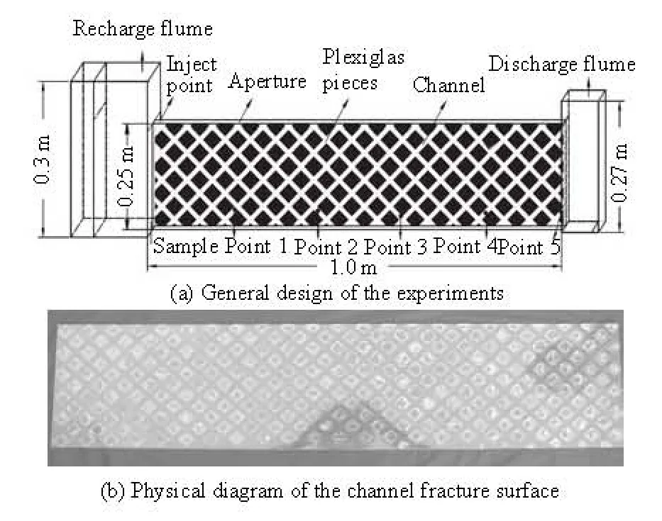
Fig.1 Setup of the experiment
2. Experimental setup and method
2.1 Experimental setup of the single channel fracture
A series of experiments were carried out on an artificial CSF constructed in the laboratory. Though such a model may not represent all features of natural fractures, an excellent control of the flow field can be realized and the influence of specific mechanisms on the groundwater flow can be investigated in great details. Figure 1(a) shows the general design of the setup. The fracture is between two Plexiglas plates of 1 m in length and 0.25 m in height. The hydraulic gradient through the fracture is controlled by adjusting the water level difference between the inflow and the outflow flumes. The fracture is vertical and open at the top, as in an unconfined flow condition. The vertical fracture used here may be different in some respects from horizontal fractures, but the conclusions are not expected to depend on the orientation of the fracture except that there will be a confined flow in a horizontal fracture whereas it will be an unconfined flow in a vertical fracture. Because the hydraulic gradient used in the experiments is small enough over the distance of the flow, the nonlinear effect of the unconfined flow is negligible.
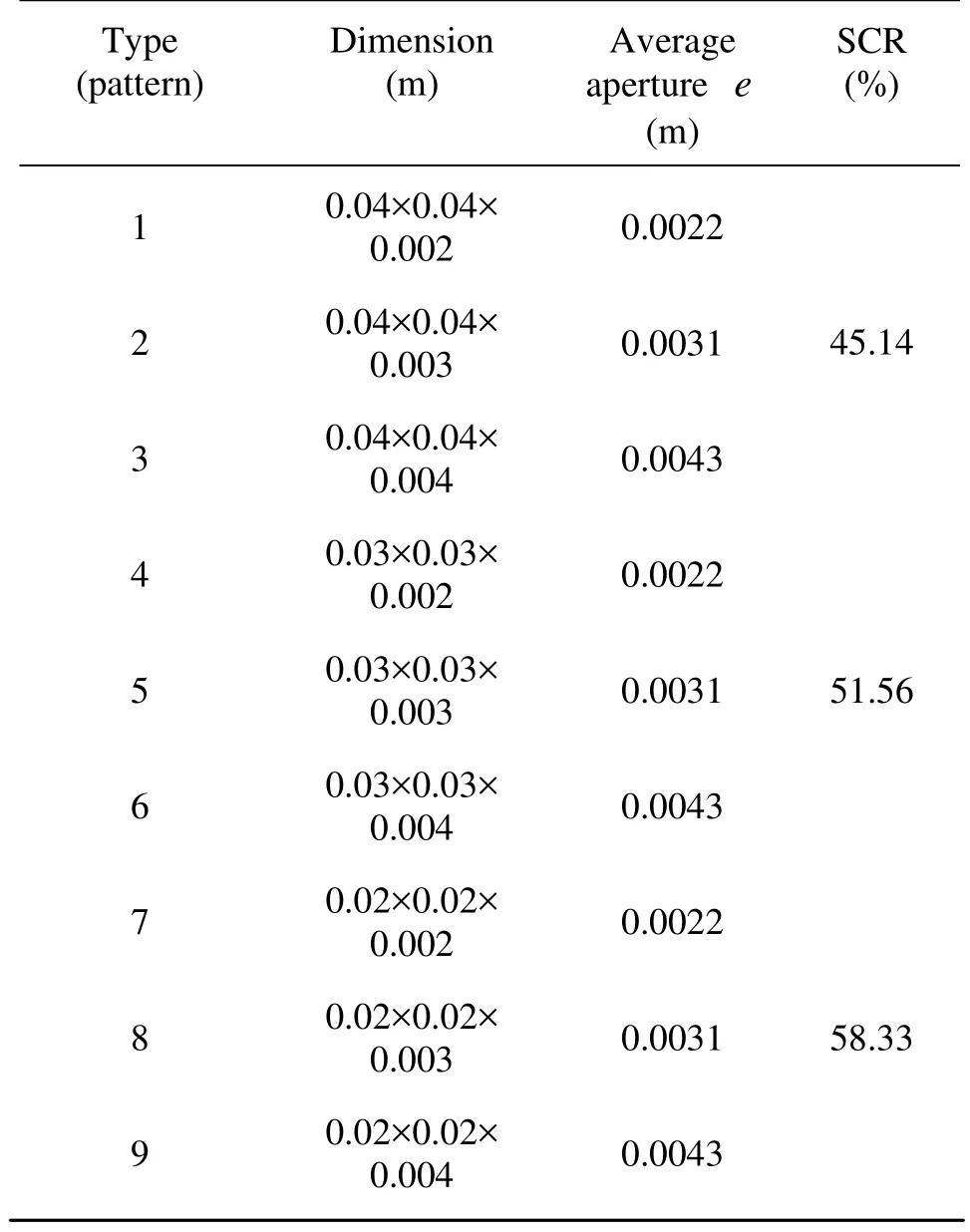
Table 1 Parameters of the experiment apparatus
Figure 1(b) shows the physical design of the channeled rough surface of the CSF, by gluing many square plexiglas pieces to a plexiglas plate by the shape shown in Fig.1(b). Nine different plexiglas pieces are used to represent nine different roughness, namely, Patterns 1 to 9, as is shown in Table 1. We first keep one of the two fracture planes smooth, and the other one to be glued with different Plexiglas pieces selected from Patterns 1 to 9. Then, the two plates are combined and it is ensured that the contact surfaces are plastered together. The channels are formed with different shapes.
A tracer injection device is located at the end of the recharge flume on the left. In addition, five water sample collection devices are located at five points 0.18 m (Point 1), 0.34 m (Point 2), 0.56 m (Point 3), 0.74 m (Point 4) and 0.895 m (Point 5) downstream from the recharge flume on the left, as is shown in Fig.1(a).
2.2 Experimental methods
First, a series of flow experiments were performed on fractures with different patterns (Patterns 1-9) and hydraulic gradients (0.0001-0.0432). To determine the relationship between the average velocity v and the hydraulic gradient J, several water level differences between the recharge and discharge flumes were chosen and the corresponding flow rates were recorded. The associated Reynolds numbers Re were also calculated. Plots of the average velocity versus the hydraulic gradient will reveal whether the Darcy law was valid or not. Steady-state flow rates were monitored using a calibrated flow meter with errors less than 2%, and the water levels were measured with pressure transducers distributed uniformly along the flow path in the fracture, with errors less than 5×10⁻⁴m.
To study the solute transport in a CSF tracer, tests were carried out using a conservative tracer sodium chloride (NaCl). Before the tracer tests, a pilot dye tracer experiment was carried out first to determine the first and last arrival instants, which were used as the references in choosing when the sample collection is taken place in the tracer tests. After the pilot test, the solute of NaCl with a volume of 5 ml and a concentration of 1.0 g/L would be well-mixed and was injected instantaneously by the tracer injection device. After that, water samples each with a volume of 2.5 ml were collected from the sample collection device at Point 1, started 20 s before the first arrival time and ended 40 s after the last arrival time. The experiments will repeat under the same hydraulic condition for the other four sample collection points (Points 2-5). The total volume of the water samples is about 60 ml, small enough not to affect the flow, as compared with the total flux (about 12 L) through the fracture. The values of conductance sμ of the water samples were measured by a conductance instrument DDS-307 (with errors less than 0.1%). Based on the concentration of the injected NaCl and the measured electric conductance, a regressive equation is established

Table 2 Fitting parameters of v- J relationship by Darcy law and Forchheimer equation
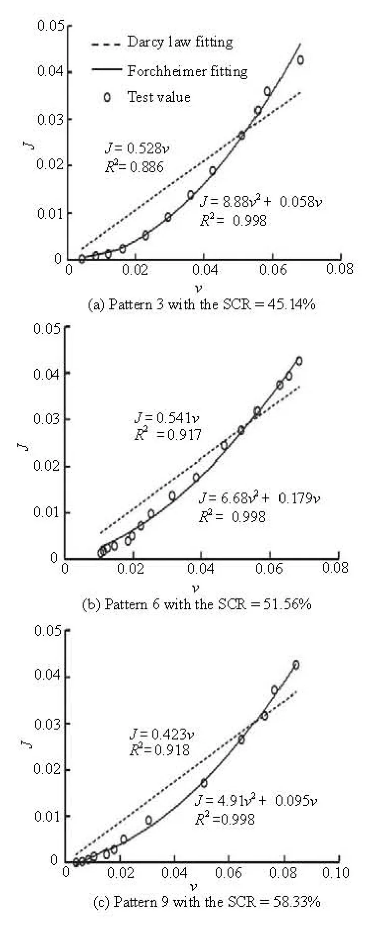
Fig.2 Fitting results of v- J relationship under different fracture patterns

where Ctis the concentration of NaCl solution,sμ is the corresponding electric conductance. The correlation coefficient of Eq.(6) is very close to unity (0.999), indicating a nearly perfect linear relationship between Ctandsμ. Then different BTCs in five different points were obtained and the parameter DLwas determined via the CXFIT 2.1 code.
3. The Analysis of experimental results
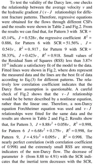
3.1 Flow condition in a CSFwhich may be due to the reduction of the bending degree of the flow path with the SCR and the larger of the SCR, the more similar it is to a porous media.
The minimal and the maximal values of Re are 15.9 and 333.7, respectively. However, one must be careful with the use of the Re as the justification of the Darcy or non-Darcy flow in a CSF because this number is related with a characteristic length which sometimes could be chosen differently. For the flow in a CSF, the characteristic length can be set as the aperture and the average velocity should be the impact of the SCR. The accurate critical Re for the water flow through the CSF cannot be obtained in this paper but the value must be smaller than 333.7.
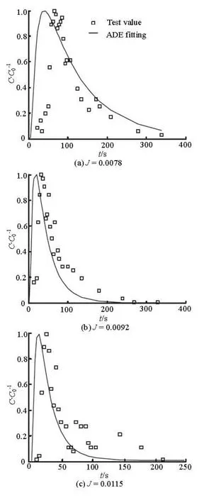
Fig.3 BTCs and fitting curves by ADE under different hydraulic gradients in Pattern 3
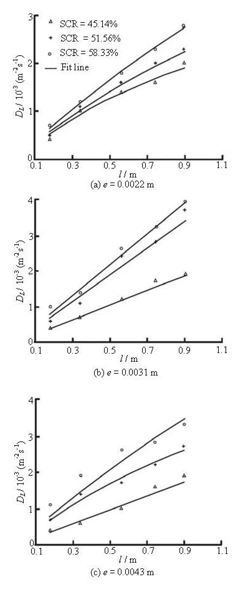
Fig.4 Fitting results of DL-l relationship for different SCRs in different apertures
3.2 Solute transport and scale effect of dispersion coefficient
To describe the solute transport in a CSF under different flow velocities and fracture apertures, several groups of pulse tracer tests were carried out. The BTCs at different collection points were obtained. For instance, samples from collection Point 5 for Pattern 3 under different hydraulic gradients (with J equal 0.0078, 0.0092 and 0.0115) were shown in Fig.3. The results reveal a few important features of the transport. Firstly, all BTCs show asymmetric distributions and long tails, indicating the non-Fickian transport. Secondly, the double-peak or the multi-peak phenomenonof the BTC does appear and the BTC is rough in a high J condition. The multi-peak may be caused by the physical nature of the CSF. The solute may be retained at the corner of the channel when the concentration of the central flux is large and then be released when the concentration is small. Finally, the arrival time of the peak value is shifted to an earlier instant with the hydraulic gradient.
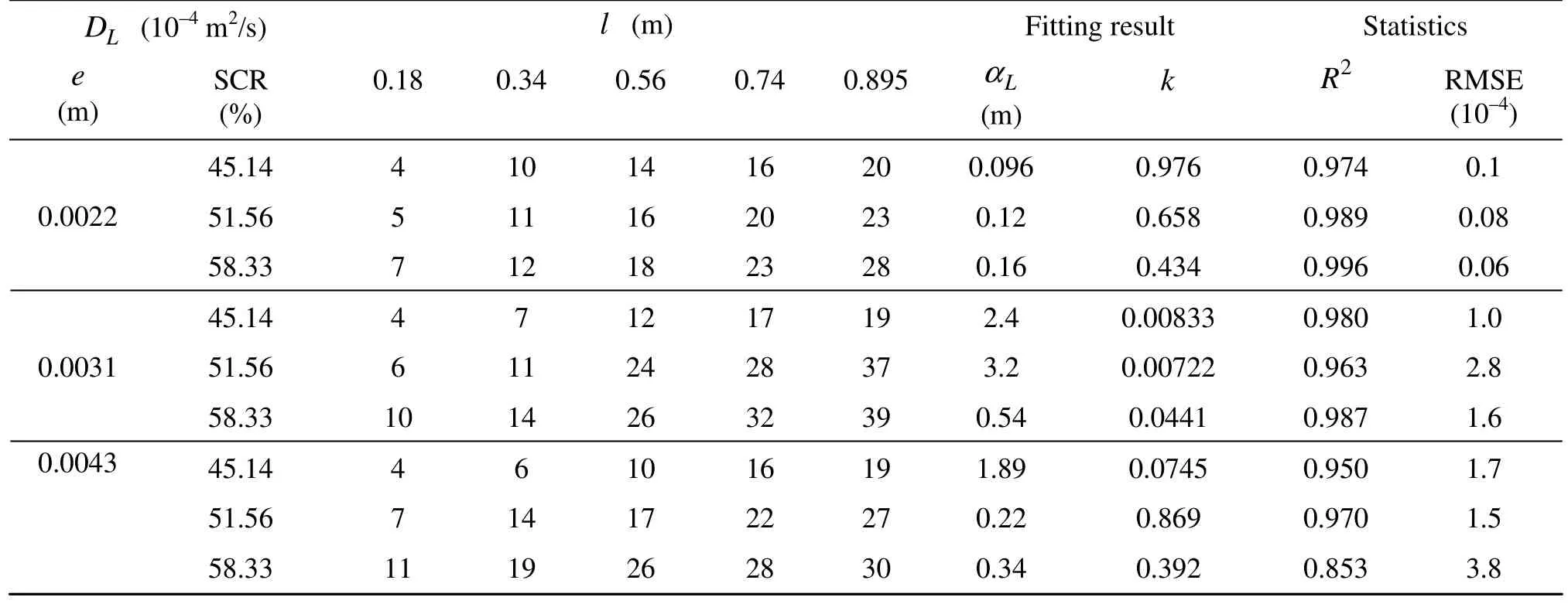
Table 3 Fitting results of the longitudinal dispersion coefficient DLand the travel distance along the flow direction l for three different average apertures by Eq.(5)
The fitting results for Pattern 3 under three different J values of the BTCs and the observed data are shown in Fig.3. The results show that the ADE is not adequate to describe the BTCs in a CSF. It can neither capture the early arrival peak value nor explain the long tailing. The multi-peak phenomenon of the BTC cannot be reproduced by the ADE either. Notwithstanding, the ADE fitting curves still reveal some trends together with the BTCs.
Different values of DLalong the longitudinal are calculated by the CXFIT 2.1 code also and the results are shown in Table 3 and Fig.4. The results show that the value of dispersion coefficient DLincreases with l, as is significantly scale-dependent. The DLvalues increase with the SCR and with the average aperture e. The high regressive coefficient value and the small Root Mean Squares Error (RMSE) show that DL-l relationship can be fitted by an exponential form equation as Eq.(5). The dispersivity values are influenced by the SCR and the average aperture and the exponential coefficient k is less than 1.
4. Conclusions
A physical model of CSF is constructed and the well controlled flow and tracer experiments are carried out. The control parameter of the parallel plate fracture model is the SCR. The average velocity v and Re in a CSF should be defined based on the SCR. The flow condition in a CSF here shows a non-Darcy feature and the BTCs show the non-Fickian phenomena. The v-J relationship can be described well by the nonlinear Forchheimer equation. The parameter b decreases with the SCR, as is caused by the reduction of the bending degree of the flow path with the SCR, which indicates that the inertial term may decrease with the SCR.
Typical non-Fickian phenomena of the early-arrival of the peak value and the long tailing do appear in the BTCs in a CSF. In addition, the double-peak or multi-peak phenomenon of the BTCs appears and the BTC is rough in a high J condition. The multi-peak may be caused by the CSF’s structure. The ADE model is not adequate to describe the BTCs for the CSF. As to the mechanism of the double peak and multi-peak phenomenon, they should be studied in the future.
Longitudinal dispersion coefficient DLis scaledependent in a CSF. The DL-l relationship is of exponential type, as can be described by Eq.(5) well and the DLvalue is influenced by l, e and SCR. Meanwhile, the dispersivity values are influenced by SCR and e and the exponential coefficient k is less than 1.
Acknowledgement
This work was supported by the Creative Research Groups of Hefei University of Technology (Grant No. 2009HGCX0233). Authors thank the reviewers, the editor and Zhan Hong-bin for their constructive comments which helped to improve the manuscript.
References
[1] QIAN J. Z., ZHAN H. B. and CHEN Z. et al. Experimental study of solute transport under non-Darcian flow in single fracture[J]. Journal of Hydrology, 2011, 399(3-4): 246- 254.
[2] TAN Ye-fei, ZHOU Zhi-fang. Simulation of solute transport in a parallel single fracture with LBM/MMP mixed method[J]. Journal of Hydrodynamics, 2008, 20(3): 365-372.
[3] TAN Ye-fei, ZHOU Zhi-fang and HUANG Yong. Solute transport in natural fractures based on digital image technology[J]. Journal of Hydrodynamics, 2009, 21(2): 219-227.
[4] CHEN Zhou, QIAN Jia-zhong and LUO Shao-he et al. Experimental study of friction factor for groundwater flow in a single rough fracture[J]. Journal of Hydrodynamics, 2009, 21(6): 820-825.
[5] BRUSH D. J., THOMSON N. R. Fluid flow in synthetic rough-walled fractures: Navier-Stokes, Stokes, and local cubic law simulations[J]. Water Resource Research, 2003, 39(4): 1085-1099.
[6] ZIMMERMAN R. W., CHEN D. W. and COOK N. G. W. The effect of contact area on the permeability of fractures[J]. Journal of Hydrology, 1992, 139(1-4): 79-96.
[7] QIAN J. Z., CHEN Z. and ZHAN H. B. Solute transport in a filled single fracture under non-Darcian flow[J]. International Journal of Rock Mechanics Mining Sciences, 2011, 48(1): 132-140.
[8] QIAN J. Z., CHEN Z. and ZHAN H. B. Experimental study of the effect of roughness and Reynolds number on fluid flow in rough-walled single fractures: A check of local cubic law[J]. Hydrological Processes, 2011, 25(4): 614-622.
[9] ABELIN H., BIRGERSSON L. and WIDEN H. et al. Channeling experiments in crystalline fractured rocks[J]. Journal of Contaminant Hydrology, 1994, 15(3): 129-158.
[10] BAUGET F., FOURAR M. Non-Fickian dispersion in a single fracture[J]. Journal of Contaminant Hydrology, 2008, 100(3-4): 137-148.
[11] MCKENNA S. A., WALKER D. D. and ARNOLD B. Modeling dispersion in three-dimensional heterogeneous fractured media at Yucca Mountain[J]. Journal of Contaminant Hydrology, 2003, 62-63: 577-594.
[12] ZHAO Z. B., JING L. and NERETNIEKS I. Evaluation of hydrodynamic dispersion parameters in fractured rocks[J]. Journal of Rock Mechanics and Geotechincal Engineering, 2010, 2(3): 243-254.
[13] CARDENAS M. B., SLOTTKE D. T. and KETCHAM R. A. et al. Navier-Stokes flow and transport simulations using real fractures shows heavy tailing due to eddies[J]. Geophysical Research Letters, 2007, 34: L14404.
[14] MORENO L., TSANG C. F. Multiple-peak response to tracer injection tests in single fractures: A numerical study[J]. Water Resource Research, 1991, 27(8): 2143-2150.
[15] WU Rong, ZHOU Zhi-fang. Stochastic single fissure aperture simulation based research of solute transport[J]. Journal of Hohai University (Natural Sciences), 2004, 32(1): 87-90(in Chinese).
10.1016/S1001-6058(10)60172-2
* Project supported by the National Natural Science Foundation of China (Grant No. 40872166)
Biography: CHEN Zhou (1983-), Male, Ph. D. Candidate
QIAN Jia-zhong, E-mail: qjiazhong@gmail.com
杂志排行
水动力学研究与进展 B辑的其它文章
- LATTICE BOLTZMANN METHOD SIMULATIONS FOR MULTIPHASE FLUIDS WITH REDICH-KWONG EQUATION OF STATE*
- DYNAMIC ANALYSIS OF FLUID–STRUCTURE INTERACTION OF ENDOLYMPH AND CUPULA IN THE LATERAL SEMICIRCULAR CANAL OF INNER EAR*
- SIMULATIONS OF FLOW INDUCED CORROSION IN API DRILLPIPE CONNECTOR*
- NUMERICAL SIMULATION OF FLOW OVER TWO SIDE-BY-SIDE CIRCULAR CYLINDERS*
- NUMERICAL STUDY OF HYDRODYNAMICS OF MULTIPLE TANDEM JETS IN CROSS FLOW*
- EXPERIMENTAL STUDY ON SEDIMENT RESUSPENSION IN TAIHU LAKE UNDER DIFFERENT HYDRODYNAMIC DISTURBANCES*
