基于无源性理论的开关磁阻直线电机位置控制
2010-11-04杨金明刘文明赵世伟
杨金明 刘文明 赵世伟 钟 庆
(华南理工大学电力学院广东省绿色能源技术重点实验室 广州 510640)
基于无源性理论的开关磁阻直线电机位置控制
杨金明 刘文明 赵世伟 钟 庆
(华南理工大学电力学院广东省绿色能源技术重点实验室 广州 510640)
基于能量耗散理论和开关磁阻电机原理,提出了一种开关磁阻直线电机(LSRM)的非线性控制器。因电气时间常数远小于机械时间常数,LSRM可视为两时间尺度系统,并可分解为反馈连接的电气和机械两个无源子系统。分别对两个子系统进行无源性控制器设计,因反馈连接的无源子系统仍然保证无源性,从而保证整个系统的全局稳定性,试验结果表明该方法具有优良的性能和鲁棒性,并易于实现。
开关磁阻直线电机 无源性控制 位置控制 两时间尺度
1 引言
现代工业中有很多直线驱动要求,传统的利用旋转式电机加机械转换装置的方法具有一些缺陷,如结构复杂、动态响应时间长、精度受限以及需要经常调校,而直线驱动的电机因无中间转换机构,可避免上述缺陷,直线式驱动受到了越来越多的关注。应用开关磁阻电机原理设计的直线电机具有开关磁阻电机的基本特性,如电机结构简单、适于恶劣环境、可靠性高等优点[1-8]。将旋转磁阻电动机原理应用于直线电动机,其结构设计方面有特殊考虑,文献[1-2]讨论了开关磁阻直线电机的结构设计和特性分析。因开关磁阻电机的磁链与位置和电流呈非线性关系,且具有纹波推力扰动,使其控制复杂,限制了其在高精度场合的应用[9-10]。
针对开关磁阻电机的缺陷,在旋转式电机上已提出一些控制方法[11-18],如反馈线性化控制[14-15]、自校正控制[16]、迭代学习控制[17]、人工神经网络控制[18]等。在开关磁阻直线电机控制上,也有一些有效的方法。如采用力分配函数的方法[4],这种方法简化了励磁绕组的切换控制,但对电机运动控制还需采取措施;基于查表的线性化补偿方法虽然简单[5],但需进行大量的开关磁阻电机特性精确测试,对控制器有较高的要求且鲁棒性差[6-7];文献[8]提出了一种基于无源性理论和路径规划的控制方法,实现了高精度位置控制;文献[19]将自抗扰控制应用于开关磁阻平面电机的控制中,这种方法需调校的参数较多;以上方法强调的是控制器本身的特点,较少考虑开关磁阻电机的结构特性。
本文充分结合LSRM 的能量耗散特性,提出了一种非线性反馈控制方法。基于无源性理论的控制方法已成功应用于旋转式开关磁阻电机及开关磁阻手指夹具的控制中[8,20],但都是将整个传动系统作为控制对象进行控制器设计的,控制器结构较为复杂。考虑到LSRM电气时间常数远小于机械时间常数,可视为一个双时标机电系统,并可分解为反馈连接的电气子系统和机械子系统。分别对两个子系统进行控制器设计,因两个反馈联接的无源子系统的仍然保持无源性[21],整个开关磁阻直线电机传动系统的稳定性得到保证,分解后的系统控制结构简单,易于实现。
2 LSRM结构和模型
2.1 LSRM结构
开关磁阻直线电机的结构和试验样机如图1和图2所示,电动机由动子和定子两部分组成,动子由铝型材制作,惯性小,磁路隔离效果好,三个相同的绕组安装在动子上;定子导轨由条状0.5mm厚的硅钢片叠成,在导轨上的工作行程范围安装了分辨率为0.5µm光码条作为位置检测元件。电动机电气和机械参数见表1。

图1 开关磁阻直线电机结构图Fig. 1 Schematic diagram of the LSRM

图2 LSRM试验样机Fig. 2 The LSRM prototype

表1 开关磁阻直线电机参数Tab.1 The parameters of the LSRM
2.2 LSRM模型
开关磁阻直线电机的动态特性可用电压方程(1)和运动方程(2)表示

式中
uj——绕组j的励磁电压;
ij——绕组j的相电流;
rj——绕组j的电阻;
λj——绕组j的磁链;
x——位置;
fe——电磁推力;
fl——负载;
M——动子质量;
B——摩擦系数。
励磁绕组每相产生的推力

电磁推力为

2.3 LSRM时标分解
将 LSRM 分解为电气子系统Σe和机械子系统Σm,两个子系统连接关系如图3所示。
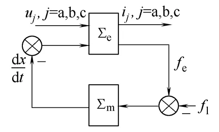
图3 无源子系统分解Fig. 3 Passive subsystem decomposition
Σe和 Σm均为无源映射,即

3 无源性控制器设计
3.1 电气子系统控制器设计
电气回路Σe为一个三阶子系统,定义其状态矢量为:
电气子系统Σe动态特性可表示为

式中 g——输入矢量;
u1——控制信号;
R——结构矩阵,为严格正定对称;
D——电感系数矩阵;
J(z2)——电感变化矩阵,为速度z2的函数。

定义电气子系统Σe的状态误差为:e=z1−zd,其中zd为参考状态矢量,zd决定了要求的Σe特性。将e代入方程(5)得到状态误差方程

对于该误差方程取能量函数

沿状态误差方程(6)对H(e)求时间微分
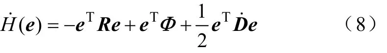

R为严格正定,H˙(e)为严格负定,状态误差子系统严格无源,则Σe是李亚普诺夫稳定的。

式中,K=diag(k1,k2,k3)为正定对称矩阵。

电气子系统仍然稳定,且可通过调节矩阵K的参数来实现性能优化。
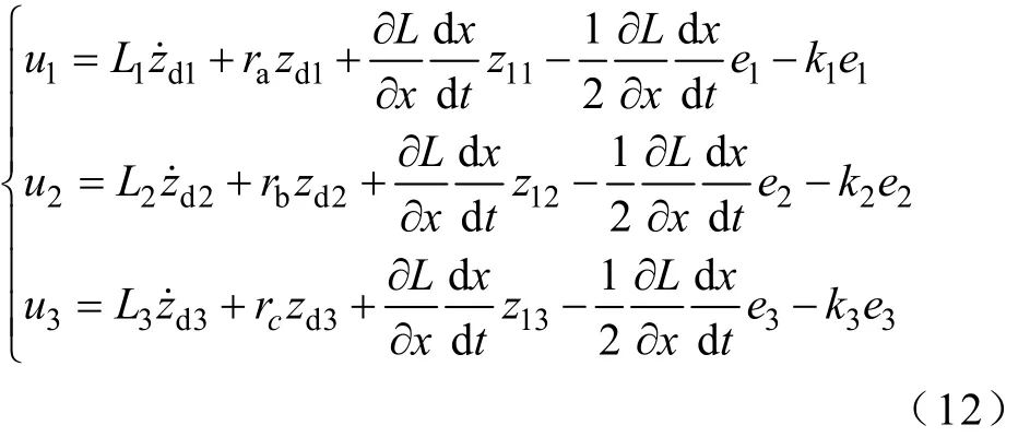
电气子系统Σe的控制律为稳定性仍然可以保证,因电感变化率有界,根据阻尼要求,可以确定矩阵K。
3.2 机械子系统PBC设计
定义Σm的状态变量为z2=v,其动态特性为

其实式(10)只要满足

因Σm的自然阻尼很小,也通过注入阻尼来改善动态特性,控制律为

式中,−k4e4为机械子系统Σm的注入阻尼项。
3.3 LSRM驱动控制
采用双环控制策略的系统结构如图 4,内环为电流环,外环为位置环。

图4 开关磁阻直线电机控制框图Fig. 4 The control diagram of the LSRM system
开关磁阻电机的绕组励磁需与位移同步,本文采取单相和多相绕组励磁相结合的方法,根据运动区域来确定绕组的通电状态,这里采用力分配函数的励磁策略[4],电机位移运动周期为 12mm,将其分为6个区域,根据各个区域和推力指令来分配各个绕组所贡献的推力,以使推力波动小,力分配函数表见表2。
利用力分配函数的励磁策略原理如图5所示。
定义zd2为要求的速度v*,则可根据式(3)和式(4)计算要求的推力

由图4可得每相绕组的参考电流计算如下:

式中,dLj/d x可通过实测和查表的方法得到。
定义整个LSRM驱动系统的能量函数为

对H*(e)沿Σm和Σe动态求时间微分,并代入电气子系统控制律式(12)和机械子系统控制律式(15),很容易证明整个系统的渐近稳定性,且能保证系统的误差指数收敛到零[21]。
4 试验结果
基于dSPACE DS1104 DSP运动控制卡构建的开关磁阻直线电机试验系统结构如图6所示。

图6 试验系统结构Fig. 6 The experimental setup

图7 方波信号输入下的位置跟踪Fig. 7 The experimental curve of position response
图7和图8分别为方波信号输入下的位置跟踪过程和速度变化情况,图9为力指令函数输出的变化情况,由结果可见,力分配函数可根据位置跟踪要求提供合适的指令,且具有满意的动态过程。图10为跟踪正弦信号的过程。
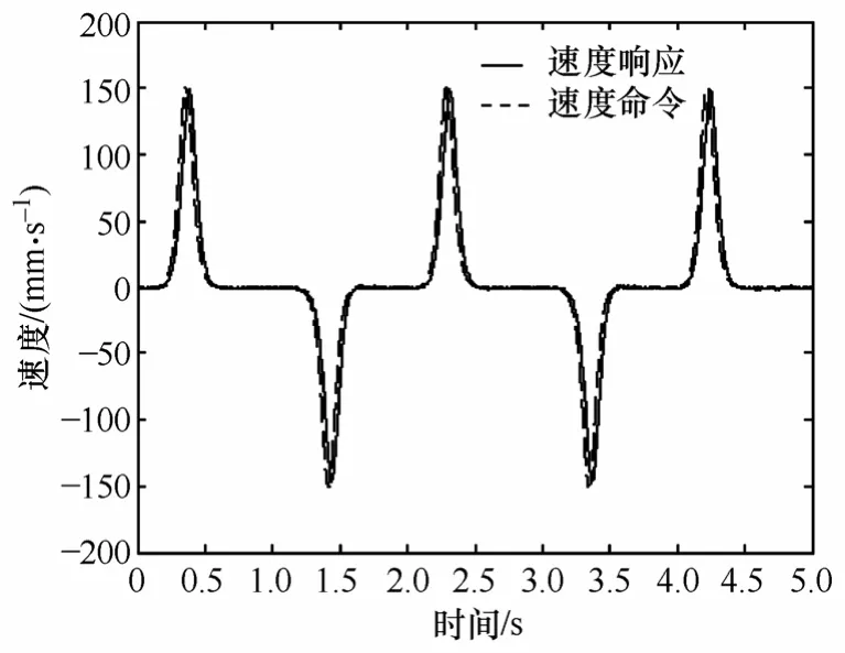
图8 方波信号输入下的速度变化Fig. 8 The experimental curve of speed response

图9 力指令信号Fig. 9 Command signal of force
为了验证本文提出方法的有效性,进行了与PID控制及负载变化情况下的对比试验,图11为正常条件下的对比试验,图12为动子质量增加150%时的对比试验,结果表明本文提出的PBC方法具有更好的动态过程和抗扰动鲁棒性。

图10 正弦信号跟踪过程Fig. 10 Position response of sinusoidal wave
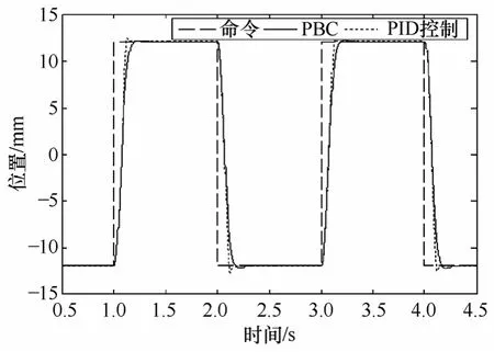
图11 正常情况下的PBC与PID控制对比Fig. 11 The position tracking waveforms

图12 动子质量增加50%时的PBC与PID控制对比Fig. 12 The position tracking with the 150% mass increase
5 结论
将LSRM驱动系统分解为电气子系统和机械子系统,并分别对两个子系统进行无源性控制器设计,系统分解降阶,降低了控制器的复杂性,使控制系统易于实现,并通过注入阻尼改善系统动态特性,试验结果表明本文提出的方法较PID控制具有更好的动态特性和抗干扰性,适用于时间常数相差大的复杂高阶系统的控制。由于采用了磁导率低的铝型材,存在效率较低的缺陷。其他磁导率高的材料,进而实现实用化,是下一步要进行的工作。
[1] Deshpande U S, Cathey J J, Richter E. High-force density linear switched reluctance machine[J]. IEEE Trans. Ind. Applicat., 1995, 31(3): 345-352.
[2] Lee B S, Bae H K, Vijayraghavan P, et al. Design of a linear switched reluctance machines[J]. IEEE Trans. Ind. Applicat., 2000, 36(11): 1571-1580.
[3] Gan W C, Cheung N C, Qiu L. Design of a linear switched reluctance motor for high precision applications[C]. Electric Machines and Drives Conference, 2001: 701-704.
[4] Bae H K, Lee B S, Vijayraghavan P, et al. A linear switched reluctance motor: converter and control[J]. IEEE Trans. Ind. Applicat., 2000, 36(9): 1351-1359.
[5] Gan W C, Cheung N C, Qiu L. Position control of linear switched reluctance motors for high precision applications[J]. IEEE Trans. Ind. Applicat., 2003, 39(9): 1350-1362.
[6] Gan W C, Chan K K, Widdowson G P ,et al. Application of linear switched reluctance motors to precision position control[J]. Power Electronics Systems and Applications, 2004 Proceedings, 11: 254-259.
[7] Gan W C, Cheung N C, Qiu L. Short distance position control for linear switched reluctance motors: plug-in robust compensator approach[C]. Industry Applications Conference, 2001: 2329-2336.
[8] Yang J M, Jin X, Wu J, et al. Passivity-based control incorporating trajectory planning for a variablereluctance finger gripper[J]. Proc. Instn Mech. Engrs Part I: J. Systems and Control Engineering, 218, 99- 109.
[9] Miller T J E. Switched reluctance motor and their control[M]. London, :Oxford Univ. Press, 1993.
[10] Khorrami F, Krishnamurthy P, Melkote H. Modeling and Adaptive nonlinear control of electric motors[M]. Germany: Springer, 2003.
[11] Borka J, Lupan K, Szamel L. Control aspects of switched reluctance motor drives[C]. Industrial Electronics Conference Proceedings, 1993, 6: 296-300.
[12] Goldenberg A A, Laniado I, Kuzan P, et al. Control of switched reluctance motor torque for force control applications[J]. IEEE Trans. Ind. Electron., 1994, 41(8): 461-466.
[13] Ma B Y, Liu T H, Feng W S. Modeling and torque pulsation reduction for a switched reluctance motor drive system[C]. Proceedings of the 1996 IEEE IECON 22nd International Conference on Industrial Electronics, Control, and Instrumentation, 1996, 1: 72-77.
[14] Panda S K, Dash P K. Application of nonlinear control to switched reluctance motors: a feedback linearization approach[J]. IEE Pro-Electr. Power Appl, 1996, 3: 371-379.
[15] Ilic’Spong M, Marino R, Peresada S M, et al. Linearizing control of switched reluctance motors[J]. IEEE Trans. Automat. Contr, 1987, AC-32: 371-379.
[16] Milman R. Bortoff S A. Observer-based adaptive control of a variable reluctance motor: experimental results[J]. IEEE Trans. Contr. System Tech., 1999, 7(7): 613-621.
[17] Sahoo S K, Panda S K, Xu J. Indirect torque control of switched reluctance motors using iterative learning control[J]. IEEE Trans. on Power Electronics, 2005, 20(1): 200-208.
[18] Xia C, Chen Z, Xue M. Adaptive PWM speed control for switched reluctance motors based on RBF neural network[C]. Proceedings of the 6th World Congress on Intelligent Control and Automation, June 21-23, Dalian, China, 2006: 21-23.
[19] Pan J F, Cheung N C, Yang J M. Auto-disturbance rejection controller for novel planar switched reluctance motor[J]. IEE Pro-Electr. Power Appl, 2006, 153(2): 307-316.
[20] Espinosa Pérez, Maya Ortiz G P, Velasco M Vill, et al. Passivity-based control of switched reluctance motors with nonlinear magnetic circuits[J]. IEEE Trans. Contr. System Tech, 2004, 12(3): 439-448.
[21] Ortega, Romeo. Passivity properties for stabilization of cascaded nonlinear systems[J]. Automatica, 1991, 27(2): 423-424.
Position Control of Linear Switched Reluctance Motor Using Passivity-Based Control
Yang Jinming Liu Wenming Zhao Shiwei Zhong Qing(Guangdong Key Laboratory of Clean Energy Technology
South China University of Technology Guangzhou 510640 China)
By using the energy dissipation theory and the property of the switched reluctance motor, this paper presents a nonlinear controller for the linear switched reluctance motors (LSRM). Based on the fact that the electrical time constant is much smaller than the mechanical time constant, the whole LSRM driving system is treated as a two-time-scale system and can be decomposed into two subsystems (electrical and mechanical) that are negative feedback interconnection. The controllers are designed for two subsystems respectively to ensure that they are passive. In view of the fact that the system made of two passive subsystem connected through negative feedback is still passive. Therefore, the stability of LSRM driving system is ensured in large scale. This control strategy possesses a simple structure and can be implemented easily. The experimental results show that the proposed control is effective and roboust for the position control of LSRM.
Linear switched reluctance motor (LSRM), passivity-based control(PBC), position control, two-time-scale
TM351
杨金明 男,1962年生,博士,教授,主要研究方向为电气传动、风力发电和光伏发电技术、控制理论与控制工程。
国家自然科学基金(60674099)和国家自然科学基金重点(60534040)资助项目。
2008-12-13 改稿日期 2009-08-20
刘文明 男,1988年生,硕士研究生,主要从事电力电子技术及其控制技术研究。