微型叶轮机械联合试验台设计
2010-05-05黄国平
夏 晨 黄国平 陈 杰
(南京航空航天大学能源与动力学院,南京,210016,中国)
INTRODUCTION
Micro-turbine engine(M TE)is a novel power with the small size,the light weight,the high thrust-weight ratio,and the high energy density.It can be used in the micro aircraft asthe propulsion system and in the distributed generation or auxiliary power unit as the core module.Many researchers have paid attention to MTE and have done many investigations because of the good application of M TE.Ref.[1]studied a 30 N-model jet engine on a test bench,and a new aero-engine with 100 N thrust was designed and tested on the test bench.A small single-shaft turbojet engine with the ceramic nozzle and the turbine rotor was tested by AIST and the turbine inlet temperature reached 1 550 K[2-3].There is not enough space in M TE for accurately measuring the impeller performance because of the small size and the compact structure,so most researches are carried out for testing the whole micro-engine.Only Refs.[4-7]measured the micro-turbo-machinery performances.In order to predict the engine operating status ateach rotation speed and promote the engine performance,the turbo-machinery performance of MT E must be accurately measured.
NASA Lewis Research Center carried out many turbo-machinery tests,and some test benches for the small centrifugal and the radial inflow turbine were built. The centrifugal compressor diameters in the test are from 4.25 inch to 6.44 inch(107.95 mm to 163.6 mm)[8-10],and the radial inflow turbine diameters in the test are from 3.5 inch to 6.02inch(88.9 mm to 152.9 mm)[11-13].The effects of Reynolds number,inducer inlet areas,specific speed,and diffuser throat area were researched[13-16]. But all experiments are used for the centrifugal compressor or the radial inflow turbine separately.Besides,turbine tests in Ref.[12]were cold performances and under the normal working temperature. So,the full turbine characteristics are not represented.
A new micro-turbo-machinery test facility is designed for the centrifugal compressor and the radial inflow turbine ofM TE with 12 cm diameter.The facility can be used for the full speed compressor test and the long duration hot turbine test.The centrifugal compressor diameter is 84 mm and the diameter radial inflow turbine is 78 mm.The flow rate of engine at designing point is 0.4 kg/s and the maximum rotation speed is 125 000 r/min.
1 TEST FACILITY CONSTRUCTION
1.1 Fundamental structure
In order to obtain the impeller characteristics accurately and conveniently,the facility must have capabilities as follows:(1)The compressor characteristics with full size at full speed and the turbine hot performance with long duration can be tested,respectively.(2)The size universality for a series of impellers and the functional extendibility for parameter measurement and data acquisition are required.(3)The work condition can be automatically adjusted by the control system.
The test facility includes the air compressor,the surge tank,the heater element,the electric control valve,the electric check valve,the torque measuring system,the test portion,the control system,the measuring system,and the safety system. Fig.1 shows the principle of the test facility. The aircompressorcan supply the compressed airto the heaterelement. The maximum flow rate is 1.2 kg/s and the highest pressure is 6 bars.The core of the heater element is a micro-annual combustor with evaporators.The heater element can heat the compressed air to 1 200 K. The electric control valves with an adjustable accuracy of 0.1% are used for regulating the air flow rate of the testing turbomachineries.The response time of the electric check valve is less than 1 s,and it works when the compressor is surging.

Fig.1 Micro-turbo-machinery test facility

Fig.2 Configuration of test portion
The test portion includes the compressor and the turbine assembles,as shown in Fig.2.And it can obtain the impeller characteristics of the centrifugal compressors and the radial inflow turbines,respectively. The torque measuring system can obtain the accurate impeller efficiency with the rotation speed.The control system can adjust the power matching between the compressor and the turbine with separated flow paths by regulating the electric valves and the fuel delivery of the oil pump.Aerodynamic parameters of the main sections such as pressure,temperature and rotating speed are measured by the measuring system.The safety system includes the test-bed vibration signal monitor system and the anticompressor-surge system. The vibration signal monitor system monitors the vibrations of the bench and shuts down the fuel supply when the vibration exceeds the safety limit. The anticompressor-surge system can quickly eliminate the compressor surge.
Compared with the normal turbo machinery test beds with only one air path[17-19],the facility has two air paths.One air steam is sucked by the air compressor and transported into the heater element. The compressed air is heated to the required temperature and drives the radial inflow turbine offering power to the centrifugal compressor,and then the hot compressed gas is exhausted to atmosphere.Another air steam is compressed by the centrifugal compressor and ejected to atmosphere through the compressor assembles.The two paths are remarked as white and black arrows in Fig.1.The combustor is not located between the compressor and the turbine.The space is used forinstalling the torque transducer to measure the shaft torque.So the bench can measure the characteristics ofthe centrifugal compressors and the radial inflow turbines,respectively.The turbine drives the compressor as the powersupplier during the compressor tests,and the compressor regulates the turbine operating states as the load in the turbine tests.The maximum rotating speed is 125 000 r/min,and the flow rate differs from 0.1 kg/s to 1.0 kg/s. The maximum inlet total temperature of the turbine nozzle is 1 180 K.
1.2 Removable configuration
In order to conveniently fix or remove the test portion and enhance the utilization rate of the bench,the test portion is modularly designed.The components of the test portion include the essential components,the testing components and the removable components,which are grouped by replace ability,as shown in Fig.3.The testing components include the shaft,the compressor rotor,the diffuser,the turbine rotor,the turbine nozzle,and the casings of the impellers.The essentialcomponents include the intake and exhaust ducting,the pedestal,the brackets,and the sealed parts.These components form the main body of the test portion and cannot be changed for the various tests. The removable components include the connect pipes and the bearing holders for different impellers with a series of size.If the size of testing impellers is not changed but the blade shape and the meridian path are changed,the test can be carried out by alerting the testing parts.If the size of testing impellers is changed,the test can be carried out by alerting the testing parts and the connect pipes. The test-bed is designed to testthe compressor parts with the diameters from 60 mm to 180 mm and the turbine partswith the diameters from 55 mm to 180 mm because of its modular configuration.
The test facility can be used for testing the centrifugal compressorand the radial inflow turbine characteristics with a series ofsize respectively as a result of the novel construction.It is convenient for testing and enhancing the utilization rate of the bench.
1.3 Lubricant circuit and thermal protection
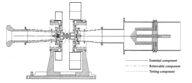
Fig.3 Cross section of test portion
As the turbine is driven by the hot compressed gas,the turbine assembles must endure the high temperature. The highest temperature is 1 200 K at the exit of heater element,so the turbine assembles transfer heat to the outside when the hot gas passing through them. The thermal deformation of each component caused by the heat transfer is different,which leads to the de-concentricity of the rotating assembly.The rotor can crash the casing if the de-concentricity is serious.The heat also radiates to the environment and causes the temperature raise.The temperature upper limit of electric elements in the torque transducer is 50°C,so it effects the normal operation of the electric elements and results in an unsuitable working condition.The rotors are held by the ceramics ball-bearings.The rotating speed that can damage the bearings is 125 000 r/min and the temperature upper limit is 300°C.The hot gas leakage from the turbine rotor disk invalidates the bearing.So the bearing must be lubricated and the hot gas must be sealed,and the lubricate circuit and the thermal protection system are designed for the test portion.

Fig.4 Lubricant circuit,seal and cooling methods for turbine assembles
Fig.4 shows the lubricant circuit,the seal and the cooling methods for turbine assembles.A seal is fixed at the back of the turbine disk to prevent the hot gas from leaking into the bearing.The cooling compressed air passes through 4 holes of the bearing holder and 36 holes of the seal to the cavity back of the turbine disk,and cools the bearing holder to reduce the thermal deformations and stops the hot gas leakage.It can also keep high pressure in the cavity between the turbine disk and the bearing holder.The lubricant oil passes through the holes of the bearing holder to the bearing.It is driven by the cooling compressed air passing through the bearing to the grating disk and thrown out to the outer edge of the oil remover by the centrifugal pull.The oil accumulates at the bottom of the oil remover and is sucked by an oil pump.The radial gap between the grating disk and the oil remover is 0.5 mm in which lubricant oil can be leaked because of the high pressure in the cavity,so the sealed compressed air passes by the three holes of the oil remover to seal the oil and keep the differential pressure at both sides of the bearing.The paths of lubricant oil,cooling and sealed compressed air are marked by different arrows,respectively in Fig.4.The lubricate circuit and the sealed method of the compressor are the same as those of the turbine.In order to reduce the heat dissipating capacity from high temperature parts,such as the turbine volute,a thermal barrier coating is put on the surface of the hot components,as shown in Fig.5.It provides a proper working environment for the electronic components in control and measuring systems.

Fig.5 Thermal protection of hot components
The lubricant circuit and the thermal protection resolve the thermal deformations and the heat transfer caused by the high temperature which does not exist during the normal cold testing.
2 TESTING AND CONTROLLING
2.1 Testing process
The test facility can be used for the impeller characteristic test of the centrifugal compressor and the radial inflow turbine,respectively.The compressor testing process as follows:(1)The numerical simulations are carried out by the numerical computational software NAPA for the compressor and the turbine with different rotation speeds and flow rates,and the simulation results are used for defining the cooperation points by using the commercial gas turbine performance analysisprogram GASTURB. Foraccurately computing the cooperation points, at least5 rotation speed conditions are simulated,and each speed includes 7 flow conditions.(2)Under the specific compressor working condition,the exit static pressure of compressor, the inlettotal pressure,the inlet total temperature,and the exit static pressure of turbine are determined according to the numerical simulation results.Aftersetting the electric control valves,the throttle cone and the oil pump approaching the working station,the air compressor is started and the compressed air from the air compressor is burned in the heater element.The oil flow rate is regulated according to the exit temperature of the heater element and provides the suitable temperature rise.The turbine driven by the hot compressed gas offers the power to the compressor and the turbine output is adjusted by regulating the electric control valves, the oil pump and the throttle cone.The rotation speed is shown on the computer screen simultaneously to estimate the operating states.When the speed R is greater than the target value R0,the turbine output is reduced by turning dow n the electric control valve2or reducing theoil supply to decrease theturbine rotating speed.When R<R0,the turbine output is raised by turning up the electric control valve2or adding the oil supply to increase the turbine rotating speed.The compressor characteristics with a series of rotating speeds and flow rates are measured by adjusting the turbine output.In turbine engines,the turbine inlet temperature is very high when the operatingpoint approaches the surge margin. But the test facility supplies the individual path for the compressor and the turbine,respectively,so the turbine inlet temperature can be reduced by increasing the turbine air supply.It is more safe.The compressor testing process is shown in Fig.6.
The turbine testing process is the same as the compressor testing process. The centrifugal compressor isthe load ofthe radial inflow turbine.The electric control valve,the oil pump and the throttle cone are regulated to adjust the turbine operating states. The turbine characteristics with a series of rotating speeds are
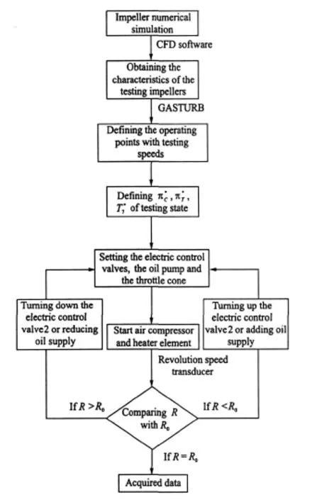
Fig.6 Testing process of compressor experiments obtained by regulating the compressor working conditions.
2.2 Control system
During the testing process,the working conditions of the compressor and the turbine must be synchronously adjusted,and the demand for the regulation accuracy is strict.For the rapid and effective testing,the control system of the facility is designed for regulating operating states automatically. The equipments need to be regulated during the test process,including the electric controlvalve 1 downstream ofthe compressor assembles exit,the electric control valve 2 upstream of the heater element inlet,the electric check valve downstream of the compressor assembles exit and the oil pump.The functions of the control system are as follows:(1)The electric valves and the oil pump are regulated. The powermatching between the compressor and the turbine can be automatically adjusted.(2)The rotating speed signal and the bench vibration signal are monitored and exported to the computer screen synchronously during the testing process.(3)The switch signal of the decompression protection for the oil pump is set.When the speed exceeds the upper limit,the pressure for pumping oil is quickly reduced to prevent over speed.(4)The switch signal of the electric check valve for opening rapidly is set.When the compressor surge appears,the electric check valve opens quickly to eliminate it.
2.3 Safety system
The safety system of the facility is designed to ensure the normal operation.It includes the test facility,vibration signal monitor system and the anti-compressor-surge system.
The vibration transducers are fixed on the pedestal to monitor the vibration of the facility caused by the high-speed rotation.The vibration monitor results are shown on the computer screen to estimate the safety of the rig simultaneously.When the vibration exceeds the upper limit,the control system shuts dow n the fuel supply of the heater element to reduce the rotating speed.For reducing rotorsystem vibration, the inertia balance is completed by the dynamic balance machine before testing.The test facility vibration signal monitor system can prevent the rig from breakdown by the strong vibration.
There are an electric control valve and an electric check valve on the downstream of the compressor volute.Usually,the electric check valve is closed until the compressor surging.At the compressor volute exit,the static pressure is monitored by the pressure transducer.When the static pressure sharply decreases, which is counted as the compressor surge,the electric check valve is quickly opened by the control system to reduce the static pressure and increase the flow rate of compressor. The anticompressor-surge system can quickly eliminate the compressor surge and safely ensure the rig.
The temperature at the heater element exit is monitored by the thermocouple too.When the temperature exceeds the upperlimitofthe material,the oil supply is shut down.
3 DATA ACQUISITION
3.1 Torque measurement

Fig.7 Torque measuring system
The output power of the turbine is important for obtaining the accurate efficiencies of compressor and turbine. The shaft torque measurement is the main difficulty in the output power measurement.The conventional airbrake dynamometer cannot be used because of the test facility structure. There is nota flexibility coupling which can suffer a high speed of 125 000 r/min.So,a photoelectric torque transducer is designed to measure the shaft torque accurately.Fig.7(a)shows the principle of the torque transducer.Two grating disks are fixed on the shaft.The grooves of the two grating disks are staggered.The luminary and the photo sensor are outboard at both sides of the grating disks.When there is no torque transferred by the shaft,the light cannot pass through two grating grooves simultaneously and the photo sensorcannot receive the light signal and has no export.When the shaft is twisted by the torque,there is a relative twist angle between two ends of shaft.The light can pass through the two grating grooves simultaneously.And be received by the photo sensor.The export signal intensity of the photo sensor is depended on the relative twist angle which is in proportion to the torque.When the torque increases,the relative angle between two grating disks rises and the slit in which the light passes through becomes larger. The luminous flux and the light intensity increase,and the electric current ofthe photo sensor increases too.So the electric current of the photo sensor can be used for representing torque strength.
Thistorque transducerisbased on the photoelectric effect, and the electromagnetic interference influence is smaller. Its response time is less than 1 ns. But there are many difficulties fordesigning: (1) Because the rotating speed reaches 125 000 r/min,the photo sensor must have a high response speed. The response time is 480μ s/r,and the pulse width of light intensity is about 3μ s.It requires the high sampling rate of the analog digital conversion.(2)The manufacturing accuracy of grating disks is demanded, and the configuration and the strength of grating disks are required because of the high speed revolution.(3)The maximum torque is 7.7 N·m and the maximum twist angle hmaxis 0.131°,so the high measuring accuracy is demanded.
The photoelectric torque transducer is designed and manufactured.The calibration test of the transducer is show n in Fig.7(b).It can suffer the high speed of 125 000 r/min,and the measuring accuracy is 1%.
3.2 Other measurements
The rotating speed,the flow rate, the pressure,and the temperature of main sections are measured during the test process by measuring system of the facility for obtaining the accurate impeller characteristics.
A couple of small magnetic beads is fixed on the back ofthe centrifugalcompressordisc symmetrically. It can be used formeasuring revolution speed based on the galvanomagnetic effect.The flow rate is measured by the V-cone pressure-difference mass-flow meters with an accuracy of±0.5%,and the fixing stations are show in Fig.1.
The pressure and the temperature of main sections are measured by the pressure probes,the static tapsand the armored thermocouples.Fig.8(a)shows the measurement stations of the impeller testing,in particular for the Stations 1,2,7 and 9.The remark numbers of the sections are the same as the Fig.1.When placing the probes and the thermocouples,the symmetry pressure and the temperature distributions are assumed.
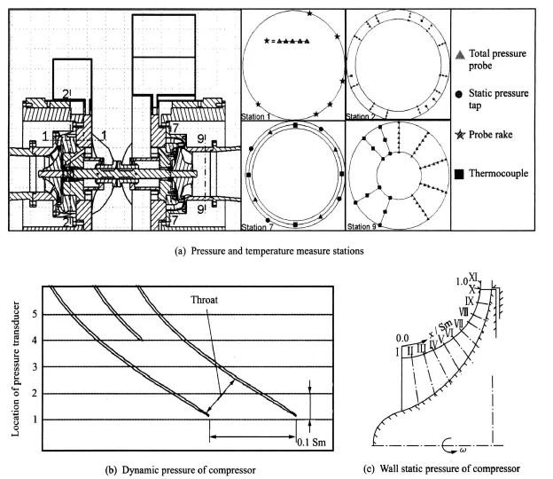
Fig.8 Measuring stations
The centrifugal compressor has 10 blades and 10 splitterblades. Atthe compressor exit,station 1,the total pressure is measured on the downstream of the rotor trailing edge(105% of the exit diameter)with 6 probe rakes for a pitch.Every rake spaces 6°circumferentially relative to the same vane cascade with 5 probes,as shown in Fig.8(a)Station 1.
The diffuser has 15 blades and 15 splitter blades. At the diffuser exit,Station 2,about 2 mm (10% of the diffuser axialchord)downstream of the blade trailing edge,both total temperature and total pressure are measured by 12 probe rakes and 4 thermocouples.Because of the small cascade height,the two probe rakes form a team to measure the total pressure of the same circumferentially position, and the two rakes probes are staggered in the radial direction.Every team spaces (4°) iscircumferentially relative to the same vane cascade. Four thermocouple spaces(6°)are circumferential for a pitch at the same station as probe rakes.There is not enough space for the probe rakes and the thermocouples simultaneously downstream of the compressor, so the thermocouples for total temperature measurement at the rotor exit are fixed as the same as the diffuser,as show n in Fig.8(a)Station 2.
At the turbine nozzle inlet,Station 7,about 8 mm(50% of nozzle axial chord)upstream of the blade leading edge,the static pressure,the total pressure and the total temperature are measured.Four static pressure taps,four total pressure probes and fourthermocouplesare equally spaced at the circumference of the nozzle inlet,as shown in Fig.8(a)Station 7.
The radial inflow turbine has 12 blades.At the turbine exit,Station 9,the total pressure and the totaltemperature are measured on the downstream of the rotor trailing edge(25% of the axial chord) with 5 probe rakes and 4 thermocouple rakes for a pitch,as shown in Fig.8(a)Station 9.Every probe rake space(6°)is circumferentially relative to the same vane cascade with 7 probes,and every thermocouple rake space (7.5°) is circumferentialwith 3 thermocouples.
The test compressor is a micro-high-speed transonic centrifugal impeller,so the structure of the flow field is complex.In order to obtain more flow information in the rotor, the dynamic pressure in the compressor and the static pressure of wall on-way are measured. The dynamic pressure is measured by 5 dynamic pressure transducers whose diameter is 1.6 mm. The measurement accuracy of the transducer is±0.1%,and the sampling frequency is 250 kHz.The transducers can acquire more than 10 pressure signals for a compressor channel per revolution.The fixed positions are shown in Fig.8(b).11 static taps are located on the compressor casing wall to measure the static pressure onway,as shown in Fig.8(c).As there are not suitable micro-dynamic pressure transducers for high temperature,the dynamic pressure is not measured in radial inflow turbine.There are only 9 static taps on the turbine casing wall to measure the static pressure on-way,and the measurement station isthe same ascompressor. Allthe measuring parameters are summarized in Table 1.
The measuring parameters are acquired by the data acquisition card.The sampling rate of static parameters is 4—100 Hz,and the sampling rate of dynamic parameters is 250 kHz. All measurement data are storage in a computer.The rotation speed and the vibration signal are shown on the computer screen instantaneously to monitor the working stations. The static pressure, the total pressure, the total temperature,the rotation speed,and the shaft torque are simultaneously storaged.Experimental data are useful for impeller characteristic analysis.

Table1 Measuring parameters
4 CONCLUSIONS
This paper designs a new test facility for micro-turbo-machinery. The construction,the controlsystem, the safety system,and the parametermeasurementare introduced. The conclusions can be drawn as follows:
(1)The design concept and the construction of the micro-turbo-machinery test facility are used for the full speed compressor test and the long duration hot turbine test.
(2)The test facility is used for testing impeller characteristics with a series of diameters from 55 mm to180 mm by changing the removable parts asa resultofthe modular design.
(3)The control system is used to adjust the power matching between the compressor and the turbine,and to change the working conditions of the impellers.
(4)A photoelectric torque transducer with an accuracy of 1% is used to measure the torque of a rigid shaft at a high speed of 125 000 r/min.
(5)A thermal protection system is used to avoid the heat distortion caused by the high temperature of turbine assembles and provide the proper operating environment for electronic components.
[1] Gerendas M,Pfister R.Development of a very small aero-engine[C]//Proceedings of ASM E Turbo Expo 2000.M unich,Germany:ASM E,2000:GT2000-0536.
[2] Yoshida H,Matsunuma T,Norihiko I,et al.Micro gas turbine with ceramic rotor[C]//Proceedings of ASM E Turbo Expo2004.Vienna,Austria:ASM E,2004:GT2004-53493.
[3] Matsunuma T,Yoshida H,Norihiko I,et al.Micro gas turbine with ceramic nozzle and rotor[C]//Proceedings ofASME TurboExpo2005.Reno-Tahoe,Nevada,USA:ASME,2005:GT2005-68711.
[4] Wei H,Chiang D,Hsu C N.An investigation of steady and dynamic performance of a small turbojet engine [C]//Proceedings of ASM E Turbo Expo 2002.Amsterdam,the Netherlands:ASME,2002:GT2002-30577.
[5] WeiH,ChiangD,Hsu C N,et al.Dynamic performance of a small turbojet engine [J].International Journal of Turbo and Engines,2003,20:195-207.
[6] Peirs J,Reynaerts D,Verplaetsen F.Development of a micro gas turbine for electric power generation[C]//The 14th Micro M echanics Europe Workshop.Delft,the Netherlands:MM E,2003:215-219.
[7] Wen Quan.Aerodynamic design and performance test for radial inflow turbines of micro turbines[D].Nanjing: Nanjing UniversityofAeronautics and Astronautics,2004.(in Chinese)
[8] Weigel C,Tysl E R,Ball C L.Overall performance in argon of 4.25-inch sweptback-bladed centrifugal compressor[R].NASA TM X-2129,1970.
[9] Tysl E R,Ball C L,Weigel C,et al.Overall performance in argon ofa 6-inch radial-bladed centrifugal compressor[R].N ASA TM X-1622,1968.
[10]Weigel C,Ball C L,Tysl E R.Overall performance in argon of a 16.4-centimeter (6.44-inch)sweptback-bladed centrifugal compressor [R].NASA TM X-2269,1971.
[11]KofskeyM G,WasserbauerC A.Experimental evaluation of a3.50-inch radial turbine designed for a 10-kilowatt space power system[R].N ASA TN D-5550,1969.
[12]Wasserbauer C A,Kofskey M G.Cold experimental evaluation of a4.59-inch radial turbine designed for a brayton-cycle space power system[R].N ASA TN D-3260,1966.
[13]Holeski D E,Futral S M.Experimental performance evaluation of a 6.02-inch radial-inflow turbine over a range of Reynolds number[R].N ASA TN D-3824,1967.
[14]Heidelberg L J,Ball C L,Weigel C. Effect of Reynolds number on overall performance of a 6-inch radial bladed centrifugal compressor[R].N ASA TN D-5761,1970.
[15]Klassen H A.Effect of inducer inlet and diffuser throat areas on performance of a low pressure ratio sweptback centrifugal compressor[R].NASA TM X-3148,1975.
[16]KofskeyM G,WasserbauerC A.Experimental performance evaluation of aradial-inflow turbine over a range of specific speeds[R].NASA TN D-3742,1966.
[17]Nowlin B C,Verhoff V G.Small engine components test facility turbine testing cell[R].N ASA TM 100887,1988.
[18]Sell M,Schlienger J,Pfau A,et al.The2-stage axial turbine test facility″LISA″[C]//Proceedings of ASME Turbo Expo 2001. New Orleans,Louisiana,USA:ASM E,2001:GT2001-0492.
[19]BeniniE,Toffolo A,Lazzaretto A.Centrifugal compressor of a 100 kW microturbine: Part 1—experimental and numerical investigations on overall performance [C]//Proceedings ofASM E Turbo Expo2003.Atlanta,Georgia,USA:ASM E,2003:GT2003-38152.