Wave rotors used for expansion refrigeration technology
2010-03-20DAIYuqiangDINGMeixiaTANWenhuHUDapeng
DAI Yu-qiang,DING Mei-xia,TAN Wen-hu,HU Da-peng*
(1.School of Chemical Process Machinery,Dalian University of Technology,Dalian 116024,China;2.China Petroleum Engineering CO.,LTD.Dalian Company,Dalian 116012,China;3.China Petroleum Engineering CO.,LTD.Southwest Company,Chengdu 610017,China)
0 Introduction
Wave rotor is an unsteady flow device in which two different fluids exchange pressure energy directly due to movement of gas waves generated in channels.It can get a higher isentropic efficiency than steady flow devices like diffusers[1,2].The most known industrial application of wave rotor is the pressure wave supercharger(PWS),an alternative pressureboosting device in internal combustion engines to the turbocharger (TC ),several other applications for topping gas turbine or internal combustion cycles are also promising.Numerical and experimental studies on enhancing vehicle engines by PWS have been performed extensively[1-7].
Actually,in rotor passages,when pressure waves directly exchange different pressures,there exist considerable temperature changes concurrently.Based on this characteristic,wave rotors can be used in refrigeration process,as already had been mentioned by few researchers,such as Kharazi,etal[3].Power Jets Ltd.has even developed two prototype air-cycle refrigerators used for environmental cooling purposes[1,4].
The present work is to introduce a comprehensive and systematic gas dynamic operation procedure regarding the four-port through flow (TF) wave rotor used for pressured gas refrigeration.This novel refrigeration apparatus working on principle of heat separating due to movement of shockwave and contact face is named as pressure exchanging refrigerator (PER).An original PER is developed by Gas Wave Refrigeration Studying and Development Center(GWRSDC)at DUT.Besides its small size and static jets,it has much superiority over other gas wave machines,such as hydrated operating performance and quakeproof performance.It is the renovation of rotating thermal separator(RTS),as is widely used in natural gas deeply refrigerating industry developed by GWRSDC.
1 Working process and refrigeration principle in rotor passages
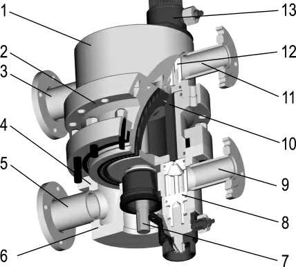
In PER,three main processes usually happen at least once per rotor revolution:charging process,cooling process and discharging process.In charging process,high total pressure gas from HP port,shown in Fig.1,is exposed to a lower pressure"virgin"passage fromt=0tot=tjet.As the virgin passage gradually opens to inlet port,compression waves,eventually steeping into a shockwave,form at the leading end of the passage and move into the passage.This shockwave is followed by contact face between the driving gas and the driven gas.The driven gas in rotor passage is compressed by shockwave,and leaves the rotor passage to HT port with high temperature.
In cooling period,the high temperature gas from HT port can decrease total enthalpy through heat exchanger.And the left side of rotor passage is gradually closed by trailing wall of HP port;the low temperature gas behind contact face expands further to ahieve lower temperature.The width of HT port should be designed properly so that rotating passage closes just as the contact face reaches the right end of the rotor passage.

Fig.1 An original pressure exchanging refrigerator
In discharging process,after cooled,the gas with high temperature getting medium controllable values re-feeds into the wave rotor passages where the cold stream expands to discharging port at the same time.This ends the whole cycle.
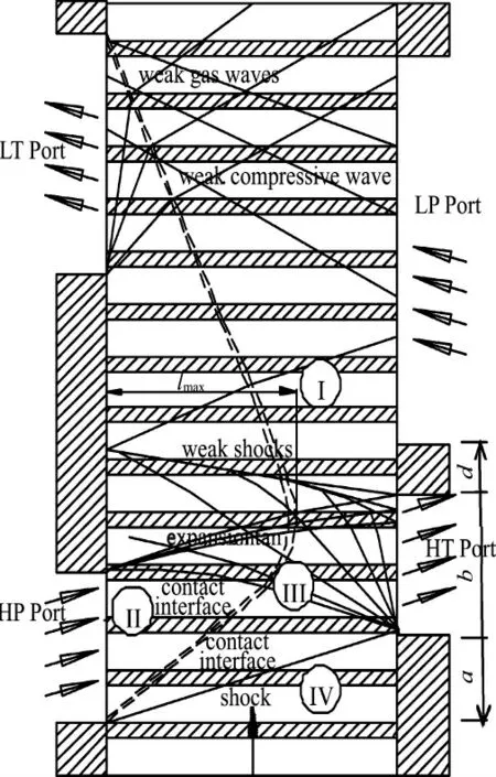
In charging process,shock-tube-type flow consists of the Region II,III and IV in the wave diagram,shown in Fig.2.The gas flows at a Mach number of 1from the jet.In the last process,the flow is isentropic.

Fig.2 Wave diagram of PER
There are many factors that influence refrigeration efficiency,such as rotor channel lengthl,offset angle between HT and HP ports,walls widthb,din Fig.2,and pressure ratio,revolution velocitynand so on.All these variables influence refrigeration performance by impacting on shockwave,expansion wave and contact face in passages of PER.
2 Wave diagram of PER and flow pattern in rotor passages
2.1 One-dimensional unsteady theory study on PER
As stated earlier,shockwave should enter the outlet nozzle,while contact face remains in the rightmost rotor channels so that PER operates normally.So contact faces and shockwaves must be tracked precisely.Their intension and move behaviors are the determinant factors that affect refrigeration performance.
The transit time of shockwave and contact face should match rotor revolution speed.Assume rotor slipping linear velocity

whereRis rotor pitch circle radius,then a basic limitation of PER on the two discontinuities can be depicted in wave diagram:

Time intervalst0,t1andt2are the time thresholds:

The structural sizes likea,banddare shown in Fig.2.
During the charging periods the flow pattern within the rotor passage is the same as that of shock tube which is initiated by a sudden rapture of diaphragm separating a high-pressure gas from one at low pressure.Following this rational line one can calculate the contact face velocity and shockwave velocity.Shock Mach numberMascan be calculated by initial stagnation pressure ratiopio:

And the velocity of contact facevfcan be calculated by the following equation:

Pressures on both sides of the contact face are continuous:

Temperature behind contact face is calculated by isentropic relations and that in front of contact face is calculated by

Some results from different pressure ratios of HP to LT port are listed in Tab.1with air as process fluid.
The limitation inequation(2)of PER can be drawn as lines in wave diagram.Line slopest0/l,t1/l,t2/lform upper or lower bounds of contact face and shockwave.To operate normally,the shockwave line must be located between linet0/land linet1/l,and contact face located between linet1/land linet2/l.Any other cases listed in Tab.2will adversely affect refrigeration performance.

Tab.1 Zone parameters at different pressure ratio pio

Tab.2 Representative abnormal cases of PER
2.2 Numerical study of PER
Although analytical approaches can provide some useful design parameters for a preliminary design,for a complete design,a whole-cycle analysis is required.A CFD model of wave rotor can help predict the wave timing within the rotor passages and the distribution of flow variables in the stationary port region[5].In this part,an experimental PER has also been modeled.The inlet port spans only one passage at a given time.The HP port is perpendicular to rotor passages.A 9mm(long)×7mm(wide)portion of the inlet port is resolved by a 81×101 stretched grid.The rotor passages are 9 mm(wide)×250mm(long)and each of the 64rotor passages is resolved by a 151×15stretched grid.The rotor spins at 2 900r/min.The HP port,HT port and the moving rotor passages are resolved on multiple structural uniform grid blocks sized 0.05 mm×0.05 mm.The port pressure ratiopio=1.75.
The centrifugal force is neglected by spanning circularly to model the rotor passages and static ports inx-ycoordinates.Leakage flows,both from rotor passages to the space between rotor and outer casing,and from passage to passage,are not yet included in the model.Fluid-to-wall heat transfer is also neglected as the blades separating the passages are treated as adiabatic surfaces,where working fluid is treated as a thermally perfect gas.
The finite-volume forms of unsteady,compressible 2-D Navier-Stokes equations with precondition(see Lit.[6])are integrated over time using a second-order accurate,4-stage Runge-Kutta explicit scheme.The convection term scalar gradient at the cell interface uses Green-Gauss node-based gradient evaluation originally proposed by Holmes,etal.[7]and Rauch,etal.[8].The inviscid flux terms are computed by using a new flux-vector splitting scheme called Advection Upstream Splitting Method Plus (AUSM +)[9,10]from Liou,etal.[11]which has several desirable properties—providing exact resolution of contact face and shockwave and free of oscillations at stationary and moving shocks.The inviscid flux terms are discretized by using cell interface primitive variables set by third-order MUSCL type interpolation without any flux-limiter.The diffusion terms are central difference.
Fig.3 shows the numerical results of static temperature(a)and pressure(b)contours in a PER passage att=0.6ms.As expected,when HP port opens to rotor passages,the highpressure gas starts compressing the low-pressure one in the passage by generating compression waves.These waves form a stronger single shockwave running through the passage at velocity ofvs.Furthermore,it is found that there is large temperature difference between frontal and back contact faces.The obvious thermal separating effect shows the feasibility of PER.

Fig.3 The contact face and shockwave in a rotor passage(t=0.6ms)
The moving velocity of shockwave and contact face can be directly achieved from CFD results.It is interesting that the CFD results are almost consistent to those from shockwave pipe theory in spite of the discrepancy of temperature difference.It saves much time because of the low computation cost of one dimensional unsteady theory.
To get high refrigeration efficiency,there should be a maximum distancelmaxfor contact face to reach rotor passages.When designing such a refrigerator,one should leave a certain space for contact face,i.e.thelmaxis smaller than the passage lengthl.Thelmaxis concerned with many parameters,such as rotor revolving speed,differential pressure between LT and LP ports and the gas properties,etc..
3 Experimental study of PER
As mentioned in former context,factors influencing the refrigeration efficiency can be categorized to structural parameters,such as rotor passage length,offset angle between HP and HT ports,ports width,etc.,and operating parameters,such as pressure ratio,revolution velocity and so on.All these parameters are tested in DUT GWRSDC.
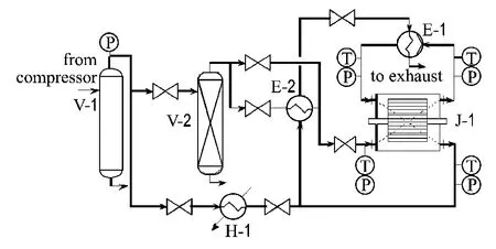
Fig.4 shows the schematic view of the experimental rig.Experimental gas —compressed air,from tank V-2,enters HP port of PER with temperature controlled by plate heat exchanger E-2valve and bypass pipe valve.High temperature gas leaves from HT port and is cooled by plate heat exchanger E-1.Refrigerated gas coming from LT port of PER is used for the cold stream of exchanger E-1,E-2 and is discharged into atmosphere through a trumpet type silencer.All ports′pressure can be controlled by the four valves of PER.The revolving speed of driving motor is controlled by frequency converter.The converted frequency which will be shown in next figures (times 60.0)will get the rotor revolution speed.All temperature and pressure signals acquired by transducers are transferred to computer automatically to save the real-time values every second.

Fig.4 Schematic diagram of the experimental arrangement
3.1 Pressure ratio
The pressure ratio not only determines shockwave′s intensity,but also changes its velocity and that of contact face,so it plays an important role in refrigeration performance.Fig.5 shows the isentropic efficiency versus rotation speed at pressure ratio 3.0and 4.7.The rotor length is 400 mm and offset angle between HP port and HT port is 10°.

Fig.5 Isentropic efficiency versus rotation speed with different pio
In natural gas light hydrocarbon reclaiming process,the isentropic efficiency which equals the real enthalpy difference dividing that in isentropic process is often used.

The experimental air is treated as perfect gas whose specific heat capacity at constant pressurecp=γR/(γ-1)remains constant.So the isentropic efficiency is calculated by

wherepioandTioare the pressure ratio and temperature ratio between inlet and outlet.
For a given structure,within a large scope,the higher pressure ratio often gives higher refrigeration efficiency at the same rotational speed.This is because with larger pressure ratio,the shockwave is strengthened and results in more complete thermo-separation,which can also be seen in Tab.1;and it can produce lower temperature at outlet port.But the larger pressure ratio means larger entropy production,so there is a decline trend in refrigeration efficiency.
3.2 Channel length,revolving speed and offset angle
Channel length determines the last time when shockwave and contact face transfer from HP jet to HT port.Despite of none influence on the shockwave intensity or temperature difference,the rotor length has indirect impact on the flow pattern through the gas wave reflections.According to the operating principle of PER,the channel lengthlsatisfies Eq.(2).At the given pressure ratio and revolving speed,it also has an optimum value just as revolving speed has an optimum value with given pressure ratio,channel length and offset angle.
The offset angle(a structural parameter)and the revolving speed (an operating parameter)determine the upper and lower time limits during which the gas waves transfer in the rotor channels.For the same reason described before there also is an optimum value at other given structural and operating parameters.
Fig.6 shows the relationship of the isentropic efficiency versus rotation speed at pressure ratio 4.0 with different offset angles.For the same offset angle there is an optimum revolving speed.

Fig.6 Isentropic efficiency versus rotation speed at pressure ratio 4.0with different offset angles
It is meaningless to test single parameter among channel length,offset angles,revolving speed and even the pressure ratio for their strong coupling.
All these parameters determining the precise timing of pressure waves follow the requirement as described by Eq.(2).In the case of much faster revolving or shorted channel length,the shockwave often reflects on leading wall of HT port,so the separated cold zone is recompressed or reheated by the reflective shock,just as the case No.1listed in Tab.2.
3.3 Incidence angle at inlet jet
Because the wave rotor passages gradually open to and traverse the inlet port,curved pressure waves followed by contact face emanate from the opening and the waves transfer into the passage and reflect from the trailing wall to interact with the contact face and other incoming pressure waves and eventually a clockwise oriented vortex at the spiral interface is produced.Eidelman[12]and Larosiliere[13]have testified that the gradual opening process significantly impacts the flow pattern and leads to a significant distortion of the fluid interface in the passage-to-passage plane and also a finite time for the formation of the shock.All these events can adversely affect the performance of a wave rotor.
Incidence angleβ,as shown in Fig.7,has significant impact on the distortion of contact face(see Fig.3(a))as well as Coriolis and centripetal acceleration,etc..Aimed to find the influence of the incidence angles on refrigeration performance,two inlet ports with incidence angle 0°and 10° were designed.The 10°is chosen to match circumferential component of jetting velocity to linear velocityvcof rotor passages based on an incidence loss model[14].

Fig.7 The velocity triangle in inlet jet
Fig.8 is the experimental isentropic efficiency with different rotation speed and incidence angles.There is about 2%-3%advancement on isentropic efficiency with incidence angle 10°.So the incidence angle plays an important role in refrigeration performance.

Fig.8 The isentropic efficiency versus rotation speed with different incidence angles
4 Conclusions
A novel compressed gas refrigeration technology using wave rotors as main working parts is briefly put forward.The pressured gas exchanging refrigerator realized the thermal separation through transfer of gas waves in rotor channels.The working process and refrigeration principle are first investigated by means of onedimensional unsteady flow theory and the fluidic pattern of PER is analyzed by means of computational fluid dynamics.All the main factors and most structural details that determine refrigeration performances are also experimented.The experimental results conducted in GWRSDC laboratory show the feasibility of developing PER.All the experimental phenomena can be explained by using the analytical results.
[1] AKBARI P,NALIM R,MUELLER N.A review of wave rotor technology and its applications [J].Journal of Engineering for Gas Turbines and Power,2006,128:717-735
[2] AKBARI P,KHARAZI A A,MLLER N.Utilizing wave rotor technology to enhance the turbo compression in power and refrigeration cycles[C]//IMECE 2003:Proceedings of International Mechanical Engineering Congress and Exposition.Washington D C:IMECE,2003
[3] KHARAZI A A,AKBARI P,MLLER N.An application of wave rotor technology for performance enhancement of R718 refrigeration cycles [C] //AIAA 2004:2nd International Energy Conversion Engineering Conference.Rhode Island:AIAA,2004
[4] AZOURY P H.Engineering Applications of Unsteady Fluid Flow[M].New York:Wiley,1992
[5] WELCH G E,CHIMA R V.Two-dimensional CFD modeling of wave rotor flow dynamics[C]//AIAA 1993:29th Joint Propulsion Conference and Exhibit.Monterey:AIAA,1993
[6] EDWARDS J R,LIOU Meng-sing.Low-diffusion flux-splitting methods for flows at all speeds[J].AIAA Journal,1998,36(9):1610-1617
[7] HOLMES D G,CONNELL S D.Solution of the 2D Navier-Stokes equations on unstructured adaptive grids[C]//AIAA-1989:AIAA Computational Fluid Dynamics Conference.Washington D C:AIAA,1989
[8] RAUCH R D,BATIRA J T,YANG N T Y.Spatial adaption procedures on unstructured meshes for accurate unsteady aerodynamic flow computations[C]//AIAA 1991-1106:32nd AIAA/ASME/ASCE/AHS/ASC Structures,Structural Dynamics,and Materials Conference.Washington D C:AIAA,1991
[9] CHIMA R V,LIOU Meng-sing.Comparison of the AUSM+and H-CUSP schemes for turbo machinery applications[C]//AIAA-2003:16th Computational Fluid Dynamics Conference and the 33rd Fluid Dynamics Conference and Exhibit.Orlando:AIAA,2003
[10] LIOU Meng-sing.A sequel to AUSM:AUSM +[J].Journal of Computational Physics,1996,129:364-382
[11] LIOU Meng-sing,STEFFEN C J JR.A new flux splitting scheme [J].Journal of Computational Physics,1993,107:23-39
[12] EIDELMAN S.The problem of gradual opening in wave rotor passages [J].Journal of Propulsion,1985,1(1):23-28
[13] LAROSILIERE L M.Three-dimensional numerical simulation of gradual opening in a wave rotor passage [C] //AIAA 1993-2526:AIAA/SAE/ASME/ASEE 29th Joint Propulsion Conference and Exhibit.Monterey:AIAA,1993
[14] PAXSON D E.An incidence loss model for wave rotors with axially aligned passages[C]//AIAA 1998-3251: AIAA/ASME/SAE/ASEE Joint Propulsion Conference and Exhibit.Cleveland:AIAA,1998
