Quasi Ellipsoid Gear Surface Reconstruction Based on Meshless Local Petrov-Galerkin Method and Transmission Characteristic
2010-03-01WUXuemeiSHANDebinandLIGuixian
WU Xuemei , SHAN Debin and LI Guixian
1 School of Mechanical and Electrical Engineering, Harbin Institute of Technology, Harbin 150006, China
2 School of Materials Science and Engineering, Harbin Institute of Technology,Harbin 150006, China
1 Introduction
With the rapid development of science & technology and modern production technology, mechanical transmission requirement is increasing, special transmission gears such as quasi ellipsoid gear with high precision, great intensity,good rigidity, little return difference and so on are demanded more frequently[1].
Complicated tooth profile and motion are the main characteristics of special transmission gears. The simulation of special gear must be based on discrete and reconstruction of the surface, while available software can not provide the technology of complicated surface reconstruction for special transmission simulation. It is difficult to establish the finite element analysis model of gear tooth with direct contact. When tooth meshing, the contact region must be refined. Thus, contact region refinement will increase the computer memory consumption significantly. Because of the complicated surface of the special gear, and the model can not be simplified, so three-dimensional solid unit meshing must be carried out. However, element and node information will increase with geometric series. It is difficult to provide sufficient memory for a general purpose computer[2–3]. So the problem that how to ensure the accuracy of the calculations and to reduce resources consumption becomes a key for the use of the finite element method to solve the problems of contact between gears.
The meshless method is a new numerical computational method developed in recent years. Compared with finite element method (FEM), the main benefit of the method is that the approximation field function is constructed entirely in terms of arbitrarily placed nodes of structures without using explicit mesh. And the meshless method shows obvious advantages in treating with special transmission 3D model simulation analysis and contact analysis problems because the method gets rid of the reliance on the mesh and provides continuous and flexible field function.
Nowadays element-free method mainly include element-free Galerkin method (EFG), reproducing kernel particle method (RKPM), finite point method (FPM),partition of unity method, point interpolation method(PIM),meshless local Petrov-Galerkin (MLPG) method,meshless weighted least-square method[4–7], and so on,among these methods, MLPG method fully develops superiority of local Petrov-Galerkin method. Furthermore,MLPG method employs natural neighbour interpolation to construct the trial function, accordingly essential boundary conditions can be imposed accurately. Linear finite element form function is employed, so the integrand function order is reduced and higher numerical integration precision can be obtained by using fewer integration points. In general,MLPG method is a simple and practical method, its efficiency and precision is excellent[8].
In this paper, the MLPG method is employed, making the tooth surface discrete into limited points (sparse point cloud data or meshes), reconstructing three-dimensional model of the tooth surface while doing a concrete analysis.
2 Working Principle of Quasi Ellipsoid Gear
As shown in Fig. 1, a pair of spherical gears used in flexible wrist of robot is quasi ellipsoid gears, which has three degrees of freedom at the same time. Fig. 2 shows that convex teeth and concave teeth are evenly arranged on two local spheres of quasi ellipsoid gear.
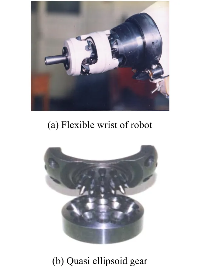
Fig. 1. Quasi ellipsoid gear
In general, the gear with the convex teeth gear is driving gear, the gear with concave teeth is driven gear. When driving gear rotates or swings around rotation center,convex teeth 2 on the gear 1 and concave teeth on gear 3 mesh each other, the driven gear 3 rotates or swings also. It is clear that such transmission can achieve omni-directional movement[9–10].
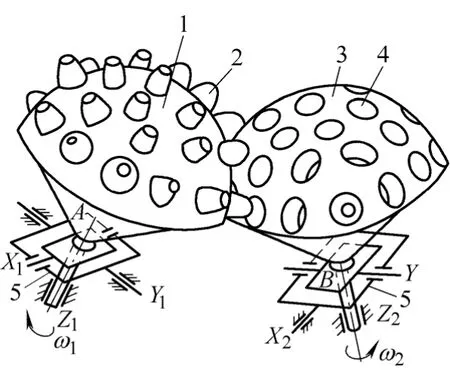
Fig. 2. Quasi ellipsoid gear sketch
3 Surface Discretization of Quasi Ellipsoid Gear
To achieve the dynamic simulation of the tooth surface,intensive mesh or dense points cloud is the necessary condition. Intensive mesh requires a large amount of storage space, and solving the problem of power requires a large amount of calculating time, particularly for the high non-linear contact analysis[11]. Different from other methods of surface reconstruction, meshless method of surface reconstruction completes with the moving least squares method. The method has a moving interpolation function, and can reconstruct and refine local surface flexibility. Because of small amount of calculation, simple and flexible, thus meshless method is suitable for dynamic simulation of complicated surfaces.
3.1 Tooth surface equation of quasi ellipsoid gear
Because of quasi ellipsoid gear transmission can achieve three-dimensional space omni-directional movement, tooth surface equation of quasi ellipsoid gear is complex[10]. For the purpose of achieving the dynamic simulation, the surface must be discretized and stored in computer procedures in the way of mesh or points cloud.
3.2 Concave tooth surface discretization
After coordinate transformation, the tooth surface must be discretized in local coordinates of the tooth surface. The convex tooth surface of quasi ellipsoid gear is a surface of revolution with a radius R and arc generatrix[12]. So the convex tooth surface will be simply discretized in local coordinates. Thus more complicated concave tooth surface is discretized in the paper.
Concave tooth surface is a complex three-dimensional surface, similar to a surface of revolution surface. Shown in Fig. 3, the surface will be discretized into rectangular cross-latitude meshes.
First of all, using a plane to cut through Z-axis on the tooth surface, and parallel is the intersection line of two planes, so we can get N parallels. Then using the plane parallel to coordinate plane with the xOy, we will get M meridians. Among parallels and meridians, the two ends of the parallel are composed of endpoints of meridian. The surface is discretized into meshes of N multiply M (shown in Fig. 4) .
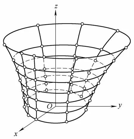
Fig. 3. Discretization of concave teeth flank
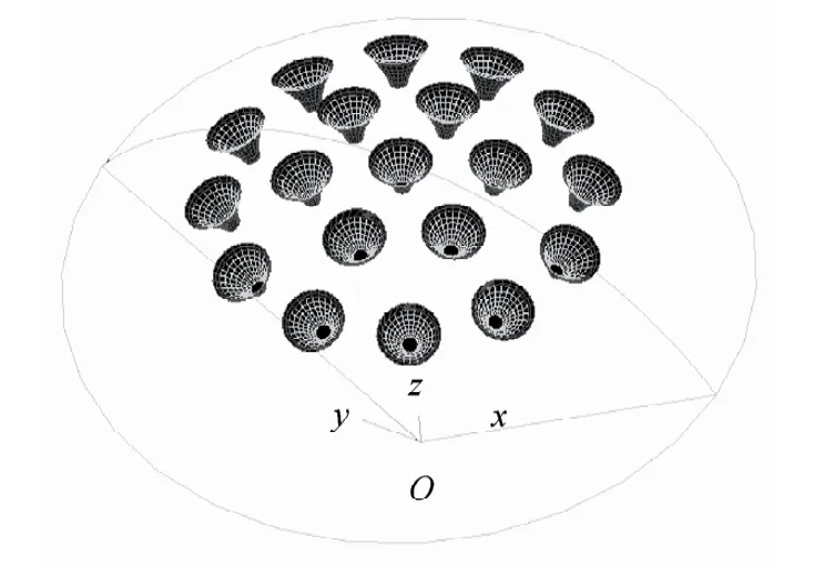
Fig. 4. Discrete result of concave teeth flank
4 Surface Reconstruction with Mesh-Free Method
The tooth profile surface discretized is composed of little nodes. In order to get precise movement and dynamical simulation results, reconstruction of local surface is needed,that is to reconstruct a prototype of the tooth profile.
In the local coordinate, the tooth profile surface can be constructed with latitude and longitude, as shown in Fig. 3.Meridian interpolation should be used first before using parallel interpolation.
4.1 Meridian interpolation based on meshless method
The point “×” shown in Fig. 5 is to be interpolated, and the point “×”is obtained by the node “O” with the moving least squares method. The circle whose center is the interpolation point is called the domain, and radius R for the domain. The radius must ensure that more than three nodes of non-collinear are in the domain.
We assume that function value of the surface yiis known,whereiy is the value of interpolation points function y (z)about the nodeInterpolation points y (z) in the domain can be defined as[13]
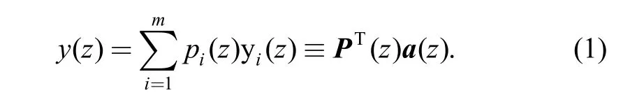
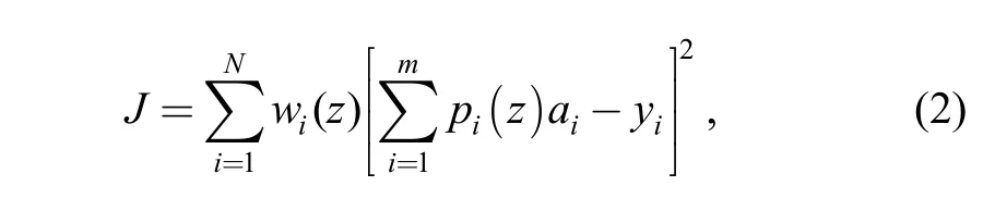
Let J be minimum, that is
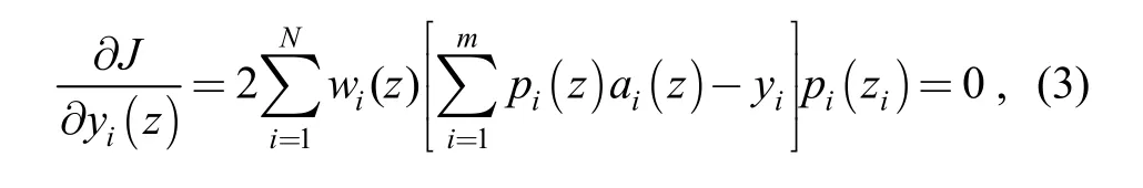
we have
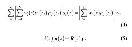
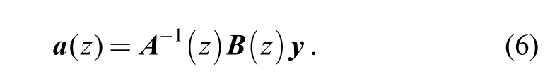
We can get undetermined coefficient vector a(z) from Eq. (5):
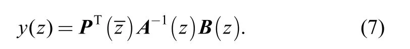
From Eq. (1) and Eq. (6), we get
4.2 Parallel interpolation based on mesh-free method
Different from the meridian interpolation, the shape of parallel is similar to round and parallel interpolation will be much better in polar coordinates. As shown in Fig. 6, radial coordinate of interpolation point can be obtained by the moving least squares method with 3 to 4 points in domain.The domain of interpolation points is an-shaped field, and interpolation points in the domain can be similar to
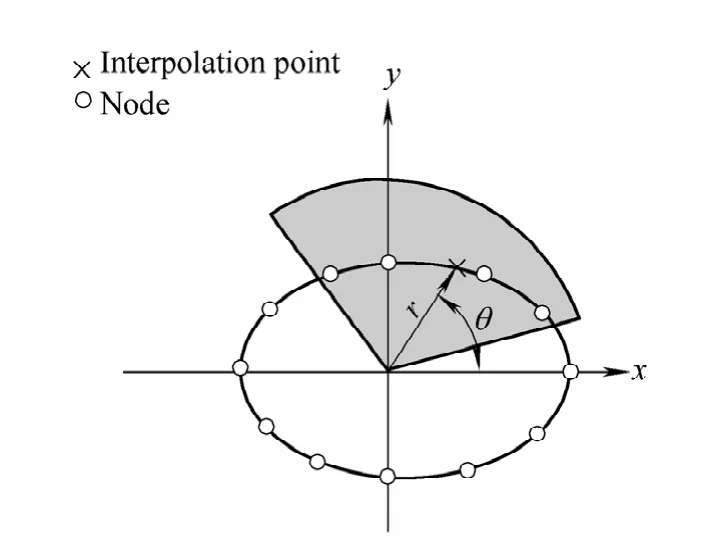
Fig. 6. Latitude line interpolation by MLPG method
After the interpolation in both directions of meridian and parallel, concave teeth flank is reconstructed by intensive points, so we can obtain the reconstruction result of quasi-ellipsoid gear as shown in Fig. 7.
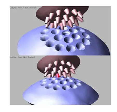
Fig. 7. Quasi ellipsoid gear reconstruction result
In the example, the basic parameters of quasi-ellipsoid gear are as follows:
a —Center distance, a=112 mm,
m —Module, m=3 mm;
R —Fixed radius of concave teeth sphere, R= 77.8mm.
5 Interpolation Precision Analysis of Tooth Profile Surface
For the purpose of verifying the precision of Interpolation, a meridian and a parallel are analyzed respectively. Analysis and comparison have been done between the original data and interpolation data, the relative error is given as[15]
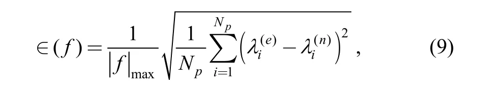
where ∈( f) is the overall error of function,
Np—Number of nodes,
Fig. 8 shows the interpolation error of the meridian and parallel. As the tooth surface is constituted by crossing lines of the meridian and parallel, interpolation precision of meridian and parallel is just the surface interpolation precision. We can see that the error is zero nearly as the nodes increasing, which illustrates a high precision interpolation.
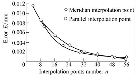
Fig. 8. Interpolation converge process and error
6 Simulation Calculation of the Transmission Ratio Based on Adams 2003
Compared with Adams R12, Adams2003 has a calculating capability of contact, which can accurately calculate the gear contact condition. But the software simulation is built on the basis of discrete surfaces, and can not refine surface flexibly in the process of solving. So a higher level of the original surface is required.
As Adams does not have the complex three-dimensional surface modeling capability, the surface reconstruction is carried on in the three-dimensional modeling software,Solidworks, using the above method and meshless method.The surface is imported into Adams by Parasolids graphics formats, as shown in Fig. 9.
In order to ensure the process of meshing gears smooth and reliable, a small torque is imposed on driving gear and damping torque is imposed on driven gear in Adams.
Transmission ratio in the process of meshing can be got through the simulation in Adams. The theoretical transmission ratio is
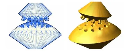
Fig. 9. Quasi ellipsoid gear introduced into Adams software
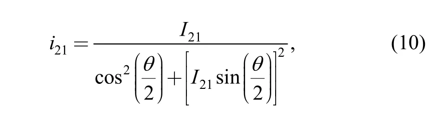
where I21— Nominal transmission ratio,
θ — Rotational angle, arc.
Fig. 10 shows the transmission ratio comparison between the theoretical calculation and simulation result.
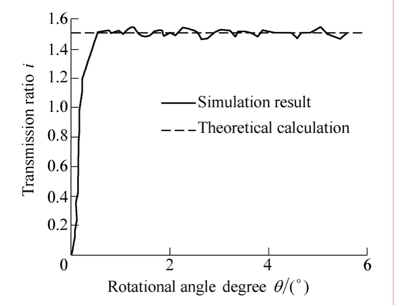
Fig. 10. Transmission ratio comparison
We can see that the transmission ratio of simulation agrees well with the theoretical calculation. However, the transmission ratio of simulation has bigger fluctuation and the contact calculations are inaccurate in the process of surface simulation. So it is indicated that the reconstruction of local surface is very important in the process of calculation.
7 Conclusions
(1) The quasi ellipsoid gear reconstruction model is obtained.
(2) Tooth meshing simulation has been done. Simulation calculation is reduced enormously, so special gears simulation can be realized by minitype computer.
(3) Simulation transmission ratio is obtained, compared with theoretical transmission ratio, the result inosculate preferably.
(4) The method can also be used in reverse engineering of special gears.
[1] WEN Jianmin. Study on noninvolute beveloid gears transmission[D]. Harbin: Harbin Institute of Technology, 2004:1–5.(in Chinese)
[2] CHEN T, RAJU I S. Coupling finite element and meshless local Petrov-Galerkin methods for two-dimensional potential problems[J].Comput. Method. Appl. Mech. Engrg, 2003(192): 3 550–4 533.
[3] LANCASTER P, SALKAUSKAS K. Surfaces generated by moving least squares methods[J]. Math. Comput, 1981, 37(155):141–158.
[4] CHEN Li,CHENG Yumin. Reproducing kernel particle method with complex variables for elasticity[J]. Acta Mechanica Sinica,2008 , 57 (1): 1–10. (in Chinese)
[5] ZHENG Baojing, DAI Baodong. Improved meshless local Petrov-Galerkin method for two-dimensional potential problems[J].Acta Mechanica Sinica, 2010, 59(8): 5 182–5 189. (in Chinese)
[6] ZHANG Xiong, HU Wei, PAN Xiaofei, et al. Meshless weighted least-square method[J]. Acta Mechanica Sinica. 2003, 35(4):425–431. (in Chinese)
[7] CAI Yongchang, ZHU Hehua, WANG Jianhua. The meshless local Petrov-Galerkin method based on the Voronoi cells[J]. Acta Mechanica Sinica, 2003, 35(2): 187–193. (in Chinese)
[8] CHEN Shenshen, LIU Yinghua, CEN Zhangzhi. A meshless local Petrov-Galerkin method for static shakedown analysis of elasto-plastic structures[J]. Chinese Journal of Theoretical and Applied Mechanics, 2009, 41(5): 713–721. (in Chinese)
[9] LI Guixian. Meshing analysis on the quasi-ellpsoidal transmission with inner-toroidal teeth in the flexible joint of robot[J]. Chinese Journal of Mechanical Engineering, 1992, 5(2): 79–87.
[10] LI Guixian. Spatial geometry modeling and its application in engineering[M]. Beijing: Higher Education Press, 2007. (in Chinese)
[11] ZHANG Yan, WANG Jianguo, ZHANG Bingyin. Coupled FEM and meshless radial point interpolation method[J]. Journal of Tsinghua University (Science and Technology), 2008, 48(6):951–954. (in Chinese)
[12] LI Huamin, LI Guixian. The design and applycation of planet gear mechanism[M]. Beijing: China Machine Press, 2007. (in Chinese)
[13] ZHANG Xiong, LIU Yan. Meshless method[M]. Beijing: Tsinghua University Press, 2004. (in Chinese)
[14] [14] WANG Xucheng. Basic theory and numerical method of finite element method[M]. 2nd ed. Beijing: Tsinghua University Press, 2000. (in Chinese)
[15] [15] ATLURI S N, ZHU T. A new meshless local Petrov-Galerkin (MPLG) approach in computational mechanics[J].Computational Mechanics, 1998(22): 117–127.