Locating Error Considering Dimensional Errors Modeling for Multistation Manufacturing System
2010-03-01ZHANGFapingLUJipingTANGShuiyuanSUNHoufangandJIAOLi
ZHANG Faping, LU Jiping, TANG Shuiyuan, SUN Houfang, and JIAO Li
School of Mechanical Engineering, Beijing Institute of Technology, Beijing 100081, China
1 Introduction
Modern manufacturing systems involve multiple operations in multistation processes, during which several fixtures are used and locating datum change may be necessary. Each machining operation in such systems introduces machining errors which will propagate in succedent stations and cause other machining errors with the flow of the part in multi stations. Therefore, there is a complex non-linear relationship between final machining dimensional errors of part and characteristics of those multistation processes. Dimensional variation in these systems has been identified as a critical quality issue.Product-dimensional quality control, which includes variation propagation modeling, tolerance analysis and synthesis, and variation reduction during manufacturing phase, plays a critical role for the success of a manufacturing activity. However, the inherent complexity in these processes makes it very challenging to model and predict the stream of variation. Therefore, the stream-of-variation analysis (SOVA) has attracted more and more interest from both the industrial and academic communities in the last decade.
Error accumulated and propagated phenomena in multi station manufacturing process were first studied in automobile assembly process[1–3]. In order to detect and localize the root causes of variation in auto body assembly,knowledge-based diagnostic approach has been used[1].Furthermore, HU[3]concluded that the state space model is the right way to explicitly and effectively describe the dimensional errors’ flow and transformation in assembly lines. This approach is so-called the stream of variation(SOV) which is employed by series papers for error analysis in auto-body assembly lines. Later SOV model has been improved and used to control dimensional variation in multistation assembly lines by using the assembly station index as the time parameter in the model[4–5]. Those models facilitated the incorporation of vast control tools in solving problems in assembly quality. In general, SOV model is used for the identification and classification of root causes of assembly errors[6–7]. In addition, assembly errors control has been achieved by using the model[8–9].
More and more researchers have used SOV model to analyze dimensional errors in multi-manufacturing systems(MMS)[10–12]. Machining errors have been viewed as the states of a discrete linear time-varying system, whose output is the dimensional measurements of the part, and operation number as the time index[12]. HUANG, et al[13],dealt the variation transmission and diagnosis with the SOV theory. Similarly, with the use of the model in assembly lines, strategies of machining errors control have also been adopted[14–17].
It should be noticed that although researches related to SOV model have been conducted in machining error depiction and control, yet the explicit expression of the deviation influence of locating parameters and locating datum on final dimensional errors were not provided. This is the reason why we rehandle the SOV modeling and give linear explicit expressions of process characteristics on the dimensional errors.
The remainder of the paper is organized as follows.Section 2 gives the linear state space modeling procedures with special concern about the influence of the errors in locating parameters and locating datum on the dimensional variations. The dimensional error calculation methodology is given in section 3. A simple two-dimensional example is used to illustrate the implementation of the newly proposed method in section 4. Manufacturing industrial car gear box cover is used to validate the procedure in section 5. Finally,the conclusions of the paper are given in section 6.
2 Linear State Space Modeling of the Dimensional Errors
2.1 State space modeling
2.1.1 Machining features and its expression
Here three coordinate systems are defined in derivation of the state space model. They are global coordinate system(GCS), locating coordinate system(LCS), and workpiece coordinate system(WCS). GCS denotes global coordinate system which provides reference for other coordinate systems and can be chosen arbitrarily. LCS denotes locating coordinate system determined by the position of fixture elements in each machining station. WCS denotes workpiece coordinate system which is fixed in the workpiece and moves with it through different setups. And each coordinate system is denoted by its origin and three coordinate axes. The three coordinate axes are determined by the right-handed orthogonal basis vectors x, y, z,respectively.
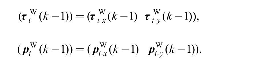
A part feature parameter i, i = 1, 2, …,n, in the coordinate system WCS at the machining station k, k = 1, 2, …,N, can be represented as

where n denotes the total number of machined features, C denotes the type of the feature, N denotes the total number of machining stations; τ denotes the feature orientation vector, p denotes the feature location vector, and d denotes the feature dimension parameters vector. The right superscript W indicates the variable is in coordinate system WCS. The denotation above is somewhat similar to the feature representation in general CAD system, and makes it easy to get data from CAD system. Furthermore, the entire part feature parameters at station k can be denoted by the following vector
So dimensional machining errors after operation k can be represented by

Similarly, errors in the vector of fixture element positions in coordinate system GCS are defined as:
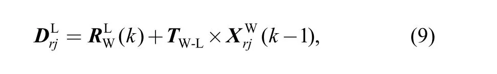
During operation, the actual part feature is determined by cutting tool path which is stipulated in coordinate system GCS. So the part feature emerged at station k in coordinate system GCS can be denoted as

Accordingly, the part feature representation in locating coordinate system LCS is
where the right superscript L indicates the variable is in coordinate system LCS. With the representation for individual part feature, the part can be modeled as a vector by stacking up all feature vectors, we have
in coordinate system GCS and LCS, respectively.According to the theory of coordinate transformation, part feature representation can be transformed from coordinate system LCS to coordinate system GCS as follows:
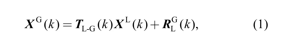
where TL-G(k) denotes the transformation matrix transforming vector representation in coordinate system LCS into the coordinate system GCS.denotes the representation of the origin of coordinate system LCS in coordinate system GCS. In the same way, part feature representation can be transformed from coordinate system WCS to coordinate system LCS as follows:
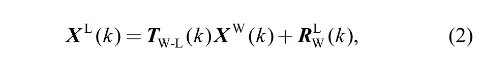
where TW-L(k)denotes the matrix that transforms vector representation in coordinate system WCS into that in coordinate system LCS, whiledenotes the representation of the origin of coordinate system WCS in coordinate system LCS.
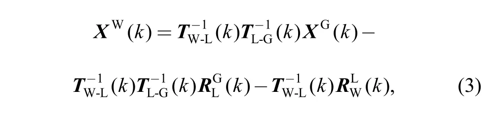
Combining Eq. (1) and Eq. (2) yields
The above part feature positions are nominal value where no actual errors are considered. Actually many factors will cause the deviation of workpiece feature during machining,therefore, the dimensional errors emerge. The emergence and stacking up of the dimensional errors can be described by SOV model. The following sections will give the derivation of the model.
2.1.2 State space model for MMS
State space model can be used to mathematically describe the relationship of process characteristics and final output, during which machining process is reckoned as discrete time-varying system, while the machining stage is used as time index and the dimensional errors are outputs.The model is usually written in the follow form:
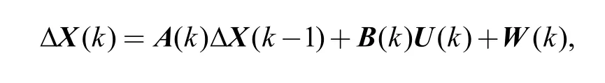
where ∆X(k) is the dimensional deviation vector of the k station, while ∆X(k−1) is that of the k−1 station. A(k) is the dimensional deviation state matrix which expresses how dimensional deviation vector ∆X(k) depends on the dimensional deviation vector ∆X(k−1). B(k) shows how error ∆X(k) depends on the newly introduced machining error U(k), and vector W(k) is employed to take into account the residuals after linearization and un-modeled effects.
Fig. 1 illustrates the multi-station machining system.The following sections will show the derivation of the state space model for multi-station machining system.
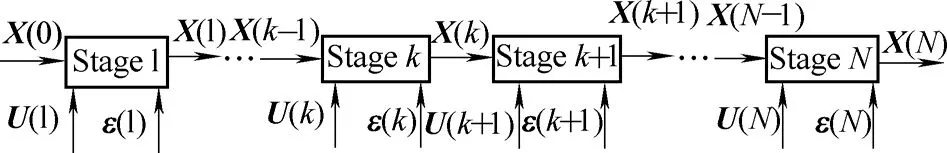
Fig. 1. Diagram of traditional multistation machining process
Actually, the position and orientation of coordinate system LCS in coordinate system GCS are determined by fixture parameters. In that situation TL-G(k)andwhich transform the expression of position and orientation of coordinate system LCS into coordinate system GCS, are determined by fixture parameters vector LG(k).Therefore,there exist functionsandsuch that
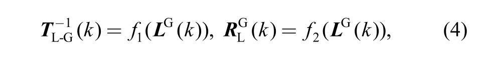
It should also be noted that previous machined features denoted asW( k −1),X especially those features used as locating datum, may cause a position deviation of workpiece and the attached coordinate system WCS in coordinate system LCS in the machining station where operation k is performed. In that situationW( k −1)X will cause dimensional errors. SoW( k −1)X will determine the transformation matrix TW-L(k)and the vectorwhich describe the orientation and position of coordinate system WCS in coordinate system LCS. Therefore, there exist functionsandsuch that

Substituting Eq. (4) and Eq. (5) into Eq. (3) gives
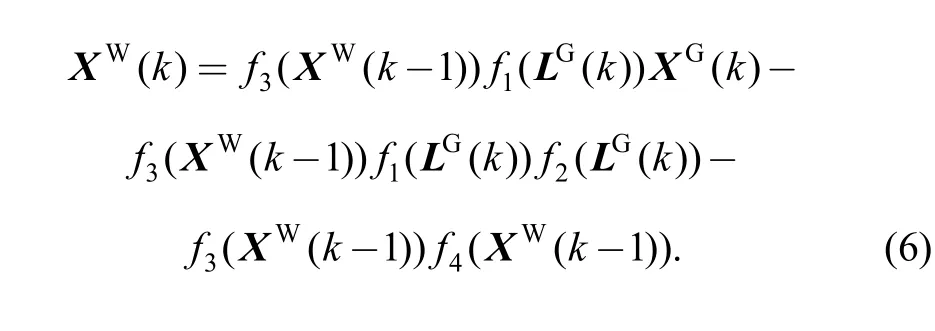
Differentiating Eq. (6) yields the variation stream model in the form of the state space equation:
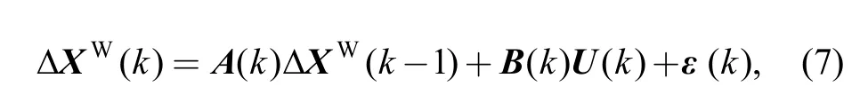
where
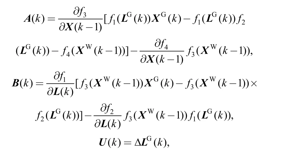
and vector ε(k) takes into account the residuals after linearization and un-modeled effects.
Eq. (7) is the linear state space model of dimensional variation in multi-station machining systems. A(k) is the state transition matrix and transforms process deviationto state vectorWhile matrix B(k)shows how errordepends on the newly introduced machining error U(k).
The key issue to establish Eq. (7) is to attain to the four expressionswhich will be formulated under the procedures in the following sections. According to the procedure, we can derive the above SOV model for most machining systems, provided that adequate CAD/CAPP data about the machining process are available. This makes the process plan evaluation possible prior to the real machining process conducted, so that it supports the optimum of process design.
It should be noted that the model mainly concerns about the characteristics of fixture parameters errors (locating parameter deviation), previous station machined features errors. We can employ the same procedure to establish the state space model concerning more other process control characteristics.
2.2 Influence of locating parameter deviation
The positions of the Nplocating pins Li, i = 1, 2, …,Np,at the k machining station can be described in the global coordinate system GCS as
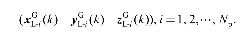
Position and orientation of the coordinate system LCS in the coordinate system GCS at machining station k are determined by the following vector
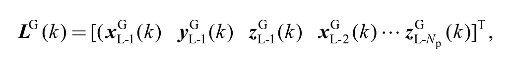
which is position of the fixture locating pins in coordinate system GCS.
According to Ref. [18], the three coordinate axes of coordinate system LCScan be expressed as
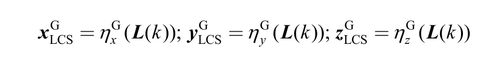
in coordinate system GCS in terms of the fixture parameters, and the transformation matrix can be obtained as follows:
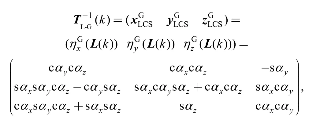
where αx, αy, αzdenote the orientation angles of coordinate axesof coordinate system LCS in coordinate system GCS, namely, the orientation of coordinate system LCS. cα means cosα and sα means sinα.The derivation of vectorscan be found in Ref. [18].
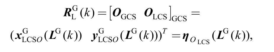
By the above transformation matrix, the orientation of coordinate system LCS in coordinate system GCS is achieved. The vectorrepresents the origin of coordinate system LCS in coordinate system GCS and can be expressed as a function of the fixture parameters as follows:
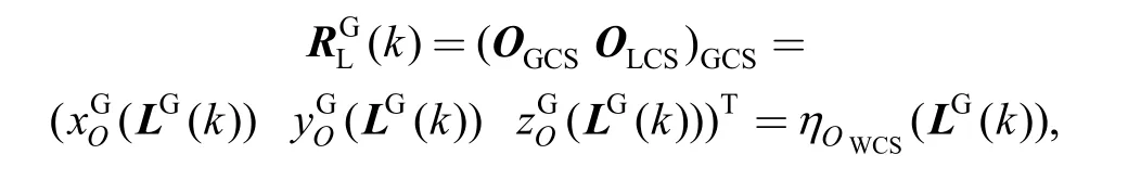
where OGCS, OLCSdenote the origins of coordinate system GCS and coordinate system LCS, respectively.can again be gotten from the results in Ref.[18]. Sohas been expressed by locating parameter LG(k).
2.3 Influence of locating datum deviation
Locating datum features used in the k station are certainly portion of the features machined in k−1 station.The errors of those locating datum features in the k station result in the position and orientation deviation of the coordinate system WCS in coordinate system LCS. Fig. 2 illustrates the relation of coordinate system WCS and the locating datum feature
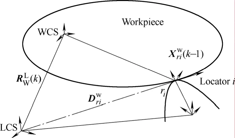
Fig. 2. Schematic diagram of a fixture-workpiece
As shown in Fig. 2, the position of the ith contact point between the ith locator and part in coordinate system GCS can be expressed as
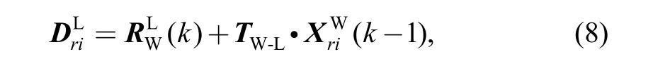
For determined location scheme, there are six locating points for traditional 3-2-1 scheme. By mathematic deduction, the following equation can be gotten as follows:
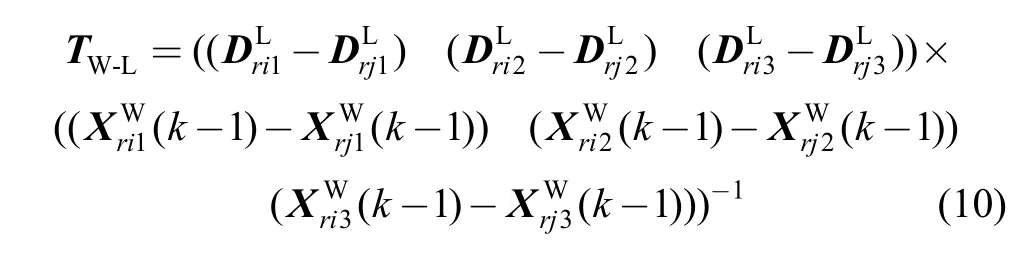
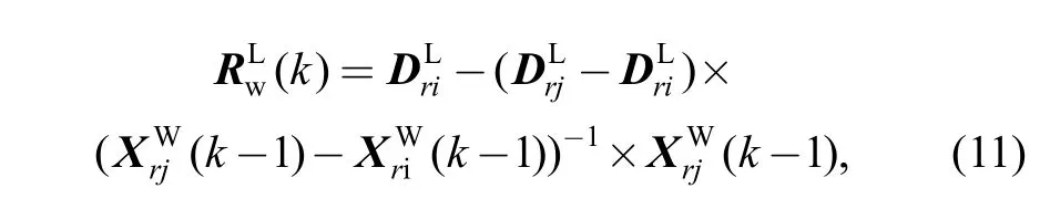
which is also the function of.Up to now TW-Landare expressed by.So the functions ofare achieved.
3 Calculation of Dimensional Errors
Dimension of two features is the relative position of those features, while the dimensional errors result from the deviation of those features from their nominal position respectively when machined. So the dimensional errors can be mathematically expressed as follows

where ∆d is a dimensional error of two features. If i=j, then∆d=0, where the errors from machine tool are not considered. And
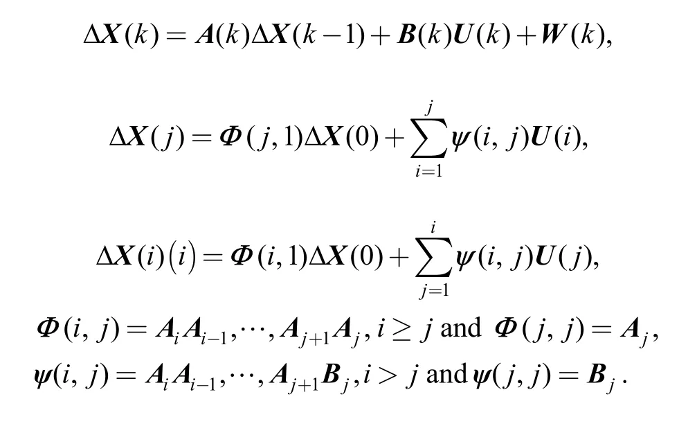
Where ∆X(j) denotes the parameter deviation vector of the features machined at the jth station, ∆X(i) denotes the parameter deviation vector of the features machined at the ith station; ∆X(0) is the initial deviation vector of the incoming workpiece.
4 A Simple Two-dimensional Example
A simple 2D example is employed to illustrate the procedure outlined in section 2. A rectangular part shown in Fig. 3(a) is machined at the fixture scheme shown in Fig.3(b). It is assumed that features 1 and 2 have been machined in previous stations and are used as the locating datum at this station. Feature 3 is machined in the station whose locating scheme is shown in Fig. 3(b). Fig. 3(c)demonstrates the setup of the workpiece and fixture system.The coordinate systems WCS, LCS and GCS are also shown in Fig. 3, respectively.
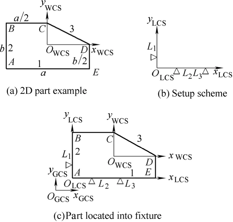
Fig. 3. Simple two-dimensional example
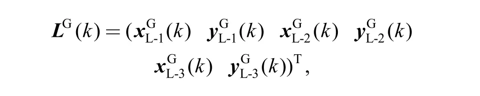
Fixture parameters in the global frame coordinate system GCS is labeled as
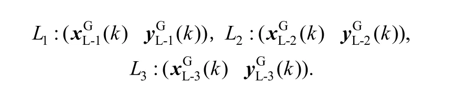
Therefore, the vector of fixture parameters is given as
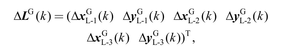
and the components of the deviation vector of fixture parameter errors are
Orientation and position parameters of the previously machined part features i=1, 2 expressed in coordinate system WCS are labeled as follows:
And nominally

In order to simplify expressions, the positions of features 1, 2, 3 are labeled by the vertices A, B, C on their respective features, just as follows:
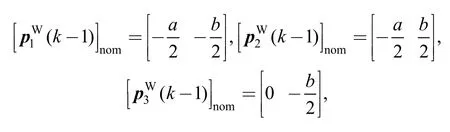
where a, b are the length of the features 1 and 2,respectively.
4.1 Influence of errors in fixture parameters
The calculation of this kind of influence is to establish the equation of coordinate system LCS denoted by the position of locating points in coordinate system GCS,which includes the denotation of the coordinate axes orientation and the original position of coordinate system LCS. Changes of position parameters of the locating elements result in the translation and rotation of coordinate system LCS, shown as Fig. 4.
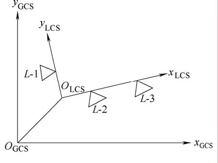
Fig. 4. Deviation of coordinate system LCS induced by errors in fixture
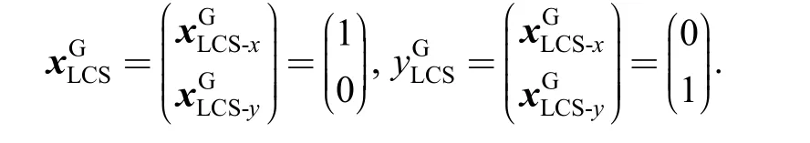
Two orthogonal basis vectorswhich determine the axes of coordinate system LCS, can be expressed in coordinates system GCS as follows:
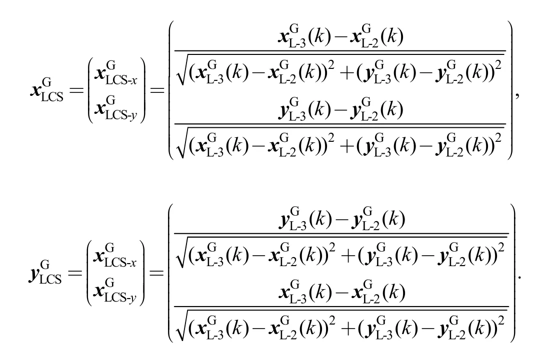
And nominally
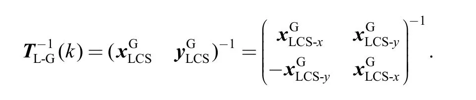
Following elaboration in section 2, we can get the transformation matrix from coordinate system LCS to coordinate system GCS as follows:
And nominally
Origin OLCSof the coordinate system LCS is at the intersection of the line passing through the locators L1and L2, and the line passing through L3, perpendicular to the line passing through L1and L2. Position of the point OLCSin coordinates GCS is given by the vector
In this condition we can determine functions
4.2 Influence of errors in locating datum feature
The previous machined features will influence machining errors when they are used as locating datum features, because errors in locating features cause the part and the attached coordinates system WCS to translate and rotate with respect to its nominal position and orientation.Modeling of this influence can be fulfilled by denoting the position and orientation of coordinate system WCS in GCS coordinates with the previous machined feature’s expression. Fig. 5 shows the rotation of coordinate system WCS induced by errors in locating datum features.
As shown in Fig. 5, the vectors xWCSand xLCSdetermine the x axes of coordinate systems WCS and LCS,respectively. And θx, which denotes the angle between the vector xWCSand the vector xLCS, is expressed as
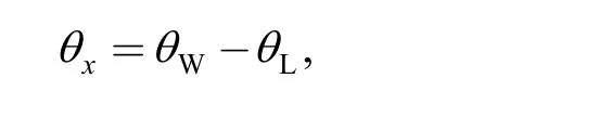
where θWis the angle between the feature 1 and the vector xWCS; θLis the angle between the normal vectorof the feature 1 and the vector xLCS. Since the feature 1 keeps contact with locating pins L2and L3, the normal direction of feature 1 should be consistent with that of the line determined by locating pins L2and L3. So θLis determined, and then we have
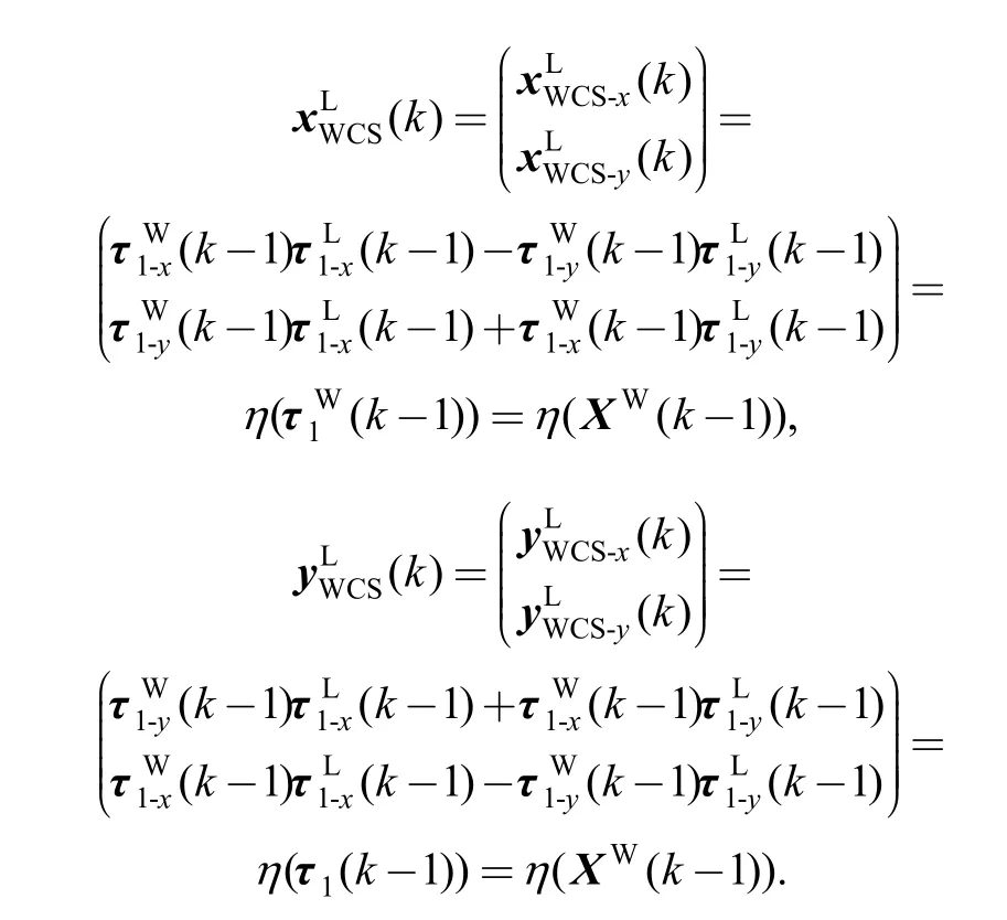
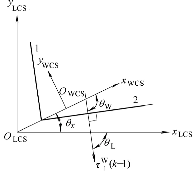
Fig. 5. Rotation of coordinate system WCS induced by errors of locating datum features
The transformation matrix transforming vector representation from coordinate system LCS to coordinate system GCS can be written as

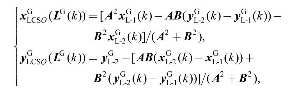
To express the position of the origin of coordinate system WCS in coordinate system LCS, the following procedures can be used. Origin of coordinate system WCS can be denoted by the vector
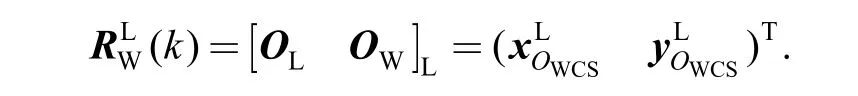
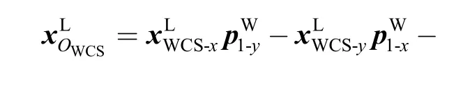
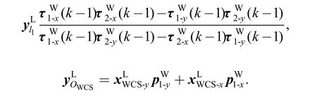
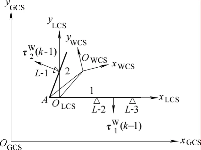
Fig. 6. Translation of the coordinate system WCS induced by errors of locating datum feature
The detail deviation is shown in appendix at the end of the paper. By now we also get the expressionandSo the functionsare formulated.
5 Analytical Case
The model derived in this paper is validated in the machining of a gear-box cover shown in Fig. 7. The part is machined according to the actual process plan in a factory.The process and locating datum features are identified in Table 1. After the last machining operation, all features were measured.
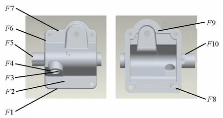
Fig. 7. Gear-box cover used to verify the model
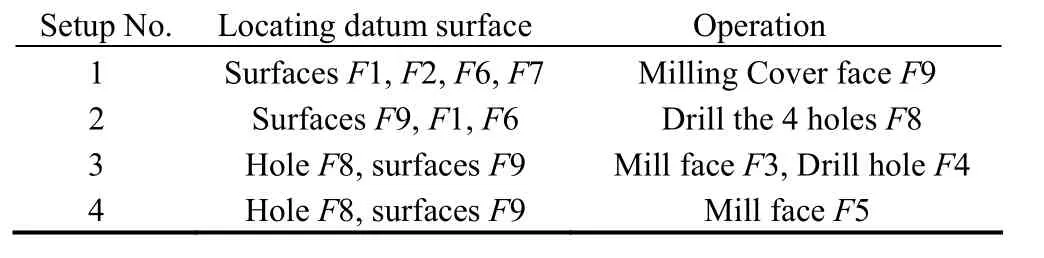
Table 1. Process plan for machining of the cover
As many as n = 5 features were machined in N = 4 machining operations shown in Table 1. Coordinate system WCS is determined by surface F6, axis of shaft F10 and Hole F4 of the part. Planes were described by a unit vector defining its orientation and one point in the plane defining its position, two orthogonal vectors defining its contour parameter. For hole feature, a local coordinate system is used that consists of three orthogonal unit vectors (e1, e2,and e3) and an origin. Those are somewhat like the feature definition in general CAD system.
The calculation of the example is operated in this way:first, workpiece parameters are extracted from CAD model established in CAD software Pro/Engineer by means of the developing tool Pro/toolkit. Then mathematic software MATLAB6.5 is used to fulfill the calculation.
Tables 2 and 3 show machining results of the cover.One cover was machined with all process parameters set to the nominal. The second cover was machined with 2 mm deviation of one of the fixture elements in setup 3. All the two machined parts were measured on a coordinate measurement machine(CMM) and the measurement results were compared with the model predictions. As can be seen from those tables, the results match well with the parameters of the actually measured features.
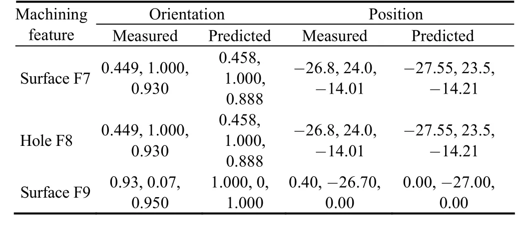
Table 2. Experimental result for the cover machined with all machining parameters set to nominal mm
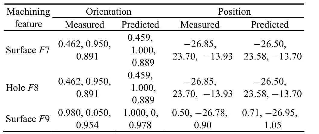
Table 3. Experimental result for the cover machined with a error set for a fixture mm
6 Conclusions
A general procedure to derive SOV is presented for dimensional machining errors in multi-station machining system. Main contributions of this research can be summarized as follows.
(1) A general procedure for modeling the effect of machining process characteristics on part feature dimensional errors during the multi-station machining process is presented.
(2) The linear state space form of the SOV model for multi-station machining system is formulated in which the influence of locating errors including deviations of locating parameter and locating datum errors are considered.
(3) The emergency and propagation of process characteristics induced error is explicitly depicted by the derived mathematical model.
By this way, process design verification is feasible in terms of error accumulation and transformation when the part passes the whole process, provided that the CAD/CAPP data are available.
These procedures are essential in derivation of the SOV model of dimensional machining errors. However, the modeling developments and researches are still in the academic period. Many more key control characteristics(KCC), such as the measure datum errors, force induced errors should be considered. Furthermore, based on the key product characteristics(KPC), KCC sensitive matrix should be formulated, which is out of the scope of this paper and is in next research step.
[1] Ceglarek D, SHI Jianjun, WU S M. A knowledge-based diagnosis approach for the launch of the auto-body assembly process[J].ASME, Journal of Engineering for Industry, 1994, 116(4): 491–499.
[2] ROAN C M, HU S J. Monitoring and classification of dimensional faults in automotive body assembly[J]. The International Journal of Flexible Manufacturing Systems, 1995, 7(2): 103–125.
[3] HU S J. Stream-of-variation theory for automotive body assembly[J]. CIRP Annuals-Manufacturing Technology, 1997,46(1): 1–6.
[4] JIN Jionghua, SHI Jianjun. State space modeling of sheet metal Assembly for dimensional control[J]. ASME J. Manuf. Sci. Eng.,1999, 121(4): 756–762.
[5] DING Yu, CEGLAREK D, SHI Jianjun. Design evaluation of multi-station assembly processes by using state space approach[J].ASME J. of Mech. De., 2002, 124(4): 409–418.
[6] HUANG Wenzhen, LIN Jijun, KONG Zhenyu, et al.Stream-of-variation (SOVA) modeling—part II: a generic 3D variation model for rigid body assembly in multistation assembly processes[J]. ASME J. Manuf. Sci. Eng., 2007, 129(8): 832–842.
[7] DING Yu, CEGLAREK D, SHI Jianjun. Fault Diagnosis of multi-stage manufacturing processes by using state space approach[J]. ASME J. Manuf. Sci. Eng., 2002, 124(2): 313–322.
[8] KHAN A, CEGLAREK D, NI Jun. Sensor location optimization for fault diagnosis in multi-fixture assembly systems[J]. ASME J.Manuf. Sci. Eng., 1998, 120(4): 781–792.
[9] MANTRIPRAGDA R, WHITNEY D E. Modeling and controlling variation propagation in mechanical assemblies using state transition models[J]. IEEE Trans. Rob. Autom., 1999, 15(1):124–140.
[10] HUANG Qiang, SHI Jianjun, YUAN Jiangxia. Part dimensional error and its propagation modeling in multi-operational machining processes[J]. ASME J. Manuf. Sci. Eng., 2003, 125(2): 255–262.
[11] DJURDJANOVIC D, NI Jun. Linear state space modeling of dimensional machining errors[C]//Trans. of NAMRI/SME,Gainesville, Florida, USA, 2001: 541–548.
[12] XI Lifeng, DU Shechang. State space modeling of dimensional machining errors serial-parallel hybrid multi-stage machining system[J]. Chinese Journal of Mechanical Engineering, 2007, 20(5):64–67.
[13] HUANG Qiang, SHI Jianjun. Variation transmission analysis and diagnosis of multi-operational machining processes[J]. IIE Transaction on Quality and Reliability, 2004, 36(9): 807–815.
[14] DJURDJANOVIC D. Stream of variation modeling of machining errors and its applications[D]. Ann Arbor, MI: University of Michigan, 2002.
[15] LOOSE J P, ZHOU Shiyu, CEGLAREK D. Kinematic analysis of dimensional variation propagation for multistage machining processes with general fixture layouts[J]. IEEE Transactions on Automation Science and Engineering, 2007, 4(2): 141–152.
[16] LOOSE J P, ZHOU Qiang, ZHOU Shiyu, et al. Integrating GD&T into dimensional variation models for multistage machining processes[J]. International Journal of Production Research, 2009,47(8): 1–21.
[17] DJURDJANOVIC D, NI Jun. On-line stochastic control of dimensional quality in multi-station manufacturing systems[J].Journal of Engineering Manufacture, 2007, 221(5): 865–880.
[18] RONG Yiming, BAI Yong. Locating error analysis for computer-aided fixture design and verification[C]//Proc. of the ASME Computers in Engineering Database Symposium, Boston,MA, USA, 1995: 825–831.