Kinetics of COD Removal in a Biological Aerated Filter in thePresence of 2,4,6-Trinitrophenol (Picric Acid)*
2009-05-15SHENJinyou沈锦优HERui何锐WANGLianjun王连军HANWeiqing韩卫清LIJiansheng李健生andSUNXiuyun孙秀云
SHEN Jinyou (沈锦优), HE Rui (何锐), WANG Lianjun (王连军), HAN Weiqing (韩卫清), LI Jiansheng (李健生) and SUN Xiuyun (孙秀云)
Kinetics of COD Removal in a Biological Aerated Filter in thePresence of 2,4,6-Trinitrophenol (Picric Acid)*
SHEN Jinyou (沈锦优), HE Rui (何锐), WANG Lianjun (王连军)**, HAN Weiqing (韩卫清), LI Jiansheng (李健生) and SUN Xiuyun (孙秀云)
School of Chemical Engineering, Nanjing University of Science and Technology, Nanjing 210094, China

biological aerated filter, empirical model, picric acid, biodegradation
1 INTRODUCTION
The biological aerated filter (BAF) is an immobilization reactor developed in the late 1980s. It has been widely applied because of its advantages over the conventional biological processes, such as small footprint and excellent performance at much higher loading rates. High removal efficiencies and capacities for carbonaceous organic substances, total nitrogen (TN), ammonia and suspended solids (SS) can be obtained [1, 2]. In addition, the removal of organic materials and nitrogen-containing compounds can be carried out in a single unit.
In order to improve the performance and understand BAF, some kinetic models have been proposed, which may be generally divided into two categories: theoretical models and empirical models [3]. The theoretical models deal with individual phenomenon with the application of kinetics and principles from reaction engineering. Since many variables are involved in the analysis for a granular-media fixed-film reactor, its modeling is extremely complex. Many assumptions are made and some of the parameters in the model are usually unavailable. In empirical models, only input and output variables of a process are needed to relate nutrient removal efficiency to hydraulic and organic loading rates, so the measurement of parameters such as oxygen utilization rate and mass transfer coefficients is not required [2, 3]. However, most of the literature about the empirical models is on the reactors initially inoculated with activated sludge for treating substrates that are readily to be degraded [2-4], and few papers are on those initially inoculated with pure culture for treating substrates difficult to degrade.
2,4,6-trinitrophenol (TNP, also known as picric acid) is truly xenobiotic. Numerous military and industrial sites are highly contaminated with the substance. For the bioremediation of TNP, many papers focus mainly on the degradation pathway [5-10], and only a few are available on the engineering aspects in continuous reactors.
We have isolated a strain ofsp. from the site contaminated by TNP at Nanjing Taowu Chemical Factory in China [11] and utilized it for biodegradation of TNP in the biological aerated filter reactor [12]. This paper reports an empirical model relating effluent COD to influent chemical oxygen demand (COD) concentrations or hydraulic loading rates along the height in the BAF, to provide a simple method for design, selection and sizing of BAF.
2 MATERIALS AND METHODS
2.1 Influent feed composition
The influent feed composition is as follows [12]: phosphate buffer (Na2HPO4and KH2PO4, 14 mmol·L-1, pH 7.5), MgSO4·7H2O (0.2 g·L-1), CaCl2(0.05 g·L-1), SL-4 (10 ml·L-1), supplemented with a certain amount of TNP stock solution. No other carbon sources and nitrogen sources were present in the influent. The composition of SL-4 was described previously [11]. The TNP stock solution contained 4000 mg·L-1TNP, and was adjusted to pH 7.0 with 1 mol·L-1of NaOH.
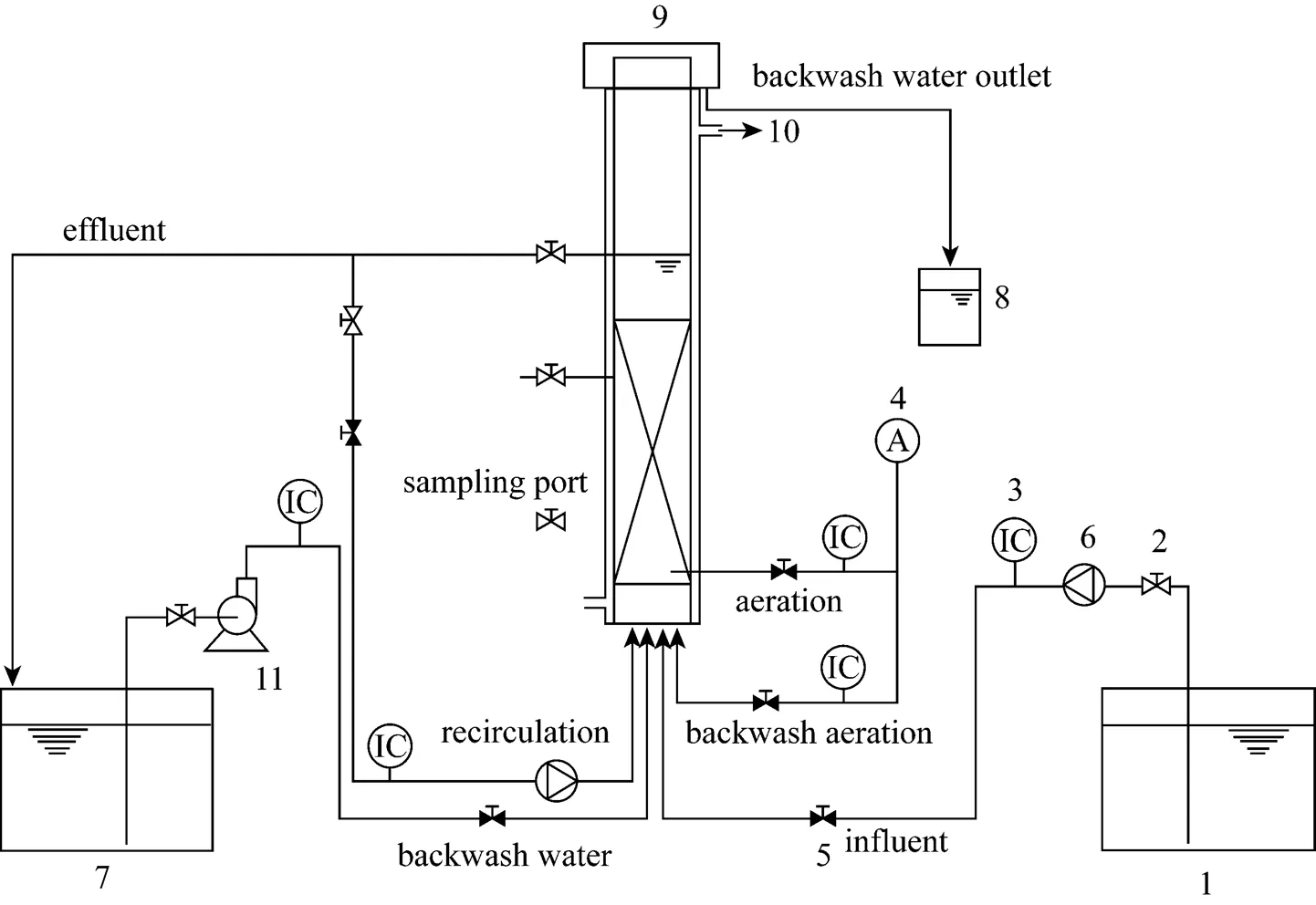
Figure 1 Experiment installation
1—feed tank; 2—manual valve; 3—rotameter or water flowmeter; 4—air compressor; 5—electrically operated valve; 6—peristaltic pump; 7—polishing tank; 8—storage tank; 9—biological aerated filter; 10—thermostatic bath; 11—pump

Table 1 The parameters of ceramic particles
2.2 Experimental system and conditions
The pilot-scale biological aerated filter system was a polymethyl methacrylate column with 0.15 m inner diameter and a length of 2 m, filled with 1.0 m of ceramic particles (Fig. 1). From the base of the reactor, 11 sampling ports were set and the distance between two ports was 0.1 m. The COD concentrations of each effluent sample taken from each sampling port were measured. In order to achieve the stable state conditions, the reactor was operated for 7 days under each operation condition. The porous ceramic particles were used as the medium for biofilm development. The parameters of the ceramics are listed in Table 1.
In this study, the air flow rate was 68.16 m3·m-2·d-1.The thermostatic bath was used to keep the cultivation temperature at 30°C. The BAF was operated without recirculation. During the operation period, head loss was monitored by measurement of water lamina height, which indicated the need for biofilter backwashing. In this process, the ceramic particles was loosened first by a flow of air (about 1920 m3·m-2·d-1) for 1 min, and then by a combined flow of water (about 960 m3·m-2·d-1) and air (about 960 m3·m-2·d-1) for 1 min. Finally, a flow of water (about 480 m3·m-2·d-1) was applied for 2 min to eliminate the remaining biomass. The reactor was initially inoculated with pure culture ofsp. NJUST16. The characteristics of the inocula and the start-up procedure of the BAF were described previously [12].
2.3 Theory
At steady state, the sorption of TNP on the packing material (adsorption on the solid and absorption in the water retained in the pores of solid) is in equilibriumand is not taken into consideration in the mass balances.
With the assumption of pseudo first-order kinetics and plug flow, the substrate removal rate can be described as follows [13]:


in which1is the reaction rate constant with VSS included [4].
Integrating Eq. (2) yields

whereand0are the contact time and the influent COD concentration, respectively.
The mean residence time of the fluid in the reactor,, is related to the filter depth, the hydraulic loading rate and the nature of the support [13]:
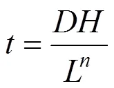
whereis the medium height,is the hydraulic loading rate,andare constants related to the medium and its specific surface.
Substitution of Eq. (4) into Eq. (3), leads to [4]
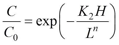
On the other hand, the mean residence timecan be related to the volumetric load of mediaw[3],
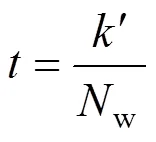
where′ is the biomass constant, which depends on the hydraulic characteristics of the reactor, andwcan be expressed as [3]:

whereis the volumetric flow rate, andis the cross-sectional area of the reactor.
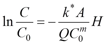
With Eqs. (6) and (7), Eq. (3) becomes [3]

Equation (8) may be written as [2]


2.4 Analytical methods
TNP concentration and COD were determined by the method described previously [11]. The pH was measured with a pH meter (PHS-3B, Shanghai Precision & Scientific Instrument Co. Ltd, China). After inoculation, biofilm formation in the BAF reactor was confirmed by scanning electron microscopy (SEM, JEOLJSM-6380LV, JEOL Ltd, Japan). Support materials were collected from the bottom of the column. The microorganisms were fixed with 4% glutaraldehyde and 1% osmic acid, and then dehydrated in an ethanol gradient. Subsequently, the specimens were dried in a critical drying apparatus (HCP-2, HITACHI, Japan) and given a metal coating with gold.
3 RESULTS AND DISCUSSION
3.1 BAF performance and biomass formation
The start-up process took about 3 weeks [12]. The reactor performance was checked by measuring TNP and COD concentrations. After operated for about 60 d, the TNP and COD were degraded in the BAF rapidly. At the bottom of the reactor, a thin biofilm covering the particles could be observed. The biofilm formation was confirmed by the SEM analysis (Fig. 2). The ceramic particles presented a rugged surface that is ideal for biofilm formation [Fig. 2 (a)]. The cell morphology and space arrangement are clearly visible [Fig. 2 (b)]. The result indicates that the support material is suitable.
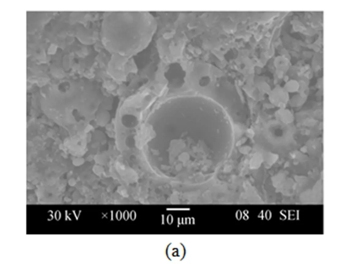
Figure 2 Scanning electron microscopy: (a) support material before inoculation; (b) support material with biofilm formed after inoculation
During the experimental period, the maximum apparent TNP volumetric removal rate was 2.53 kg·m-3·d-1, with the TNP removal rate of 98.7%. Accordingly, the maximum COD volumetric removal rate was as high as 2.3 kg·m-3·d-1(1 kg·m-3of TNP corresponded to 0.978 kg·m-3), with the removal rate of 93.0% [12], showing that the BAF reactor initially inoculated withsp. NJUST16 was highly efficient for removing organic material from wastewater containing high concentration of TNP. In addition, the maximum influent TNP concentration of 1.5 kg·m-3was rather high compared to the aerobic sequencing batch reactor [14] and the hollow-fiber membrane biofilm reactor [15].
3.2 Kinetic behavior as a function of influent COD concentration
The COD removal at different media height was investigated when the volumetric flow rate was controlled at 0.03 m3·d-1. COD concentrations () as a function of the column height () for various COD concentrations of influent are presented in Table 2. The largest increment of removal efficiency appears at the bottom of the reactor, where enough nutrition is provided for heterotrophic bacteria growth. For the influent COD concentration of 0.587, 0.783, 0.978, 1.174 and 1.369 kg·m-3, the effective height for COD removal is 0.4, 0.5, 0.6, 0.8 and 0.9 m, respectively. Above the effective height, the COD declines slowly, with about 0.04 kg·m-3residual COD, which is rather difficult to degrade.

Table 2 COD concentration (kg·m-3) as a function of thefilter height (H) for different influent CODconcentration (C0)


Figure 3 The relationship between ln(0/) and the reactor heightat different influent COD concentrations

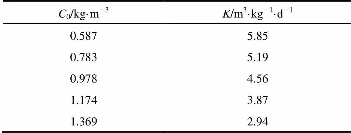
Table 3 Values of K as a function of influent CODconcentration (C0)

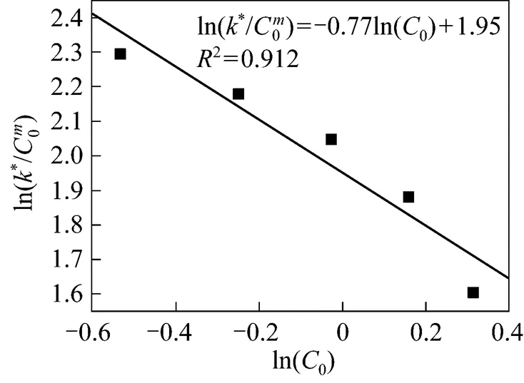


which may be used to predict the COD concentration and COD removal at different influent COD concentrations in the biological aerated filter.
3.3 Kinetic behavior as a function of hydraulic loading rate
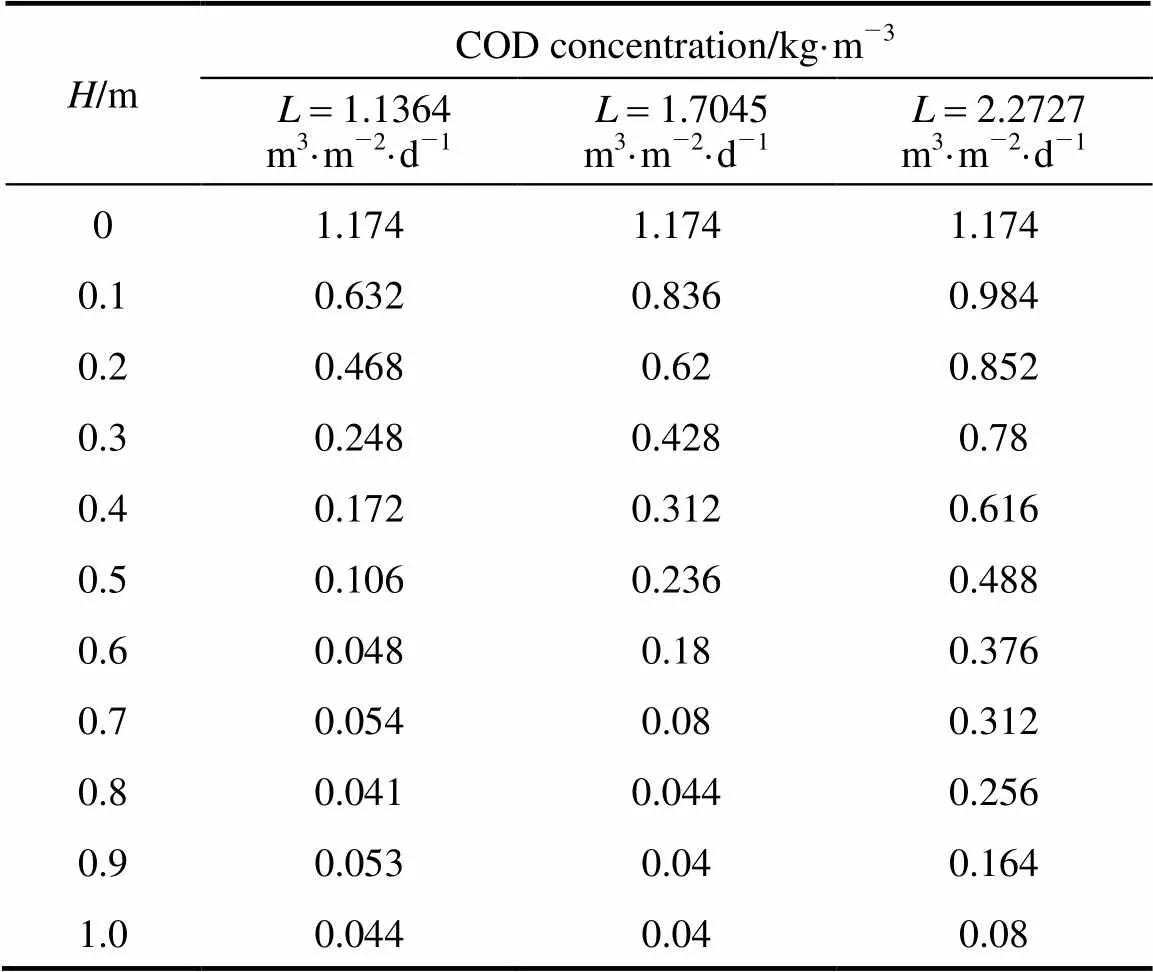
Table 4 presents the COD concentration (C) as a function of the column depth (H) at various hydraulic loading rate. The influent COD concentration was 1.174 kg·m-3 (corresponding to the influent TNP concentration of 1.2 kg·m-3). Higher values of inlet velocity decrease the residence time and thus inadequate for mass transfer. For example, at the hydraulic loading rate of 2.841 m3·m-2·d-1, the effluent TNP was relatively high. Therefore, the hydraulic loading rates studied were lower, as shown in Table 4.

Under these conditions, the effluent COD concentration is
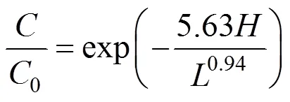
which may be used to predict the COD concentration and COD removal along the reactor height with different hydraulic loading rates in the biological aerated filter.
Figure 5 The relationship between ln (0/) and the reactor heightas a function of hydraulic loading rates


Table 5 Values of K2/Ln as a function of L

Figure 6 Linear regression for determination of model parameterand2
3.4 Simulations with the models
With the process parameters in the empirical Eqs. (5) and (9), Fig. 7 shows the COD profile along the reactor height. The removal of COD is in agreement with the experimental data at influent COD concentration of 1.174 kg·m-3, and the COD removal rate is only slightly different.
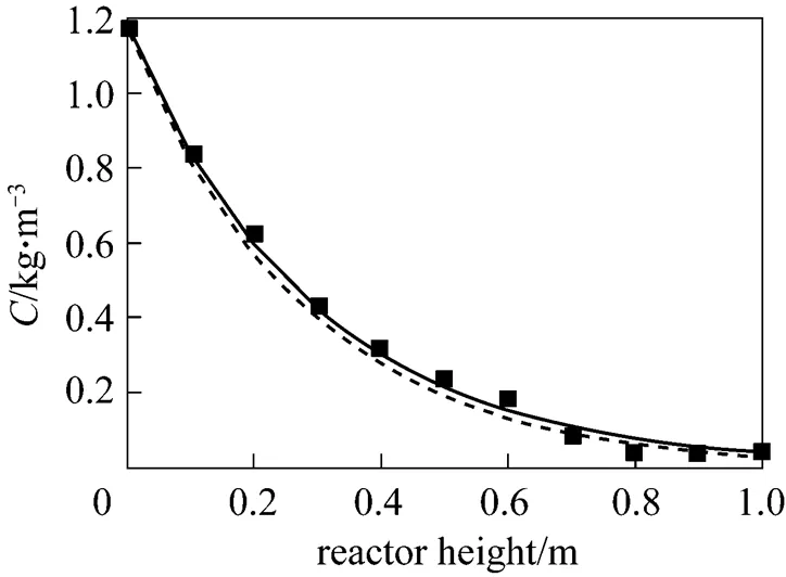
Figure 7 Comparison of predicted COD profiles along the reactor with experimental data


4 CONCLUSIONS

NOMENCLATURE
cross-sectional area of the reactor, m2
COD concentration, kg·m-3
0influent COD concentration, kg·m-3
medium height, m
rate constant, m3·kg-1·d-1
iHaldane’s growth kinetics inhibition coefficient, mg·L-1
shalf saturation coefficient, mg·L-1
1reaction rate constant with VSS included, d-1
′ biomass constant, kg·m-3

hydraulic loading rate, m3·m-2·d-1
wvolumetric load, kg·m-3·d-1
volumetric flow rate, m3·d-1
time, d
microbial biomass concentration expressed as volatile suspended solids, kg·m-3
maxmaximum specific growth rate, h-1
1 Allan, M., Leopoldo, M.E., Tom, S., “A comparison of floating and sunken media biological aerated filters for nitrification”,...., 72, 273-279 (1998).
2 Wang, C., Li, J., Wang, B., Zhang, G., “Development of an empirical model for domestic wastewater treatment by biological aerated filter”,., 41, 778-782 (2006).
3 Mann, A.T., Stephenson, T., “Modeling biological aerated filters for wastewater treatment”,., 31, 2443-2448 (1997).
4 Su, D., Wang, J., Liu, K., Zhou, D., “Kinetic performance of oil-field produced water treatment by biological aerated filter”,...., 15 (4), 591-594 (2007).
5 Heiss, G., Knackmuss, H.J., “Bioelimination of trinitroaromatic compounds: immobilizationmineralization”,..., 5, 282-287 (2002).
6 Hofmann, K.W., Knackmuss, H.J., Heiss, G., “Nitrite elimination and hydrolytic ring cleavage in 2,4,6-trinitrophenol (picric acid) degradation”,..., 70, 2854-2860 (2004).
7 Nga, D.P., Altenbuchner, J., Heiss, G.S., “NpdR, a repressor involved in 2,4,6-trinitrophenol degradation inHL PM-1”,.., 186, 98-103 (2004).
8 Ramos, J.L., González-Pérez, M.M., Caballero, A., van Dillewijn, P., “Bioremediation of polynitrated aromatic compounds: plants and microbes put up a fight”,..., 16, 275-281 (2005).
9 Rieger, P.G., Sinnwell, V., Preuβ, A., Francke, W., Knackmuss, H.J., “Hydride-Meisenheimer complex formation and protonation as key reactions of 2,4,6-trinitrophenol biodegradation byerythropolis”,.., 181, 1189-1195 (1999).
10 Rieger, P.G., Meier, H.M., Gerle, M., Vogt, U., Groth, T., Knackmuss, H.J., “Xenobiotics in the environment: present and future strategies to obviate the problem of biological persistence”,.., 94, 101-123 (2002).
11 Shen, J., Zhang, J., Zuo, Y., Wang, L., Sun, X., Li, J., Han, W., He, R., “Biodegradation of 2,4,6-trinitrophenol bysp. isolated from a picric acid-contaminated soil”,..., 163, 1199-1206 (2009).
12 Shen, J., He, R., Yu, H., Wang, L., Zhang, J., Sun, X., Li, J., Han, W., Xu, L., “Biodegradation of 2,4,6-trinitrophenol (picric acid) in a biological aerated filter (BAF)”,.., 100, 1922-1930 (2009).
13 Sá, C.S.A., Boaventura, R.A.R., “Biodegradation of phenol byDSM 548 in a trickling bed reactor”,..., 9, 211-219 (2001).
14 Weidhaas, J.L., Schroeder, E.D., Chang, D.P., “An aerobic sequencing batch reactor for 2,4,6-trinitrophenol (picric acid) biodegradation”,.., 97, 1408-1414 (2007).
15 Grimberg, S.J., Rury, M.J., Jimenez, K.M., Zander, A.K., “Trinitrophenol treatment in a hollow fiber membrane biofilm reactor”,..., 41, 235-238 (2000).
16 Shen, J., He, R., Wang, L., Zhang, J., Zuo, Y., Li, Y., Sun, X., Li, J., Han, W., “Biodegradation kinetics of picric acid bysp. NJUST16 in batch reactors”,..., 167, 193-198 (2009).
17 Anthonisen, A.C., Loehr, R.C., Prakasam, T., Srinarh, E.G., “Inhibition of nitrification by ammonia and nitrous acid”,...., 48 (5), 835-852 (1976).
18 Aslan, S., Dahab, M., “Nitritation and denitritation of ammonium-rich wastewater using fluidized-bed biofilm reactors”,..., 156, 56-63 (2008).
19 Glass, C., Silverstein, J., “Denitrification kinetics of high nitrate concentration water: pH effect on inhibition and nitrite accumulation”,., 32, 831-839 (1998).
20 Glass, C., Silverstein, J., “Denitrification of high-nitrate, high-salinity wastewater”,., 33, 223-229 (1999).
21 Weon, S.Y., Lee, C.W., Lee, S.I., Koopman, B., “Nitrite inhibition of aerobic growth ofsp”,., 36, 4471-4476 (2002).
22 Behrend, C., Heesche-Wanger, K., “Formation of hydride-Meisenheimer complexes of picric acid (2,4,6-trinitrophenol) and 2,4-dinitrophenol during mineralization of picric acid bysp. strain CB 22-2”,..., 65, 1372-1377 (1999).
2008-11-21,
2009-09-07.
Innovation Grant for Graduate of Jiangsu Province (AD20246).
** To whom correspondence should be addressed. E-mail: wanglj@mail.njust.edu.cn
杂志排行
Chinese Journal of Chemical Engineering的其它文章
- Effect of Working Temperature on the Resistance Characteristic of aPleated Stainless Steel Woven Filter*
- The Numerical Simulation of Collapse Pressure and Boundary of the Cavity Cloud in Venturi*
- Performance of Inner-core Supersonic Gas Separation Device with Droplet Enlargement Method*
- Void Fraction Distributions in Cold-gassed and Hot-sparged Three Phase Stirred Tanks with Multi-impeller*
- Representation of Phase Behavior of Ionic Liquids Using the Equation of State for Square-well Chain Fluids with Variable Range*
- Proton-exchange Sulfonated Poly(ether ether ketone)/SulfonatedPhenolphthalein Poly(ether sulfone) Blend Membranes in DMFCs*
