Performance of Inner-core Supersonic Gas Separation Device with Droplet Enlargement Method*
2009-05-15MAQingfen马庆芬HUDapeng胡大鹏HEGaohong贺高红HUShijun胡施俊LIUWenwei刘文伟XUQiaolian徐巧莲andWANGYuxin王予新
MA Qingfen (马庆芬), HU Dapeng (胡大鹏), HE Gaohong (贺高红), HU Shijun (胡施俊), LIU Wenwei (刘文伟), XU Qiaolian (徐巧莲) and WANG Yuxin (王予新)
Performance of Inner-core Supersonic Gas Separation Device with Droplet Enlargement Method*
MA Qingfen (马庆芬)1,2, HU Dapeng (胡大鹏)1,**, HE Gaohong (贺高红)3, HU Shijun (胡施俊)1, LIU Wenwei (刘文伟)4, XU Qiaolian (徐巧莲)1and WANG Yuxin (王予新)5
1Department of Chemical Machinery, Dalian University of Technology, Dalian 116012, China2Department of Mechanical Engineering, Hainan University, Haikou 570228, China3Department of Chemical Engineering, Dalian University of Technology, Dalian 116012, China4China Liaohe Petroleum Engineering Co., Ltd. (LPE), Panjin 124010, China5China Beijing Dwell Petroleum & Gas Technology Development Company Ltd., Beijing 100085, China

supersonic gas separation, gas mixture with a single heavy component, heterogeneous nucleation, cyclone gas/liquid separation
1 INTRODUCTION
Supersonic gas separation (SGS), a novel gas separation technology proposed in recent years [1-4], with similar thermodynamics to a turbo-expander, combines expansion, cyclone gas/liquid separation and re-compression in a compact static device. The device, with no rotating parts and operated without chemicals, ensures a simple and environmentally friendly facility, with a high reliability and availability, suitable for de-manned operation. To date, the reports on the experimental study for the technology are very limited and mainly focus on gas separation process of high-pressure natural gas flow (with inlet pressure more than 3.5MPa) from gas fields. Okimoto and Brouwer [5] designed an SGS device, Twister separator, and suggested that a maximum dew point depression of 22-28°C could be obtained, but the corresponding experimental conditions were not given. Then, the effectiveness of Twister separator was further studied experimentally [6, 7] and some factors influencing the separation effectiveness were found. Alfyorov. [8] designed an SGS device, 3-S separator, and tested it several times. Compared to Joule-Thomson valve and turboexpander, the 3-S separator could save 10%-20% compressor power for the same extraction level, and extract more C3+ from natural gas. Under certain conditions, especially with small concentrations of heavier hydrocarbons, the 3-S separator could separate liquid components that the Joule-Thomson valve could not separate.
Although it has been proved that SGS is effective for the high-pressure natural gas processing, when it is applied for processing low-pressure gas mixture (inlet pressure less than 1.0 MPa) containing a single heavy component, the separation performance is much worse. Liu. [9] designed an SGS device and conducted an indoor test for dehumidification of low-pressure moist air and only attained a maximum dew point depression of about 18°C with the pressure loss more than 70%. In this study, a novel structure of SGS device with shorter settlement distance is constructed and an effective method for improving the device performance, droplet enlargement method, is applied. Series of experiments are carried out to validate the novel structure and method, and effects of some important parameters including the inlet pressure, temperature and relative humidity, swirling intensity, and mass flow rater of water are investigated.
2 METHOD OF DROPLET ENLARGEMENT
2.1 Theoretical fundamental—homogenous and heterogeneous nucleation
If a gas mixture contains a single heavy component and no foreign particle exists, the appearance of the second phase (liquid) is governed by the process of homogeneous nucleation [10]. The free-energy barrier for the formation of very fine droplets can be overcome only when a high supersaturation condition is achieved. In this case, the critical nucleation radius given by the Kelvin equation [11] is very small, and the droplets formed are in size of 1 μm [12, 13]. As well known, it is difficult to separate the submicron droplets when they are smaller than 2.5 μm [14-18]. Therefore, to improve the separation performance of SGS device for the treatment of gas mixture with a single heavy component, the droplets should be enlarged.
When solid particles are initially present in a gas carrier phase with vapor, Wilson observed that condensation appeared at low saturation conditions: heterogeneous condensation can occur at saturation ratio a few percents greater than 1. Solid particles act as nucleation centers and the vapor molecules deposit on the particle surface because of the sticking forces. The liquid film formed on the particle has a large curvature radius (compared to homogeneous nucleation), promoting deposition of vapor molecules due to the Kelvin effect. Hinds defined two kinds of solid particles: soluble and insoluble nuclei [19]. Because an insoluble nucleus needs larger saturation ratio for condensational growth, a soluble nucleus may be chosen as a condensation nucleus under low saturation and even sub-saturation conditions [20-22].
2.2 Droplet enlargement—adding nucleation centers
Based on the homogeneous and heterogeneous nucleation theory, a droplet enlargement method of adding nucleation centers is proposed to improve the separation performance of SGS device. The selected nucleation centers should meet the following requirements.
(1) The supersaturation for activation of nucleation centers from added particles should be as small as possible, so that the condensation happens earlier, leading to larger size of droplets. Thus the nucleation centers should be soluble in the heavy component of gas mixture.
(2) The added nucleation centers should have good fluidity so as to be removed easily, avoiding the block of pipelines due to their local accumulation. Thus the selected nucleation centers should remain liquid state in the SGS device.
(3) The volatility of added nucleation centers should be much lower than that of the heavy component to avoid the pollution of the added liquid droplets in the gas phase.
(4) There is no chemical reaction between added nucleation centers and any component of gas mixture, to avoid the external pollution caused by the generation of new substance.
According to the above requirements, the nucleation centers added into the SGS device for the droplet enlargement should be the micro-droplets with lower volatility, soluble in heavy component and without reaction with any component of gas mixture. In this paper, gas mixture of air and ethanol vapor is chosen as the experimental medium and micro droplets of water are used as the nucleation centers.
3 EXPERIMENTAL APPARATUS AND PROCESS
3.1 Inner-core SGS device
Figure 1 shows the structure of the inner-core SGS device [23] proposed for this study. The device is composed of three key parts: swirling generator, supersonic nozzle (converging-diverging nozzle) and gas diffuser. Comparing with the traditional structure, the swirling generator and supersonic nozzle are improved to reduce the energy loss and improve the separation performance.
3.1.1
In the traditional structure, the rotation of the two phase flow is generated by a swirling ring set up in the downstream of the diverging nozzle. However, shock waves due to the collision of the swirling ring and high speed flow might increase the energy loss and even destroy the low-pressure and -temperature environment which is necessary for the condensation of heavy component. To overcome this disadvantage, a novel structure of swirling generator is designed. As shown in Fig. 1, the swirling generator is in front of the converging-diverging nozzle. It is composed of several arc blades tangent to the nozzle and the spaces between adjacent blades form flow channels for the gas mixture. When the gas flow passes through these channels, it is accelerated and finally enters the nozzle with the tangential velocity of a certain value. Its axial velocity is much less than the sound velocity since the nozzle cross-section is much bigger than that of the nozzle throat. Thus, shock waves caused by the swirling generator are completely eliminated.
The magnitude of the inlet tangential velocity can be controlled by inlet pressureinand the area of the minimum section of the channelsmin. Increasinginor decreasingminincreases the inlet tangential velocity.minis determined by the height of the swirling generator, the minimum distance between two bladesand the blade numberb.
3.1.2


Figure 1 Schematic graph of constructed SGS device

3.2 Experimental process
An experimental process and a measurement system are set up to investigate the separation performance of the improved SGS technique. A schematic diagram of experimental process and apparatus is shown in Fig. 2. The high pressure air is supplied by a gas supply system, which is composed of a four-stage compressor with the maximum pressure of 20 MPa and a storage tank of 10 m3. Ethanol vapor is produced from 95% ethanol liquid by a water vapor heater of 10 kW and then mixed with the air flow generated in the mixer & heater. The gas mixture with certain temperature enters the SGS device and the ethanol condenses on micro water droplets generated by an atomizer located around the throat of the supersonic nozzle. The liquid film on the nozzle wall is discharged together with a small portion of gas from the wet outlet. The dry gas goes out of the SGS device after it passes through a diffuser, which is used for the pressure recovery, and then vents into the atmosphere (the back pressure of outletbis 0.1 MPa).
For the limitation of device space, a deep small hole with diameter of 0.22 mm and depth of 10 mm is chosen as the atomizer to avoid the damage to the gas flow field around the throat of SGS device. The water injected from the small hole encounters the self-rotational supersonic gas flow around the throat of SGS device and then breaks up into a great many micro droplets. For the above complex flow state, the size of added water droplets can be hardly measured. However, it is sure that the added water droplets can decrease the supersaturation degree for the activation of condensation [20-22] and enlarge the size of final droplets from condensation [11], which is helpful for the improvement of SGS device performance.
3.3 Measurement system
The system consists of instruments measuring the flow rate, pressure, temperature and content.
3.3.1
(1) Flow rate of gas mixture
The mass flow rates of the gas mixture are investigated by those of inlet and wet outlet. Because the mass flow rate of ethanol in the gas mixture is really small compared to that of air, the inlet mass flow rate of gas mixture can be considered as that of air flow, which is obtained by an orifice meter in the upper steam of device with the minimum diameter of 9 mm. The mass flow rate of the wet outlet is calculated from the volume flow rate measured by a suspended body flowmeter with a range of 50-300 m3·h-1.
(2) Flow rate of liquid ethanol and water
Since ethanol vapor in the gas mixture is produced by the evaporation of ethanol liquid, the flow rate of ethanol liquid should be controlled to ensure that the added ethanol liquid is completely evaporated by the heater. This flow rate is measured by a suspended body flowmeter with a range of 6-60 L·h-1.
In this paper, micro water droplets are added into the SGS device to promote the condensation of ethanol vapor and enlarge the size of condensed droplets, for improving the separation performance of SGS device. The quantity of added water droplets represented by volume flow rate may affect the separation performance, which will be discussed in the following part. This volume flow rate is measured with a suspended body flowmeter with a range of 10-100 ml·min-1.
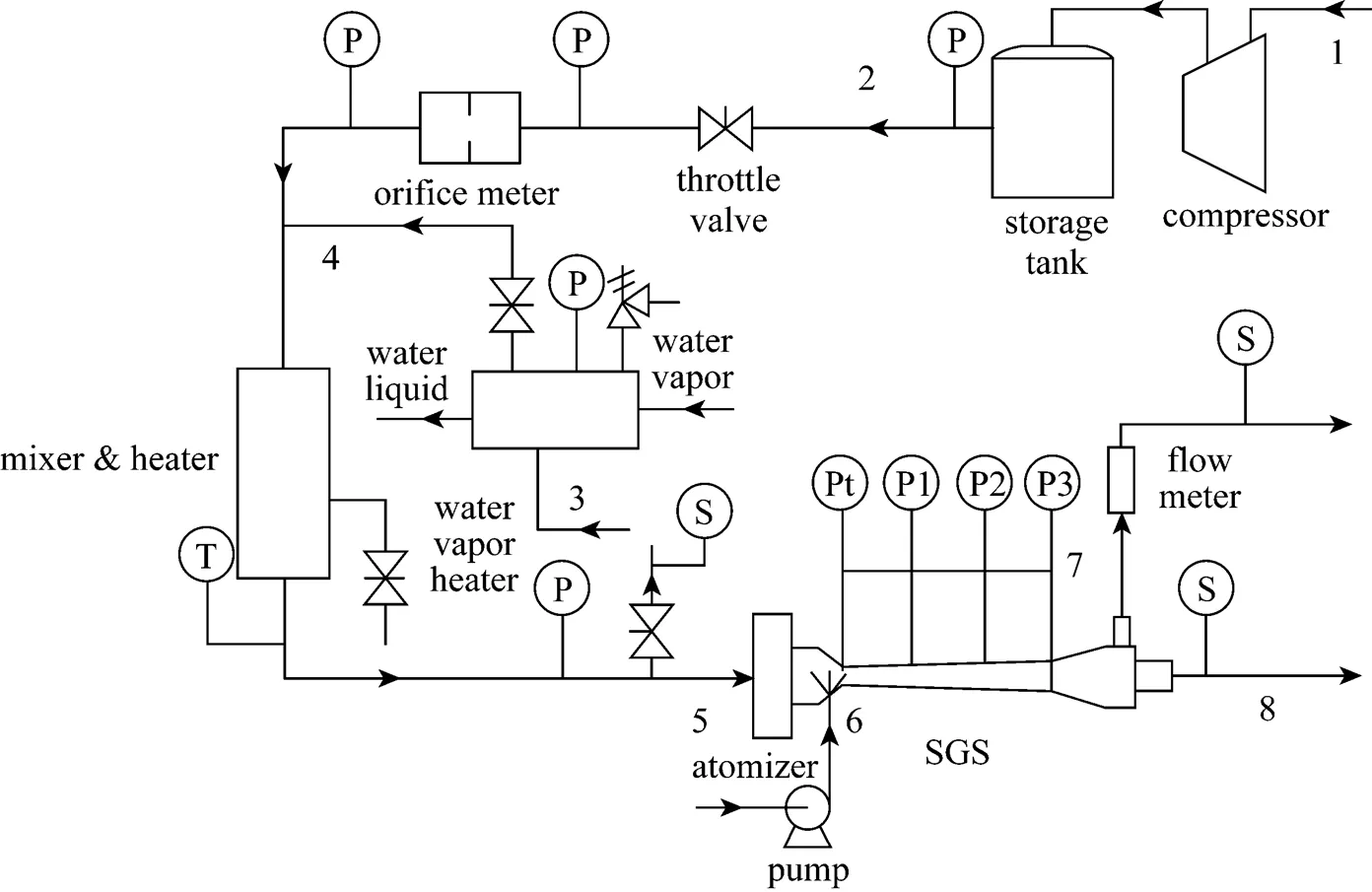
Figure 2 Schematic diagram of the experimental process and apparatus
1—low pressure air; 2—high pressure air; 3—ethanol liquid; 4—ethanol vapor; 5—mixture of air and ethanol vapor; 6—micro droplets of water; 7—wet outlet flow; 8—dry outlet flow
3.3.2

3.3.3
To determine the content of each component of gas mixture from the inlet and two outlets of SGS device, sampling ports are set at these positions. During the experimental process, after the operating conditions become stable, gas samples are taken and then gas component and content are determined by gas chromatographyanalysis (Agilent 6890N Series Gas Chromatograph). The chromatographic column and detector employ FFAP capillary column 30 m×0.53 mm×1.0 μm and TCD detector, respectively. Fig. 3 shows an arbitrary chromatogram of each component obtained in the experiment. The retention time of air, ethanol and water on the chromatographic column are 1.512, 2.211 and 3.011 min, respectively. The resolutions of all chromatographic peaks are more than 1, indicating that every component can be effectively separated. Based on the area of chromatographic peak, the mole fraction of each component is obtained using external standard method.
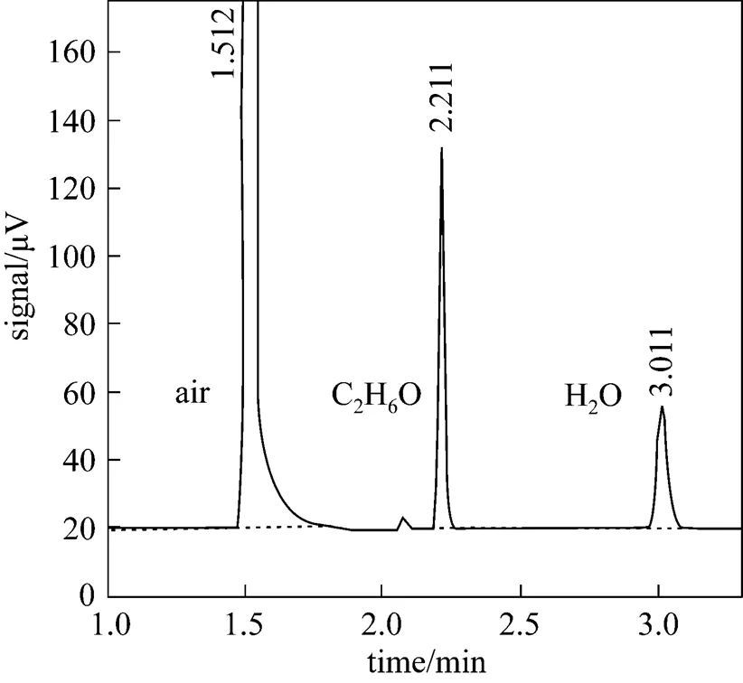
Figure 3 Chromatogram of each component in gas mixture
3.4 Evaluation indexes of performance
In order to investigate the separation performance of the designed structure and proposed method, experiments are carried out under various conditions. As the technology is for separating the heavy component (ethanol) from the gas mixture (mixture of air and ethanol vapor), the removal efficiency of heavy component is the most important index for the evaluation of separation performance. Since extra substance such as water is added and may pollute the basic flow system, the pollution extent should also be evaluated.


Table 1 Comparison of ethanol saturation pressurebetween calculation results of Antoine equation andexperimental data

Another important index may be used to evaluate the processing capacity of SGS device,.., the recovery rate of dry outlet gas, which is defined as

wherein,dryandwetrepresent the mass flow rate of SGS device at inlet, dry outlet and wet outlet, respectively.
4 RESULTS AND DISCUSSION
4.1 Static pressure profile
To obtain the low-pressure and -temperature environment for the condensation of heavy component, the gas flow should be maintained in the supersonic state in the diverging part of supersonic nozzle. In this study, the flow state is investigated by the static pressure measurement.

Table 2 Measurement results of the static pressure profile and mass flow rate
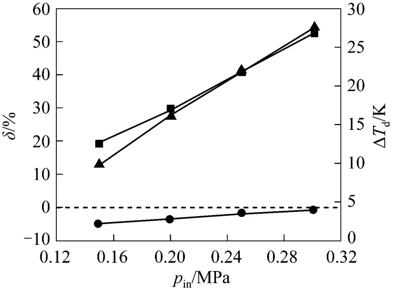


According to the energy balance law and structure of inner-core SGS device, highercauses weaker swirling intensity of gas flow, leading to less energy loss, and higherinsupplies more inlet energy. Thus the increase inandinsupplies more energy available to maintain high speed flow in the diverging nozzle, so that the required supersonic flow field can be obtained.
4.2 Recovery rate
Table 2 also shows the mass flow rate of SGS device at the inlet and wet outlet (inandwet). The recovery rate of dry outlet gasis calculated using Eq. (4). In the present SGS device,can be maintained above 80%, so that more than 80% of the inlet gas can be effectively treated.
4.3 Separation performance
Effects of some important parameters on the separation performance of SGS device with the droplet enlargement method will be discussed in this section, including inlet pressurein, inlet temperaturein, inlet relative saturation of ethanolin, volume flow rate of added waterw, and swirling intensity. The definition of the inlet relative saturation of ethanolinis defined as

4.3.1in

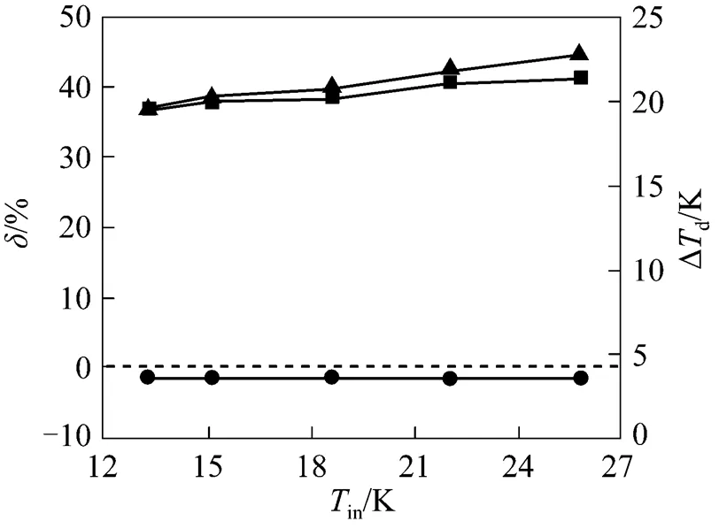


4.3.2in


4.3.3in

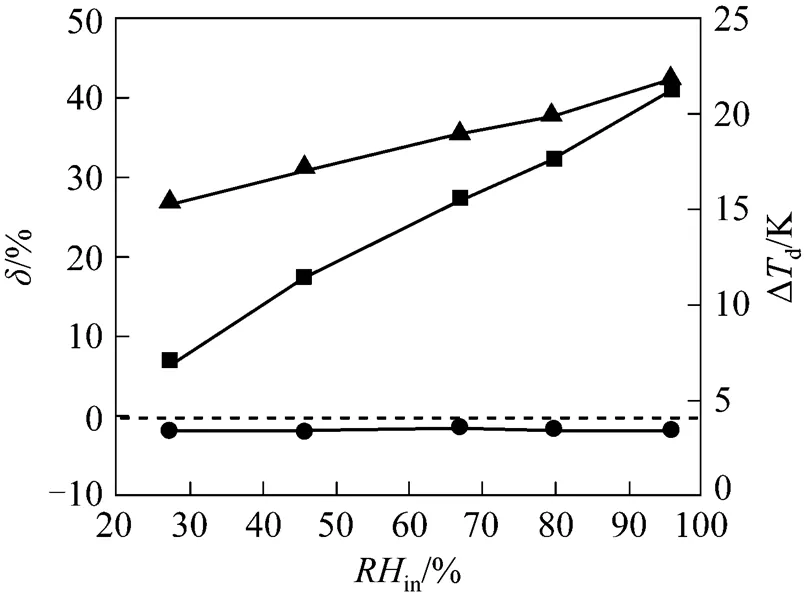


4.3.4

4.3.5w

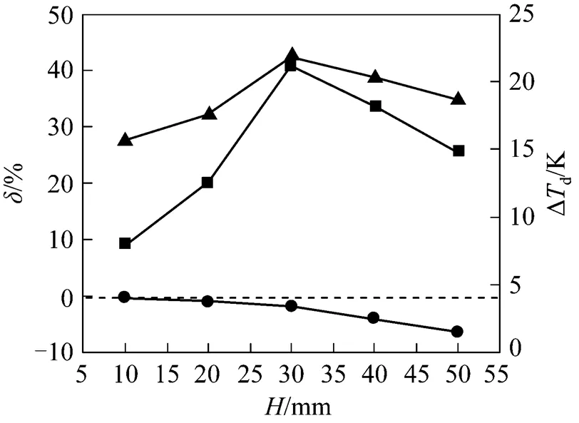


5 CONCLUSIONS

NOMENCLATURE
carea of nozzle throat, mm2
minimum distance between two blades of swirling generator, mm
height of swirling generator, mm
length of diverging nozzle, mm
bblade number of swirling generator
ininlet pressure, MPa
tpressure of nozzle throat, MPa
1,2,3pressure values along the flow direction on the wall of diverging nozzle, MPa
inmass flow rate of gas mixture at inlet, kg·h-1
wetmass flow rate of wet outlet flow, kg·h-1
wmass flow rate of added water, kg·h-1
relative humidity with similar definition for moist gas, %
ccritical radius of nucleus, mm
saturation ratio
static temperature, K
ddew point, K
gtemperature of gas phase, K
ininlet temperature of SGS device, K
0stagnation temperature, K
Δddew point depression between inlet and dry outlet, K
mole fraction, %
residual gas rate, %
ρliquid density, kg·m-3
surface tension, N·m-1
Superscripts
in inlet of SGS device
dry dry outlet of SGS device
wet wet outlet of SGS device
Subscripts
C2ethanol
H2O water
in inlet of SGS device
1 Betting, M., “Nozzle for supersonic gas flow and an inertial separator”, US Pat., 6513345 B1 (2003).
2 Brouwer, J.M., Epsom, H.D., Twister, B.V., “Twister supersonic gas conditioning for unmanned platforms and subsea gas processing”, In: Offshore Europe, Society of Petroleum Engineers Inc., United Kingdom (2003).
3 Cao, X.W., Chen, L., Lin, Z.H., Du, Y.J., “Supersonic swirling separators”,, 27 (7), 1-3 (2008). (in Chinese)
4 Tu, H., Jiang, H., Liu, X.Q., “Application of supersonic separator to natural gas dehydration”,.., (3), 109-111 (2007). (in Chinese)
5 Okimoto, F., Brouwer, J.M., “Supersonic gas conditioning”,, 223 (8), 1170-1178 (2002).
6 Betting, M., Epsom, H., “Supersonic separator gains market acceptance”,, 228 (4), 197-200 (2007).
7 Schinkelshoek, P., Epsom, H.D., “Supersonic gas conditioning—commercialization of TwisterTMtechnology”, In: 5th GPA Annual Coference, Texas (2008).
8 Alfyorov, V., Bagirov, L., Dmitriev, L., Feygin, V., Imayev, S., Lacey, J.R., “Supersonic nozzle efficiently separates natural gas components”,, 103 (20), 53-58 (2005).
9 Liu, H.W., Liu, Z.L., Feng, Y.X., Gu, K.Y., Yan, T.M., “Characteristics of a supersonic swirling dehydration system of natural gas”,...., 13 (1), 9-12 (2005).
10 Oxtoby, D.W., “Homogeneous nucleation: theory and experiment”,..:., 4, 7627-7650 (1992).
11 Gerber, A.G., “Two-phase Eulerian/Lagrangian model for nucleating steam flow”,..., 124, 465-475 (2002).
12 Harstad, K., Bellan, J., “Modeling of multicomponent homogeneous nucleation using continuous thermodynamics”,, 139, 252-262 (2004).
13 Ma, Q.F., Hu, D.P., Qiu, Z.H., “Analysis of influence parameter on spontaneous nucleation during supersonic condensing separation”,, 37 (9), 920-925 (2008). (in Chinese)
14 Heidenreich, S., Vogt, U., Bittner, H., “A novel process to separate submicron particles from gases—A cascade of packed columns”,..., 55 (15), 2895-2905 (2000).
15 Bologa, A., Paur, H.R., Wäscher, T., “Electrostatic charging of aerosol as a mechanism of gas cleaning from submicron particles”,, 38 (10), 26-30 (2001).
16 Mansur, E.A., Wang, Y.D., Dai, Y.Y., “Separation of fine particles by using colloidal gas aphrons”,...., 12 (2), 286-289 (2004).
17 Huang, C.H., Tsai, C., Wang, Y.M., “Control efficiency of submicron particles by an efficient venture scrubber system”,..., 133 (4), 454-461 (2007).
18 Yan, J.P., Yang, L.J., Zhang, X., Sun, L.J., Zhang, Y., Shen, X.L., “Separation of PM2.5from combustion based on vapor condensation and scrubbing”,.., 36 (3), 267-272 (2008).
19 Hinds, W.C., Aerosol Technology: Properties, Behavior, and Measurement of Airborne Particles, John Wiley & Sons, New York (1982).
20 Gorbunov, B., Hamilton, R., “Water nucleation on aerosol particles containing both soluble and insoluble substances”,.., 28, 239-248 (1997).
21 Petersen, D., Ortner, R., Vrtala, A., Wagner, P.E., “Soluble-insoluble transition in binary heterogeneous nucleation”,..., 87 (22), 225703 (2001).
22 Jurski, K., Géhin, E., “Heterogeneous condensation process in an air water vapour expansion through a nozzle-experimental aspect”,.., 29, 1137-1152 (2003).
23 Hu, D.P., Dai, Y.Q., Zou, J.P., Zhu, C., Ma, Q.F., Qiu, Z.H., “Inner-conesupersonic gas separator”, CN Pat., 200820012508.3 (2008). (in Chinese)
24 Cheng, N.L., Handbook of Solvents, Chemical Industry Press, Beijing (2002). (in Chinese)
25 Wu, Z.N., Gas Dynamics, Tsinghua University Press, Beijing (2008). (in Chinese)
2008-11-17,
2009-08-18.
the Natural Science Foundation of Liaoning Province, China (20052193) and Ph.D. Programs Foundation of Ministry of Education of China (20070141045).
** To whom correspondence should be addressed. E-mail: hdphxp@163.com
猜你喜欢
杂志排行
Chinese Journal of Chemical Engineering的其它文章
- Effect of Working Temperature on the Resistance Characteristic of aPleated Stainless Steel Woven Filter*
- The Numerical Simulation of Collapse Pressure and Boundary of the Cavity Cloud in Venturi*
- Void Fraction Distributions in Cold-gassed and Hot-sparged Three Phase Stirred Tanks with Multi-impeller*
- Kinetics of COD Removal in a Biological Aerated Filter in thePresence of 2,4,6-Trinitrophenol (Picric Acid)*
- Representation of Phase Behavior of Ionic Liquids Using the Equation of State for Square-well Chain Fluids with Variable Range*
- Proton-exchange Sulfonated Poly(ether ether ketone)/SulfonatedPhenolphthalein Poly(ether sulfone) Blend Membranes in DMFCs*
