Effect of aspect ratio of elliptical stirred vessel on mixing time and flow field characteristics in the absence of baffles
2024-04-22YuanYaoPeiqiaoLiuQianZhangZequanLiBenjunXiChangyuanTaoYundongWangZuohuaLiu
Yuan Yao,Peiqiao Liu,Qian Zhang,Zequan Li,Benjun Xi,Changyuan Tao,Yundong Wang,Zuohua Liu,*
1 School of Chemistry and Chemical Engineering,Chongqing University,Chongqing 400044,China
2 Hubei Three Gorges Laboratory,Yichang 443007,China
3 Department of Chemical Engineering,Tsinghua University,Beijing 100084,China
Keywords: Mixing time CFD Stirred tank Secondary flow Mixing performance
ABSTRACT Elliptical tanks were used as an alternative to circular tanks in order to improve mixing efficiency and reduce mixing time in unbaffled stirred tanks(USTs).Five different aspect ratios of elliptical vessels were designed to compare their mixing time and flow field.Computational fluid dynamics (CFD) simulations were performed using the k–ε model to calculate the mixing time and simulate turbulent flow field features,such as streamline shape,velocity distribution,vortex core region distribution,and turbulent kinetic energy (TKE) transfer.Visualization was also carried out to track the tinctorial evolution of the liquid phase.Results reveal that elliptical stirred tanks can significantly improve mixing performance in USTs.Specifically,the mixing time at an aspect ratio of 2.00 is only 45.3%of the one of a circular stirred tank.Furthermore,the secondary flow is strengthened and the vortex core region increases with the increase of aspect ratio.The axial velocity is more sensitive to the aspect ratio than the circumferential and radial velocity.Additionally,the TKE transfer in elliptical vessels is altered.These findings suggest that elliptical vessels offer a promising alternative to circular vessels for enhancing mixing performance in USTs.
1.Introduction
The circular unbaffled stirred tank (C-UST) is a common used stirred equipment that has various applications,such as preventing cell damage during fermentation,reducing grain wear during crystallization,eliminating dead zone in high viscosity fluid mixing,and reducing energy consumption during solid–liquid suspension[1–7].However,in the C-UST,the formation of a central vortex leads to highly circumferential fluid motion,with minimal movement in the radial and axial directions[8].Consequently,the axial and radial mixing in the stirred tank without baffles remains insufficient even under large Reynolds numbers.Additionally,the mixing time in the C-UST is typically longer than in baffled tanks,leading to lower mixing efficiency [9].These limitations arise because the C-UST has an arbitrary profile symmetry,which tends to produce symmetry and periodic flow fields.To address these limitations,researchers have explored to break the symmetry and periodicity of flow field,investigating issues related spatial symmetry and time stability.
In terms of temporal behavior,it is noteworthy that the stirring speed changes over time instead of maintaining a constant speed.However,the changing function of the variation is crucial to improve the mixing efficiency.Recent studies have indicated that the chaotic wave function exhibits superior performance in enhancing the mixing effect when compared to sine wave,sawtooth wave,and forward and backward mode [10].Additionally,a comparison of two experimental conditions,namely chaotic speed and constant speed,has suggested that the chaotic speed can effectively increase the mixing performance [11].These findings underscore the significance of the time-varying function of stirring speed in achieving optimal mixing efficiency.
To improve the mixing performance in C-USTs,various approaches have been investigated,including spatial structure change and eccentric stirring systems.Baffles are commonly added to break the symmetry in space,which improves mixing performance[12].Although the core of this topic is to discuss the unbaffled stirred tank,the way of adding baffles can also be summarized as the spatial structure change.Moreover,eccentric stirring system have been widely studied to enhance the mixing performance.Clear findings confirmed that an eccentric stirring system can enhance both laminar and turbulent mixing performance,and the optimal eccentricity was found to be 0.42 [13,14].Karczet al.[15] investigated the mixing time in an eccentric stirred system and found that it can shorten the mixing time by about 50%,while the mathematical model for connection between mixing time and eccentricity indicated that eccentricity directly affects the mixing time.Montanteet al.[16] used a combination of particle image velocimetry(PIV)experiment and numerical simulation to investigate the turbulence characteristics of eccentric stirred system in a C-UST and found that eccentric stirred system can increase axial and radial velocity while destroying the symmetrical double-ring flow field structure.Galletti and Brunazzi [17] used laser Doppler anemometry(LDA)to study the eddy current in an eccentric stirred tank without baffles and found that eccentric system can enhance turbulence through increase macroscopic instability.Woziwodzkiet al.[18] investigated the effect of different agitators on mixing time in an eccentric stirred tank without baffles,calculated the quantitative relationship between mixing time and eccentricity.More findings can be found in the studies by Huanget al.[19],and Yamamotoet al.[5].Both researchers established the mechanism of intensification by increasing the macroscopic instability in the eccentric system.It is demonstrated that the eccentric stirred system has a compensation effect on the surface free vortex,which can effectively weaken the formation of the central vortex.However,the eccentric stirred system can cause macromechanical imbalance due to an axial force that force the impeller to return to the centerline,which disrupts the equipment’s stability for an extended period.
Many studies have been conducted to improve the chaotic mixing in stirred vessels.One effective means to destroy the periodic flow field is by using local asymmetric impellers.Several experiments and simulations of stirred tanks with asymmetric impellers have been conducted in the past decades.Bulnes-Abundis and Alvarez [20] provided a method to enhance the chaotic mixing for laminar mixing in an agitated tank by using an eccentrically located angled disc.Previous studies comparing fractal blades and non-fractal blade have found that fractal blades improve chaotic mixing in stirred tanks [21–23].Luanet al.[24,25] developed a staggered impeller with upper and lower blades to improve the mixing of non-Newtonian fluids and produced good results.Our research group has proposed rigid-flexible combined blades,which are made by pasting a section of flexible material at the tip of the blade,such as polytetrafluoro,polyvinyl chloride as well as spring.Rigid-flexible combined blades can increase the chaotic mixing of fluid [26,27].Meanwhile,Lianget al.[28] created an elastic blade with the nickel alloy.They studied flow field structure and turbulence characteristics using PIV method,and compared elastic blades with six curved blades and six straight blades.The main contribution of the nickel alloy elastic blade to turbulence is enhancing the turbulent dissipation rate.The analysis above shows that research on the influence of blades structure on mixing performance has been widely reported.However,few researchers have studied the relationship between the shape of tank and mixing performance.
The shape of stirred vessels is typically round,although some non-round shapes have been studied.The influence of vessel shape is generally attributed to the influence factors of geometric structure.Consequently,the effect of tank shape on mixing performance has received little consideration.
In this present work,we changed the aspect ratio of crosssection of stirred tank to create a series of elliptical stirred vessels with the same base area.We combined experimental research with numerical simulation to study the mixing time,flow field structure evolution,velocity,and turbulent kinetic energy(TKE)distribution in a series of elliptical stirred tanks.These findings showed that elliptical stirred tanks (radial variable diameter) can effectively break the symmetry and periodic structure for the turbulent flow field,restrain the central vortex,shorten the mixing time,and appear chaotic mixing.To address the shortcoming of unbaffled stirred tanks,we proposed a new solution that can broaden the application of stirred tanks without baffles.
2.Methodology
2.1.Geometry model
Computational fluid dynamics (CFD) simulations were carried out in a series of elliptical tanks with varying aspect ratios that were filled with tap water and equipped with a Rushton disc turbine(RDT) impeller,as shown in Fig.1.The geometric dimensions corresponding to the values marked in Fig.1 are presented in Table 1.To make it clear,a plane Cartesian coordinate system was established,as shown by the red solid line in Fig.1.Based on the Cartesian coordinate system,the coordinates of the five pointsP1,P2,P3,P4,andPinwere presented in Table 2.

Table 1 Specific values of geometric dimensions

Table 2 Coordinates of the five points P1, P2, P3, P4,and Pin

Fig.1.Model geometry for CFD simulations.
As shown in Eq.(1),a new variableeis defined as the aspect ratio of the horizontal cross-section of stirred vessels,which describes the deviation between elliptical vessels and the cylindrical vessel.It is clear to understand thateequal to 1 represent a cylindrical vessel,andecan be commonly considered as a multiple of the long diameter compared to the short diameter.
where theTmaxis the long diameter,andTminis the short diameter of the ellipse cross-section.Five values ofeare 1.00,1.25,1.50,1.75 and 2.00,respectively.Later,theS(area of the tank bottom) andH(height of liquid level) are kept constant as shown in Eqs.(2) and(3).Based on the constant area of vessels and the height of liquid level,the dimensions of the semi-long diameter and semi-short diameter were calculated as shown in Table 3.

Table 3 The dimensions of semi-major axis and semi-minor axis
2.2.CFD simulation
In the simulation,the ANSYS Fluent 2021R1 commercial software was adopted and carried out using the finite volume method.Steady-and transient-state simulations were performed to calculate the mixing time as well as flow field characteristics.
The continuity equation with an unsteady term as shown in Eq.(4):
where ρ stands for the density of liquid,kg∙m-3;tis the flow time,s;vis velocity,m∙s-1.
The following (Eq.(5)) Navier–Stokes equation was adopted in single-phase simulation:
wheregstands for the gravity acceleration,in m∙s-2;prefers to pressure,in Pa.Fσis the surface tension term.
The liquid is tap water (ρ is 997.07 kg∙m-3,μ is 0.89 × 10⁻³Pa∙s).The agitating speed was set as 300 r∙min-1.Also the value of Reynolds numbers (Re) was calculated using the Eq.(6):
whereNis the agitation speed,r–1;μ is dynamic viscosity,Pa∙s.
In the simulation process for calculation flow field characteristics,we failed to consider the deformation of the free surface in the UST,while using a single-phase model to simulate flow field characteristics.The method of multiple reference frame (MRF) was used to treat the impeller rotating.Thek–ε model was employed as the turbulent model [1].Although this approach may result in the loss of some information near the free surface,its accuracy in describing the flow field within the UST is sufficient to meet the requirements,and it can significantly reduce the computational time.
To determine the mixing time in five stirred tanks,the concentration of the tracer,as a passive scalar φ,at different locations(described in Fig.1)were calculated using the tracer concentration monitoring method.In the simulation process,an Eulerian multiphase flow approach was employed to model the variation of the tracer solution with time.For the tracer simulations,the φ,a scalar concentration in the whole tank,was initialized to zero.And then,the φ at the feed point was set to 1 by the patch operation.The φ satisfies the transport Eq.(7).
where,σφis the turbulent Schmidt number andDφis the kinematic diffusivity of the scalar.
These data,obtained from Fluent,were dimensionless by Eq.(8).
where,C0is the initial concentration of the tracer in the vessel;C∞is the final concentration of the tracer;Ctis the concentration of the tracer at timet.
The next step was to plot the variation curve of dimensionless concentration with time,which gradually increased from zero to one.An appropriate criterion needs to be chosen to determine the endpoint of the mixing process.At present,±5%,that isCtis greater than 95% and less than 105%,has been selected as the criterion by most researchers [29–31].Although ±10% and ±1% have been selected as the criterion by some literature[32],the variation trends of the data obtained under different criteria are parallel and consistent qualitatively.Therefore,the criterion of±5% was chosen to calculate the mixing time.
The Cartesian coordinate center is located at the geometric center of the impeller.The boundary conditions were set such that the coincident surfaces between the static domain and the dynamic domain was set as the "interface".The sidewall and down surface were set as the "wall",while the upper surface was set as a "symmetry"boundary.The surfaces of impeller and shaft are set as antislip wall boundaries.In terms of solution methods,we adopted a second-order upwind scheme was adopted for discretization,and used the SIMPLE method for pressure–velocity coupling.The residual was set to 1 × 10⁻⁵.
The mesh sensitivity test was evaluated by monitoring the velocity values in the calculation domain.Velocity distributions under three grid values are shown in Fig.2.We adopted these values in respective computational grids as follows: 0.8 × 106,1.5×106,and 3.0×10⁶.It can be observed that the velocity distribution for different vessels at 1.5×10⁶mesh is almost the same as at 3.0 × 10⁶(difference below 2%).Considering the computational time and calculation accuracy,we adopt the number of cells for five shape vessels in Table 4.

Table 4 The mesh numbers in simulation for five stirred tanks
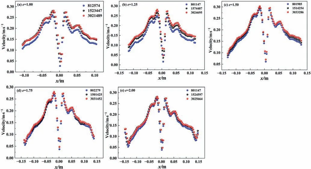
Fig.2.Velocity distribution under different mesh numbers for five shape stirred vessels: (a) e=1.00,(b) e=1.25,(c) e=1.50,(d) e=1.75,(e) e=2.00.
The numerical model applicability study was conducted by comparing the torque values of simulation and experiment.Fig.3 shows the relationship between the rotation speed and torque ate=1.00,1.25,1.50,1.75,2.00.The aim is to compare the difference between mean values of experiment and simulation.By comparing two values in Fig.3,it can be deduced that simulated values fit well with those form experiment.Therefore,this indicates that the selected model and parameter set can accurately simulate the target process.
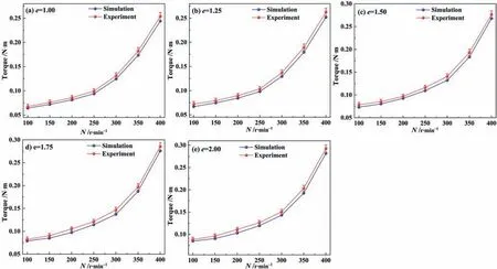
Fig.3.Model verification by comparing the torque value of experiment and numerical simulation under different agitation speed.
2.3.Experimental methods
To verify simulation results of mixing time,an experimental measure was performed using the method of acid-base neutralization achromatic based on the visualization of flow field [26].A high-speed camera (Revealer 5F04M) was adopted for visualization.Moreover,the torque measuring apparatus made by HuaXin Company with the model of HX-90D is located in the upper part of the shaft and close to the motor.The sampling frequency of the torque transducer is 1000 times per second.To reduce experimental error,the average of three experimental results was treated as the final value,and the uncertainty of the experimental data is less than 7%.
3.Results and Discussion
3.1.Effect of e on mixing time
A serious limitation of a C-UST is the long mixing time,which is not only related to the cost but also affects the quality of the pro-duct that their residence time is required accurately.In this section,the dependence of the mixing time on the degree of ellipse(e=1.00,1.25,1.50,1.75,and 2.00) was investigated.Numerical simulations shown in Fig.4 suggest that mixing time is 10.70,9.77,8.57,7.13,and 4.58 s forevalues of 1.00,1.25,1.50,1.75,and 2.00,respectively.This indicates that mixing time decreases aseincrease from 1.00 to 2.00.However,the decreasing range in mixing time is reduced aseincrease within the selected range.The minimum mixing time is only 45.3%of the maximum,in other word,mixing time in the E-UST (e=2.00) is about half that of the C-UST (e=1.00).This gives an estimate of the mixing time of the variable-radius vessel.
The non-constant distance between the sidewall and central axis leads to a radical change in main flow and results in breaking up of the flow field periodic structure;this is the same mechanism as the eccentric installation of the mixing shaft to shorten the mixing time.It should be note that increasingeto greater than 2.00 may not be significant for further exploration due to taking into account the turbulence intensity of farthest zone as well as the ratio of blade to tank diameter.
It seems like an experiment that compares the performance of three different stirred configurations: elliptical stirred tank(e=2.00),circular stirred tank with a central shaft,and circular stirred tank with an eccentric shaft (the ratio of the distance from the shaft to the central axis of tank is 0.42).The experiment shows that elliptical stirred tanks have excellent performance in shortening mixing time,which has been proved by the color changes of the flow field in Fig.5.The experiment also provides evidence for the effectiveness of a numerical model.
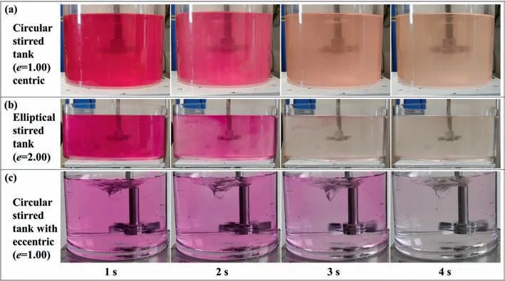
Fig.5.Transient diagrams at different times at Re=31600(the first,second,third,and fourth second after feeding):(a)in a circular stirred tank with centric impeller;(b)in an elliptical stirred tank with centric impeller;(c) in a circular stirred tank with eccentric impeller.
It is interesting to note that previous work confirmed that eccentric systems can reduce mixing time because of the local asymmetric space of the eccentric system [15,18].In fact,there is also a significant local asymmetric space in elliptical vessels(Fig.6(b) blue shaded area),which can enhance turbulence levels as well as induce chaotic mixing.It is also clear that the mixing time depends mostly on the local turbulence,which is controlled by the local turbulence where the region is most difficultly mixed in the laminar flow [33].However,in the case of turbulence,the region that most difficultly been affected by turbulence always is the farthest one form the blades.

Fig.6.Geometric diagrams of cross-section for (a) eccentric system and (b) elliptical system.
The comparison between the eccentric system and elliptical system is displayed in Table 5 and Fig.6.The longest distances of eccentric and elliptical systems are 15.1,and 15.0 centimeter,respectively;and the shortest distances of the eccentric and elliptical systems are 6.1,and 7.5 centimeter,respectively.Although there is minor difference in distance of the largest of two systems,the geometric of the eccentric system is significant different from the elliptical system.It is obvious that the farthest spatial structure of the elliptical system is the narrowest,while the farthest spatial structure of the eccentric system is broad.Therefore,the level of local turbulence at the far ends in the elliptical system is higher than that in the eccentric system.The improvement of local turbulence is the main contribution to decrease the mixing time.

Table 5 Comparison of the distance between the shaft with the sidewall in elliptical stirred system and eccentric stirred system
3.2.Effect of e on two-dimension streamline
The analysis in Section 3.1 suggests that elliptical stirred tanks can shorten mixing time as effectively as an eccentric system.However,the reason for this decrease in mixing time requires a deeper analysis of turbulent flow field.
In this section,we analyze the dependence of the evolution of turbulent flow field on the non-constant radius stirred tank.Fig.7 shows the structure of the cross-section of the streamline and its evolution witheincrease.It is apparent that the streamline vortex in the paraxial region decreases gradually until it disappears witheincrease.On the contrary,the streamline vortex in the abaxial region increases gradually both the quantity and volume,as shown by the blue arrow mark(see Fig.7Pz=0(a)to(e)).This result suggests that the streamline structure in both regions is different as the interaction between the impeller and sidewall is different in term of cross-section ofz=0.

Fig.7.The structure of the cross-section of the streamline at Re=31600.Vertically,(a),(b),(c),(d),(e) correspond to e=1.00,1.25,1.50,1.75,and 2.00,respectively.Horizontally, Pz=0, Px=0, Py=0,correspond to the cross-section of z=0, x=0, y=0,respectively.
It is obvious that cross-sectionx=0 is getting narrower and the cross-sectiony=0 is getting wider.As we know,the shape of streamline generated by a Rushton turbine is usually divided into two parts both above and below the blades.Similarly,this analysis also aims at the main flow cycles above and below the blades.In this case ofPx=0,the vortex center of the streamline above the blades increases with an increase ineat the paraxial regions until it reaches the top of liquid phase,as shown by the green arrow mark (see Fig.7Px=0(a) to (e)).Additionally,the most significant effect below the blades is that the discharge angle(β)changes from an acute angle to an obtuse angle,as shown by the red arrow mark(see Fig.7Px=0(a)to(e)).This means that a part of the fluid can be injected directly under the blades.In the case ofPy=0,the obvious influence is located at the farthest end.Specifically,the main flow cycles below the blades are superimposed with these above them,resulting in main flow cycles rewinding in the farthest region,as shown in the red box (see Fig.7Py=0(e)).Therefore,the coherent structure interface between above and below main flow circulation is broken by the rewinding circulation,which can enhance chaotic mixing in stirred tanks.
Although the streamline structure clearly shows the evolution of the global flow field,more details are needed to understand the changes of the local flow field.Therefore,CFD-post was used to extract the cloud image of radial velocity and the velocity vector image of the cross-section ofz=0,as shown in Fig.8.In this case,only a comparison betweene=1.00 ande=2.00 was conducted,which was able to show that elliptical tank configuration has an effect on the local flow field.

Fig.8.The comparison of flow field for e=1.00 and e=2.00 at Re=31600: (a),(b) are the color images of radial velocity of e=1.00,and e=2.00 at the cross-section z=0,respectively;(c),(d)are the velocity vector images of e=1.00,and e=2.00,respectively,at the cross-section z=0;(e),(f)are the transient images of the real field in steady station for e=1.00,and e=2.00,respectively,at the free surface.
It is observed,as displayed in Fig.8(a) and (b),the value ofzdirection velocity in the elliptical system is greater than the circular system.This suggests that axial velocity can be increased availably by changing the distance between the impeller and sidewall.In addition,the vector of velocity ofe=2.00 is more complex thane=1.00,as shown in the Fig.8(c)and(d).In the case ofe=1.00,the direction of the velocity vector is basically the same (see Fig.8(c).Indeed,circular motion of the fluid around central axis (see Fig.8(e)) is not conducive for mixing both radial and axial flows.This result gives an indication that velocity is too regular to facilitate chaotic mixing.In contrast,in the case ofe=2.00,complex motion can be observed in Fig.8(d) instead of regular circular motion.Specifically,bifurcation of vector of velocity occurs at region far from axis (see red dashed line in Fig.8).Velocity vector radiating around also accompanies in the abaxial region (see the I and V in Fig.8).At the paraxial region,trend of velocity vector shows characteristics of eddy motion instead of circumferential motion (see the II,III,and IV in Fig.8).Correspondingly,transient image of real field of flow in elliptical system is shown in Fig.8(f),which is in good agreement with diagram of velocity vector in Fig.8(d).
The analysis of the above paragraph reveals that the variations in flow filed structure between thee=1.00 ande=2.00 are the consequence of the asymmetric interaction force between the lateral sidewall and the impeller.Fig.8(c)and(d)show two images of velocity vectors at cross-sectionz=0.A natural comprehending of these results might suggest that the level of turbulence in both systems should be very different as the structure of velocity vector is very different.A deeper analysis,combination with Fig.8(e)and(f),is necessary if we would like to know the true state of turbulence.Indeed,a large number of secondary eddies (see Fig.8(f)) whose direction of flow is different from the main flow (counterclockwise) occur at the far-axis region.Therefore,there is no a strong central vortex in the E-UST(e=2.00).This might be a consequence that the secondary eddies replace the central vortex.Furthermore,the results would also suggest that chaotic mixing in the E-UST occurs due to an increase in turbulence level.
As mentioned Section 3.1 above,to validate the pattern of the main flow between the lateral sidewall and shaft of impeller,some information can be observed by the vortex velocity in both crosssection:Px=0,Py=0.Fig.9(c)displays a common pattern in a circular stirred vessel,regardless of any cross-section passing thought thez-axis.However,in the elliptical configurations case,two sections are representative: the first is thePy=0cross-section which is the biggest one in all cross-sections vertically;the second is thePx=0cross-section which is the minimum one.Hence,these two crosssections are selected as the typical plane to analyze the asymmetric characters in the vessels,as shown in Fig.9(a)and(b).It can be seen from Fig.9(a)that the main flow cycle in the E-UST(e=2.00)is no longer like the basically symmetrical cycles in a circular vessel(e=1.00),but presents a significant asymmetric feature,which can also be observed in Fig.9(b).The asymmetry in the E-UST makes this chaotic flow filed where significant fluid exchange between secondary eddies and main flow is achieved.In our previous work,we already point out that this exchange can be performed duo to coupling of vortex and turbulence,which can realize the object of chaotic mixing [26].
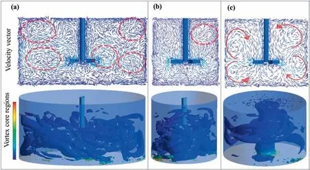
Fig.9.Comparisons of cross-section(Py=0)velocity vector,and the vortex core region at the same swirling strength:(a),(b)Py=0,Px=0 in the E-UST(e=2.00),respectively;(c)Py=0 in the C-UST (e=1.00).
Fig.9 shows the cross-section(Py=0)velocity vector and the vortex core region at the same swirling strength.Complex circulation loops can be seen in Fig.9(a)and(b),such as in the red circle,while in Fig.9(c)there are mainly four circulation loops,two at the above and below of the blades.Meanwhile,vortex core region was established in the CFD-post,swirling strength method was selected,and the level was set to 0.01,as shown in the bottom row of Fig.9.From the analysis of the vortex core region,it is known that the vortex core region in the E-UST (e=2.00) is larger than that in the C-UST (e=1.00),and the dispersion is relatively uniform.This indicates that more vortexes/eddies are formed in the elliptical vessel,resulting in strengthening the intensity of turbulence.
3.3.Effect of e on flow field velocity
The most important parameter in fluid dynamic is velocity,which is difficult to obtain in the real flow field.In this section,we analyze the velocities of three parts (r/R=0.75,0.50,0.25) of both the paraxial region (Lnear) and abaxial region (Lfar),as shown in Fig.10.We discussed three characteristic parts: an inner and an outer zone where the velocity change is most significant,and another region between both parts where is a bridge of speed between the inner and outer areas.It should be noted that we only discuss the details of the outer area where the difference of absolute velocity is most significant;the another two regions where the difference of absolute velocity is narrow.In the abaxial region(Fig.10(a)–(c)),with an increase ine,it is obvious that velocity changes in both size and direction (expressed by positive or negative).It can be observed that the direction of radial velocity changes suddenly to negative whene=2.00,and the distribution of radial velocity is more narrow fore=2.00 compared to other cases.In addition,this result indicates that the distribution of tangential velocity is similar to that of radial velocity.Moreover,the axial velocity has a wider distribution compared to others;however,its maximum velocity deviates from the tip of blades and might move up or down instead of occurring the tip of blades.It is because that non-constant radius,which generates an asymmetric main flow between blades and sidewalls.Thus,coupling between secondary flow (eddies) and main flow is stronger than coupling ine=1.00.
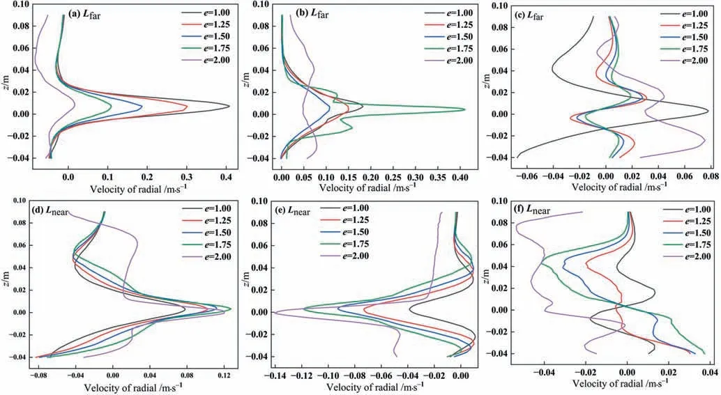
Fig.10.The distribution of absolute velocity at both paraxial region(Lnear)and abaxial region(Lfar)at Re=31600:(a)–(c)are the radial,tangential,and axial velocity in the Lfar,respectively;(e)–(f) are the radial,tangential,and axial velocity in the Lnear,respectively.
In the paraxial region,as shown in Fig.10(d)–(f),there is also a sudden change in radial velocity as the distance from the tank axis decreases with an increase ine.Furthermore,tangential velocity increases with an increase ine,while axial velocity distribution becomes more complex,resulting in an increase in axial velocity(see the Fig.10(e)).Consequently,the chaotic mixing level may be promoted by the complex velocity caused by the coupling motion of abundant secondary eddies(see the Fig.10(f)).This analysis reveals that the main effect of the non-constant radius configuration on local velocity is located at the outer region near the lateral sidewall.
3.4.Effect of e on turbulence kinetic energy
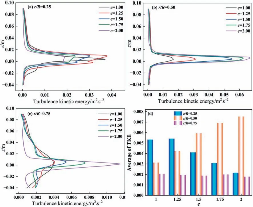
In this Section,to know the effect of non-constant radius on the chaotic mixing level,the TKE would be discussed,which can give another novel view on the turbulence behavior in elliptical vessels.Fig.11 shows the variation of TKE withein the abaxial region(Lfar).As shown in Fig.11(a),TKE increases gradually aseincreases from 1.00 to 1.75.While,TKE decreases gradually aseincrease from 1.75 to 2.00.In the vertical direction,TKE increases significantly in the area near the blade,while in the upper part of the blade(z>0.03),TKE increases gradually aseincreases from 1 to 1.75,and reaches its minimum value ate=2.00.In the lower region of the blade (z<–0.02),TKE remains almost constant with changes ine.In the middle region of the blade (–0.02 Fig.11.The distributions of TKE in the abaxial region (Lfar) at Re=31600. The results show that wheneincreases from 1.00 to 1.75,TKE increases in both upper and lower areas of stirred tanks,while still increasing in the middle region.The data indicates that TKE effectively increases in the range ofe=1.00 toe=1.75,which strengthens energy transfer and diffusion.This is probably a consequence that an increase inechanges periodic circumferential flow in the vessel and enhances the turbulent fluctuation of velocity.It is important to note that whenr/R=0.75eincreases,TKE decreases duo to the distance betweenr/R=0.75 and the shaft as shown in Table 6. Table 6 Distance of the monitoring line (Lfar) from the shaft in the abaxial region (mm) Whenr/R=0.75,the distance betweene=2.00 ande=1.00 from the stirring shaft is 112.5 mm and 79.5 mm,respectively,which increases by about 41.5%.At the larger transmission distance,TKE is dissipated and lost along the range,resulting in a gradual decrease of TKE witheincrease from 1.00 to 1.75.However,TKE distribution shows the opposite pattern ate=2.00.A comparison can be made between the E-USTs and the eccentric stirred system.The most conspicuous change in the eccentric installation of the stirring shaft is the distance between the shaft and the sidewall,which changes from a constant quantity to a variable one that is similar with E-USTs.It has been shown that TKE increases gradually to an extreme value with increasing eccentricity and then decreases with an inflection point corresponding to an eccentricity of about 0.45.Perhaps there is a correlation betweeneand eccentricity,and although a quantitative correspondence between the two has not been established,it is foreseeable that elliptical and eccentric mixing are intrinsically linked in terms of turbulence enhancement. Fig.12 shows the variation of TKE withein the near-axis region.Fig.12(a)–(c)correspond to TKE distributions atr/R=0.25,0.5,and 0.75,respectively.Whenr/R=0.25 and 0.5,the TKE distribution pattern is basically consistent with the far-axis region.However,whenr/R=0.75,inconsistency occurs in the middle region of vertical direction(–0.02 Table 7 Distance of the monitoring line (Lnear) from the shaft in the paraxial region (mm) Fig.12.The distributions of TKE in the paraxial region (Lnear) at Re=31600. Whenr/R=0.75,the spatial distance ofe=2.00 is reduced by about 29.2% compared toe=1.00,which is close to the stirring shaft and undoubtedly increases the TKE values.Fig.12(d)depicts the relationship betweenevariation and average TKE in the near-axis region,which visualizes the trend of the effect ofeon TKE.It can be seen that TKE decreases aseincrease from a 1.00 to 2.00 atr/R=0.25,while TKE increases aseincrease from 1.00 to 1.75 and reaches its maximum value ate=1.75,later decreases.Similarly,the trend of changes in TKE atr/R=0.5 is similar to atr/R=0.5,while its value is always smaller than atr/R=0.75. Table 8 shows that TKE decreases gradually as the distance monitor line from the shaft increases in the abaxial region,whereas TKE reaches the maximum value atr/R=0.5 in the paraxial region. Table 8 Average values of turbulent kinetic energy in both regions (m2∙s-2) The mixing time and turbulent flow field characteristics in noconstant radius(variable diameter)stirred tanks were investigated numerically and experimentally.The following are the key findings: 1) Elliptical shape vessels can effectively reduce the mixing time,which is decreased by 45.3% ate=2.00. 2) Elliptical shape vessels are an improvement on the eccentric stirring system,which has the advantage of eccentric stirring while overcoming the deficiency of unbalanced force. 3)In comparison to flow field in the far-and near-axis region in elliptical tanks,there is significant local asymmetry,including the height of circulation center,the size of discharge angle and the transfer of TKE. 4) Development of secondary flow in elliptical vessels is promoted availably,as well as the distribution of vortex strength becomes more uniform aseincrease. 5) Axial velocity in elliptical vessels is the most sensitive toe,while both circumferential velocity and radial velocity change obviously untilegreater than 1.75. Data Availability Data will be made available on request. Declaration of Competing Interest The authors declare that they have no known competing financial interests or personal relationships that could have appeared to influence the work reported in this paper. Acknowledgements This work was supported by the National Key Research and Development Project (2022YFB3504305,2019YFC1905802),National Natural Science Foundation of China (22078030),Joint Funds of the National Natural Science Foundation of China(U1802255),Key Project of Independent Research Project of State Key Laboratory of Coal Mine Disaster Dynamics and Control(2011DA105287-zd201902),Three Gorges Laboratory Open Fund of Hubei Province (SK211009,SK215001). Nomenclature C0initial concentration of the tracer,% Ctconcentration of the tracer at timet,% C∞final concentration of the tracer,% Dimpeller diameter,mm Didisc diameter,mm eratio of long diameter to short diameter ggravitational acceleration,m∙s-2 Hliquid height,mm HCoff-bottom clearance,mm Lfarmonitoring line in the far-shaft region Lnearmonitoring line in the near-shaft region Nimpeller speed,r∙min-1 Pinfeed point Pxplane ofx=0 Pyplane ofy=0 Pzplane ofz=0 P1monitoring point 1 P2monitoring point 2 P3monitoring point 3 P4monitoring point 4 ppressure,Pa Rdistance between the shaft and sidewall,mm rdistance between the shaft and monitor,mm Stank bottom area,mm2 Tmaxtank long diameter,mm Tmintank short diameter,mm ttime,s vvelocity,m∙s-1 Wblades width,mm θ mixing time,s μ dynamic viscosity,Pa∙s ρ density of liquid,kg∙m-3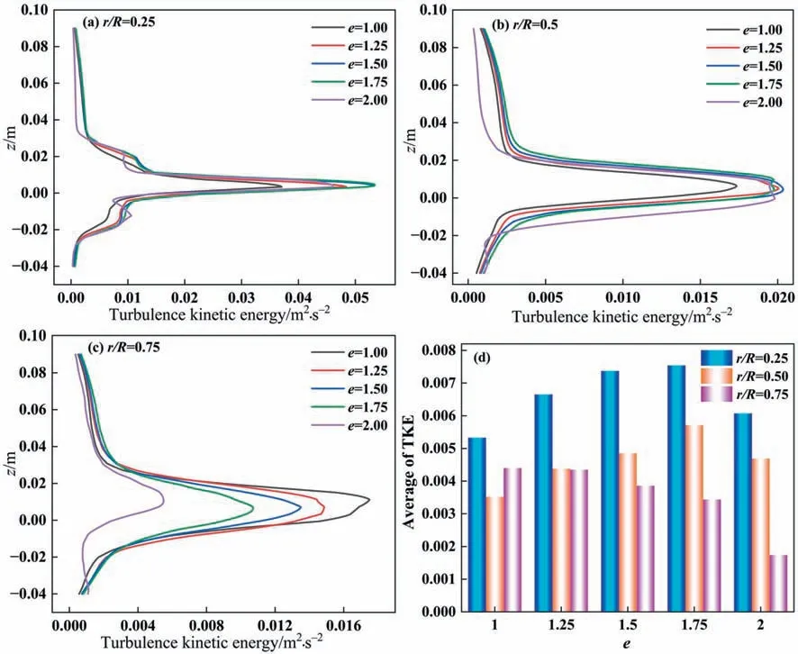



4.Conclusions
杂志排行
Chinese Journal of Chemical Engineering的其它文章
- Flower-like tin oxide membranes with robust three-dimensional channels for efficient removal of iron ions from hydrogen peroxide
- Experimental study on the activation of coal gasification fly ash from industrial CFB gasifiers
- Enhanced stability of nitrogen-doped carbon-supported palladium catalyst for oxidative carbonylation of phenol
- Solubility of iron(III) and nickel(II) acetylacetonates in supercritical carbon dioxide
- Filtration performance and modeling of granular bed for dust removal from coal pyrolytic vapors
- Copper slag assisted coke reduction of phosphogypsum for sulphur dioxide preparation
