Damage Evolution of Ballastless Track Concrete Exposed to Flexural Fatigue Loads: The Application of Ultrasonic Pulse Velocity,Impact-echo and Surface Electrical Resistance Method
2024-04-11YANGZhiqiangLIHuajianWENJiaxingDONGHaoliangHUANGFaliWANGZhenYIZhonglai
YANG Zhiqiang ,LI Huajian,3* ,WEN Jiaxing ,DONG Haoliang ,HUANG Fali ,WANG Zhen ,YI Zhonglai
(1.Railway Engineering Research Institute,China Academy of Railway Science Corporation Limited,Beijing 100081,China;2.State Key Laboratory for Track System of High-Speed Railway,Beijing 100081,China;3.School of Civil Engineering,Beijing Jiaotong University,Beijing 100044,China)
Abstract: In order to clarify the fatigue damage evolution of concrete exposed to flexural fatigue loads,ultrasonic pulse velocity (UPV),impact-echo technology and surface electrical resistance (SR) method were used.Damage variable based on the change of velocity of ultrasonic pulse (Du) and impact elastic wave (Di)were defined according to the classical damage theory.The influences of stress level,loading frequency and concrete strength on damage variable were measured.The experimental results show that Du and Di both present a three-stages trend for concrete exposed to fatigue loads.Since impact elastic wave is more sensitive to the microstructure damage in stage III,the critical damage variable,i e,the damage variable before the final fracture of concrete of Di is slightly higher than that of Du.Meanwhile,the evolution of SR of concrete exposed to fatigue loads were analyzed and the relationship between SR and Du,SR and Di of concrete exposed to fatigue loads were established.It is found that the SR of concrete was decreased with the increasing fatigue cycles,indicating that surface electrical resistance method can also be applied to describe the damage of ballastless track concrete exposed to fatigue loads.
Key words: ballastless track;fatigue damage;ultrasonic pulse velocity;impact-echo;surface electrical resistance
1 Introduction
It is reported that 73,000 km high-speed railways have been constructed in the world by the end of 2021,in which China accounts for nearly 55% of the whole mileages of high-speed railways.Ballastless track,whose main component is concrete,is the direct bearing structure for the periodic loads induced by the highspeed running trains.Take China Railway Track System (CRTS) III slab ballastless track,for example.The track structure consists of prefabricated concrete track slab,self-compacting concrete (SCC),geotextile track as well as base plate concrete from top to bottom[1,2].Compared with normal concrete,ballastless track slab concrete is steam-cured and the strength grade is higher than C50[3].Expect for the static loads,temperature change and aggressive ions from the environment,fatigue damage induced by the train loads is another main deterioration reasons leading to the failure of ballastless track concrete structures[4].It shows that vertical ground vibration acceleration is up to 0.1 g,while the geometrical characteristic frequency is up to 128.2 Hz when the running speed of high-speed train is 300 km/h[5].Therefore,in order to guarantee the safety of the running high-speed train,Chinese standard TB 10621-2014[6]suggests a dynamic load magnification factor of 3.0 and 2.5 for the train speed of 300 and 250 km/h,respectively.
In order to predict the service life of concrete under fatigue loads,the study on fatigue damage assessment of concrete is of great significance[7].Up to date several approaches have been put forwarded and developed to evaluate the fatigue damage of concrete.Zenget al[8]claimed that secant elastic modulus of ballastless track self-compacting concrete is decreased with the increasing fatigue cycles,and fatigue hardening occurred during fatigue loading.Also,the residual strength of concrete is found to be decreased after being subjected to fatigue loads[9].Chenet al[10]suggested a damage variable considering the ratio of strain increment to the ultimate strain of concrete subjected to fatigue loads.Caoet al[11]recommended that the ratio of residual strain to the ultimate residual strain before the final fatigue fracture could be employed to evaluate the damage of concrete when exposed to fatigue loads.Meanwhile,dissipated energy method (DEM) method was also applied to describe the fatigue damage of concrete since it can describe the fatigue damage more accurately as considering the stress and strain concurrently and can reflect the continuous damage in the stationary stage[12].Although these methods were successfully used to describe the fatigue damage of concrete,they are either destructive or too complicated.Non-destructive testing (NDT) is an advanced technology that can be employed to characterize the properties and microstructure of material without destroying the serviceability[13].In concrete study field,acoustic emission technique (AE)[14],X-ray computed tomography(X-CT)[15],electrical resistance[16]andetc.,have been successfully used to estimate the degree of damage.
The objective of this experiment is to investigate the evolution of fatigue damage of ballastless track concrete by ultrasonic pules velocity,impact-echo and surface electrical resistance method.Based on the obtained wave velocity,the effect of stress level,loading frequency and strength grade of concrete on fatigue damage variableDuandDiwere investigated.Meanwhile,the relationship between SR andDu,the relationship between SR andDiwere discussed.
2 Principles of NDT methods and damage variable
2.1 Ultrasonic pulse velocity
Classical damage theory[17]suggested that the change of Young’s modulus (Ed) is defined as damage variable for concrete subjected to external aggressive and damage process.However,different with the staticEd,the dynamicEdcannot be measured directly.Ultrasonic wave test,including resonant frequency[18]and ultrasonic pulse velocity (UPV)[19],are classical nondestructive method for evaluating the damage of concrete materials.Fig.1 displays the principle and UPV test setup.It is well-known that the propagation of ultrasonic wave is related to the elastic properties and the density of the material[20].

Fig.1 Principle and schematic of UPV test of concrete
According to the principle of UPV method,when ultrasonic is propagated in three-dimensional direction,i e,in semi-infinite elastic solids,the dynamicEduof concrete can be calculated as Eq.(1),
where,ρandυare the apparent density and dynamic Poisson’s ratio of concrete,respectively;Vuthe velocity of the ultrasonic wave.The damage variableDubased on UPV test can be expressed as Eq.(2),
where,VunandVu0are the transport velocity of ultrasonic wave in concrete specimen afterncycles of fatigue loads and before fatigue cycles.
2.2 Impact-echo technology
Impact-echo technology,originally invented to detect the flaws in plate-like materials and structures[21],is an acoustic method by analyzing the response frequency of through media caused by an impact load[22-24].With the effect of elastic impact,low-frequency stress waves are generated and propagated in concrete,as shown in Fig.2(a).The test setup of impact-echo method for concrete is presented in Fig.2(b).

Fig.2 Principle and schematic of impact-echo test of concrete
According to the principle of impact-echo method,stress waves are reflected at flaws or surfaces of concrete specimen,forming transient resonances that can be distinguished by the frequency spectrum and amplitude.The transport velocity of impact elastic wave in the plateVican be calculated as follows:
where,Tis thickness of the plate;fthe frequency of P-wave in plate.Sansaloneet al[26]claimed thatViis approximate 96% of the transport velocity ofP-wave in semi-infinite elastic solids (calculated from Eq.(1)).However,as the bar-like shape of the specimen in this paper,Viis proved to be corresponded well with the transport velocity of ultrasonic wave in one-dimensional direction[27].Thus,the dynamic elastic modulus (Edi)could be obtained as Eq.(4),
Likewise,the damage variable based on impact-echo test can be expressed as Eq.(5),
where,VinandVi0are the transport velocity of impact elastic wave in concrete specimen afterncycles of fatigue loads and before fatigue cycles.
2.3 Surface electrical resistance
Electrical resistance,showing the ability of concrete to resist the flow of electrical current,is generally considered as a decisive parameter for the durability of structural concrete[28-30].As for ballastless track concrete slab,the electrical resistance of which is one of the most important parameters[31].Up to now two-point method[32],four-point method (also called the Wenner method)[33]and ASTM C1760 test method[34]were developed and applied to evaluate the electrical resistivity of concrete.However,only the four-point methos is an NDT method[35].
The schematic of surface electrical resistance (SR)test by a four-probe method is demonstrated in Fig.3.The device consists of four equally spaced linear electrodes.A potential difference (V) is injected into the two internal electrodes,while the electrical current (I)through the other two outer electrodes is tested.

Fig.3 Principle and schematic of four-point Wenner probe test
Assuming that the electrodes are infinitely small and concrete specimen is semi-infinite with a homogenous resistivity[37],then the surface electrical resistance can be determined as follows,
where,ρais the apparent resistivity of concrete;athe distance between two electrodes;VandIthe applied voltage and current,respectively.
3 Experimental
3.1 Materials
In this experiment,PO 42.5 ordinary portland cement (C),class-I fly ash (FA),grade-S95 slag (SL) and silica fume (SF) were used.The chemical composition of binders used in this experiment were tested by an X-ray fluorescence (XRF) method,and the results are displayed in Table 1.The fundamental properties of cement are shown in Table 2.

Table 1 Chemical composition of the used cement,FA,SL,and SF/wt%

Table 2 Fundamental properties of the used cement
Natural river sand with a fineness modulus of 2.8,and crushed limestone with sizes of 5 -10 mm and 10-20 mm were employed as fine and coarse aggregate,respectively.Asilanized polycarboxylate superplasticizer (SP) with a water reducing rate of 27% was used for a desired fluidity of fresh concrete.
3.2 Mix proportions
The mix proportions of concrete are displayed in Table 3.The slump of the designed concrete is controlled in 160 ± 20 mm.Cubic specimen with a dimension of 100 mm × 100 mm × 100 mm,and prism specimen of 100 mm × 100 mm × 300 mm and 100 mm ×100 mm × 400 mm were casted in molds and vibrated to facilitate the compaction.After casting for 24 h,the concrete was demolded and cured in standard environment with temperature of 20 ± 2 ℃ and relative humidity of 95% for 90 days.The compressive strength,flexural strength and static modulus of elasticity of concrete were tested according to the Chinese standard GB/T 50081[38],and the results are presented in Table 4.

Table 3 Mix proportion of concrete/(kg/m3)

Table 4 Mechanical properties of the designed concrete at 28 days
3.3 Flexural fatigue test
The concrete specimens were moved out and stored at drying environment with a temperature of 20± 2 ℃ and a relative humidity of 60% for another 28 days after the standard curing.Subsequently,the flexural fatigue test was carried out.In this experiment,an electro-hydraulic fatigue testing machine constructed by Sansi Zongheng Technology Co.,Ltd.was employed.Since ballastless track concrete mainly suffers from the effect of flexural fatigue loads,in this paper,a third point loading method was used and the load control mode was applied with a sinusoidal waveform.The upper,lower limits of fatigue loads and loading frequency are demonstrated in Table 5.One can see that the stress level of the first group (C60S0.6F20 and C60S0.7F20) is 0.6 and 0.7 with a loading frequency of 20 Hz,respectively.For concrete specimen group two,the stress level was fixed at 0.6 while the loading frequency was 5,10,and 15 Hz.Meanwhile,the flexural fatigue resistance of C40 and C80 concrete were also conducted at a stress level of 0.6 and a loading frequency of 20 Hz.The stress ratio is fixed at 0.1 for all specimens.

Table 5 Experimental parameters of flexural fatigue tests of ballastless track concrete
After being subjected to flexural fatigue loads for certain cycles,the concrete specimens were removed and tested with the following NDT methods.
3.4 NDT methods
The UPV method was used to evaluate the degree of fatigue damage of ballastless track concrete.In this experiment,a nonmetallic ultrasonic instrument constructed by Tianhong Co.,Ltd.was used to measure the ultrasonic wave velocity.Based on the experimental results,the dynamic elastic modulusEduand damage variableDuwere calculated according to Eq.(1) and Eq.(2).
The velocity of the impact elastic wave of damage and undamaged concrete were also measured according to the Chinese standard JGJ/T 411-2017[39].An impact-echo instrument manufactured by Sichuan Shengtuo Co.,Ltd.was applied.The impact elastic wave was triggered by a steel sphere with a diameter of 17 mm on the center of concrete specimen sides.After that,the dynamic elastic modulusEdiis determined by Eq.(4) and the damage variable is obtained by Eq.(5).
The surface electrical resistance of concrete subjected to flexural fatigue loads was measured according to the Ref.[40].In this paper,a Proceq Resipod concrete resistivity meter were used.Before testing,the lower surface (tensile zone concrete) was saturated with a wet towel for 10 minutes.
4 Results and discussion
4.1 Damage variable Du and Di of concrete exposed to fatigue loads
4.1.1 Influence of stress level
The fatigue life of C60 concrete exposed to fatigue loads with a stress level of 0.6 is 792533,835616,975681,1020752,1090471,and 1252343 cycles,respectively.The average life of concrete specimen is 994566 cycles.Numerous studies show that the damage of concrete follows a three-stages process,i.e.,nucleation of microcracks,stable damage expansion and unstable damage development[41].The damage variableDuversus normalized cycles,Diversus normalized cycles of concrete are exhibited in Fig.4(a).It can be seen that a typical three-stages trend was observed for both the development ofDuandDi,and the ratio of stage I,II and III to the whole life is around 5%,85% and 10%,respectively.Particularly,in stage I,the damage variableDuandDiis increased sharply.After that,the damage variableDuandDiare increased at a very slow speed,i e,stage II.Then,for concrete in stage III,with the increase of fatigue cycles,the damage variableDuandDiare increased significantly to 0.2 and 0.21,respectively.

Fig.4 Damage variable Du and Di of C60 concrete exposed to flexural fatigue loads at stress level of 0.6 and 0.7
The fatigue life of C60 concrete subjected to flexural fatigue loads with a stress level of 0.7 is 54927,68323,84396,85643,103625,and 82021 cycles,and the average life is 79822 cycles.It is clear that when the stress level is increased from 0.6 to 0.7,the fatigue life is deceased significantly.As shown in Fig.4(b),bothDuandDiincrease with normalized cycles.Unfortunately,as the transport of ultrasonic wave and impact elastic wave were measured every 20,000 cycles,the three-stages damage evolution trend is not apparent.Because the impact elastic wave is more sensitive than ultrasonic wave for detecting the fatigue damage of concrete,the damage variableDuis general lower thanDifor concrete exposed to fatigue loads.
4.1.2 Influence of loading frequency
Loading frequency is one of the most vital parameters for the fatigue resistance of concrete.The influence of loading frequency on the damage variable of C60 concrete is shown in Fig.5.It is clear that regardless of the loading frequency,the damage variableDuandDiboth show a three-stages trend.Meanwhile,the durability of each stage of the damage variable of concrete changes with the loading frequency.For instance,the ratio of stage I on the whole life of concrete exposed to fatigue loads with a frequency of 5 Hz is about 15%,but it decreased to only approximate 5% for concrete with a loading frequency of 10,15,and 20 Hz.Fig.6 presents the fatigue life of concrete specimens exposed to flexural fatigue loads at various loading frequency.It can be seen that the influence of loading frequency on fatigue life is not apparent,which is consistence with the Ref.[42].The critical damage variable of concrete exposed to different loading is exhibited in Table 6.It is clear that when the loading frequency is 5 Hz,the critical damage variableDuandDiare higher than 0.3.However,with the increase of loading frequency,the critical damage variable is decreased.Since the microcracks opening in concrete exposed to a lower loading frequency is smaller than concrete exposed to a higher loading frequency,the faster transient stress states lead to a lower progression of microcracks,resulting in the decrease of the critical damage variable.Therefore,the critical degree of fatigue damage of concrete at a loading frequency of 5 Hz is higher than that of concrete under higher loading frequency.
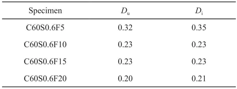
Table 6 The critical damage variable of C60 concrete exposed to fatigue cycles with different loading frequencies

Table 7 The critical damage variables of concrete with various strengths

Fig.5 Damage variable Du and Di of C60 concrete exposed to fatigue loads with different frequencies
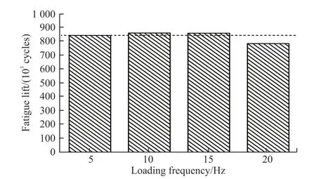
Fig.6 Influence of loading frequency on fatigue life of C60 concrete
4.1.3 Influence of concrete strength
The fatigue behaviors of C40 and C80 concrete were also measured.When concrete was exposed to flexural fatigue loads with a stress level of 0.6 and a loading frequency of 20 Hz,the average fatigue life of C40 and C80 concrete is 889071 and 1240445 cycles.On one hand,from the view of composite material,since the compaction of interface transfer zone (ITZ) of concrete is increased due to the lower water cement ratio (higher strength grade),the fatigue life is improved with concrete strength[43].On the other hand,from the view of energy,as the dissipated energy per cycle of concrete exposed to fatigue loads is decreased with the increasing strength grade[44],the fatigue life is increased with increasing strength grade.
Generally,for concrete exposed to fatigue cycles,the cycle ratio at the end of stage I and the beginning of stage III are donate ask1andk2,respectively.The damage evolution of C40,C80 and C60 concrete are demonstrated in Fig.7 and Fig.4(a).It can be seen that the duration of stage I in C40 concrete is about 2% of the whole fatigue life,however,it increases to about 6%and 10% for C60 and C80 concrete,respectively.As summarized by Leeet al[45],the damage firstly occurred around the existed flaws and microcracks in this stage.That is,the damage was accumulated sharply at ITZ,i e,the weak area inside the concrete.With the increase of compressive strength of concrete,the mechanical properties of ITZ are increased,thus resulting in the slower increase of fatigue damage variable.In stage II,the microcracks was slowly propagated and formation under fatigue loads,and the damage variable was steady developed.With the further increase of fatigue cycles,the microcracks were coalesced and the macrocracks were further formed,thus the damage variable was increased dramatically.As the brittleness of concrete was increased with the increasing strength grade,the duration of stage III for C80 concrete is lower than that of C60 and C40 concrete[46].Furthermore,the critical damage variable of concrete subjected to flexural fatigue loads are presented in Fig.7.Since the dissipated energy per cycle of concrete exposed to fatigue loads is decreased with the increasing strength grade[44],the order of critical damage of concrete is C80 >C60 >C40.

Fig.7 Damage variable Du and Di of C40 and C80 concrete exposed to flexural fatigue loads
4.2 SR of concrete exposed to fatigue loads
4.2.1 SR evolution of concrete
Figs.8-10 show the SR of concrete exposed to flexural fatigue loads.It can be seen that the SR is decreased regardless of the stress level,loading frequency and strength grade of concrete of fatigue loads and concrete specimen.Boulayet al[47]claimed that the electrical resistance of concrete was constant when no crack was formed,however,it was decreased when a crack was initiated.Furthermore,It shows that the electrical resistance is related to cracks extent of concrete samples[48].Since the porosity of tensile zone concrete is found to be increased and crack-like pores are formed with the effect of flexural fatigue loads[49],the SR of tensile zone concrete is decreased with the increasing fatigue cycles.Besides,it is found that the development of SR of concrete also exhibits a three-stages trend,i e,the SR is decreased sharply in the beginning of fatigue cycles;the SR is steady decreased with the effect of fatigue loads;the SR is decreased significantly before the final fracture,indicating that the change of SR of concrete is related to the internal damage of concrete exposed to fatigue loads.
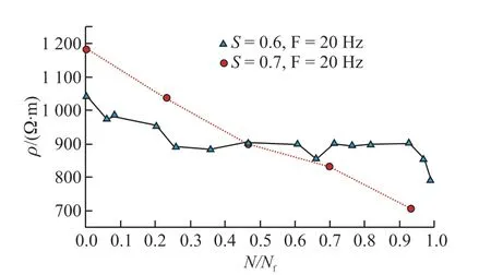
Fig.8 SR of C60 concrete exposed to flexural fatigue loads (F=20 Hz,S=0.6 and 0.7)
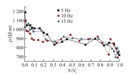
Fig.9 SR of C60 concrete exposed to flexural fatigue loads (S=0.6,F=5,10,and 15 Hz,respectively)
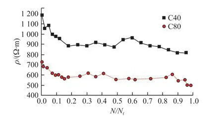
Fig.10 SR of C40 and C80 concrete exposed to flexural fatigue loads (S=0.6,F=20 Hz)
4.2.2 Relationship between SR and damage variableDuandDi
Research shows that the damage variableDis linearly with the effective density of microcracks[50],as shown in Eq.(7),
where,Dis the damage variable measured by acoustic emission method,i e,damage variableDuandDiin this paper;ma constant that related to the Poisson’s ratio of concrete;εthe effective density of microcracks.
When concrete is exposed to fatigue loads,the microcracks are formed and further increased with the increasing fatigue cycles[51].Assuming that the density of microcracks equals to the increase of porosity,that is,
where,φcis the porosity of concrete exposed to fatigue loads;φ0the initial porosity of intact concrete.
On the other hand,concrete can be seen as the composite material of pore solution and gas-solids phases.According to the conductivity of two phases materials[52],the conductivityσof concrete can be determined as follows,
where,σ1is the conductivity of liquid in concrete;σ23the composite conductivity of gas-solid phases;φ1the volume fraction of liquid in concrete;Scthe porosity of concrete;φcthe degree of saturation of concrete.
It is apparent thatσ1is far higher thanσ23,thus Eq.(9) can be simplified as,
For concrete exposed to fatigue cycles,the porosity of concrete and the degree of saturation of concrete can be calculated as,
where,εvis the volumetric strain;S0the initial degree of saturation of concrete.
Considering Eq.(11),Eq.(12),and Eq.(13) one obtains,
or the electrical resistance of concrete can be expressed as,
The porosity of concrete can be written by inserting Eq.(15) into Eq.(12):
Therefore,the electrical resistance of concrete under fatigue loads should be,
where,a,bandcare fitting parameters,which are related to the initial porosity of concrete,the initial degree of saturation and conductivity of pore solution in concrete.
The fitting curves between SR andDu,SR andDiof concrete exposed to flexural fatigue loads are shown in Figs.11 -13.It is shown that theR2for all specimens are higher than 0.61,indicating that SR is related to the degree of fatigue damage of concrete.Although theR2between SR andDuis higher than that between SRandDifor some cases,the relationship between SR andDican be better fitted on the whole (higherR2).When flexural fatigue loads were added to concrete,the surface electrical resistance was decreased greatly due to the damage of existed flaws and initiation of microcracks in stage I.With the increase of fatigue cycles,i e,in stage II,the extension and nucleation of microcracks were steady propagated,thus the SR and damage variableDuandDidecreased slowly.When the fatigue damage was further developed to stage III,some macrocracks were formed with the accumulation of microcracks caused by fatigue loads,leading to the decrease of SR and damage variableDuandDi[45].This implies that the change of SR can also be applied to evaluate the fatigue damage of concrete.However,the damage variable based on the change of SR still need more works.
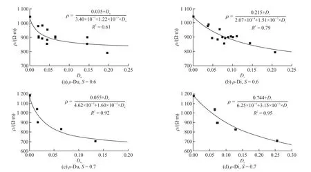
Fig.11 Fitting curves between SR and Du,SR and Di of C60 concrete exposed to fatigue cycles with a stress level of 0.6 and 0.7

Fig.12 Fitting curves between SR and Du,SR and Di of C60 concrete exposed to fatigue cycles with a loading frequency of 5,10,and 15 Hz

Fig.13 Fitting curves between SR and Du,SR and Di for C40 and C80 concrete exposed to fatigue loads
5 Conclusions
In this paper,non-destructive testing including ultrasonic pulse velocity,impact-echo and surface electrical resistance method were used to investigate the damage process of ballastless track concrete exposed to fatigue loads.Hereafter the following conclusions can be drawn:
a) Damge variableDuandDiboth show a three-stages trend for concrete exposed to fatigue loads,showing thatDuandDican be used to evaluate the degree of fatigue damge of concrete.However,as impact elastic wave is more sensitive to the formation of microcracks in stage III than ultrasonic pulse method,the critical damage variable ofDiis slightly higher than that ofDu.
b) Loading frequency shows a vital influence on the degree of fatigue damage of concrete.When concrete is exposed to flexural fatigue loads with a loading frequency of 5 Hz,the critical damage variable ofDuandDiare higher than 0.3,while they are decreased to approximate 0.2 when the loading frequency is higher than 10 Hz.
c) With the increase of strength grade of ballastless track concrete,the duration of fatigue damage stage I was prolonged due to the denser microstructure of concrete.Meanwhile,both the critical damage variableDuandDiwere increased slightly with concrete strength.
d) The development of SR of concrete as well exhibits a three-stages trend,indicating that the change of SR is related to fatigue damage of concrete.Although the coefficient of determination between SR andDuis higher than that between SR andDifor some cases,the relationship between SR andDican be better fitted on the whole.
Conflict of interest
All authors declare that there are no competing interests.
杂志排行
Journal of Wuhan University of Technology(Materials Science Edition)的其它文章
- Fabrication of YAG: Ce3+ and YAG: Ce3+,Sc3+ Phosphors by Spark Plasma Sintering Technique
- Preparation of Modified UiO-66 Catalyst and Its Catalytic Performance for NH3-SCR Denitration
- Effect of Molecular Weight on Thermoelectric Performance of P3HT Analogues with 2-Propoxyethyl Side Chains
- Ultraviolet Photodetector based on Sr2Nb3O10 Perovskite Nanosheets
- Fabrication of Silane and Desulfurization Ash Composite Modified Polyurethane and Its Interfacial Binding Mechanism
- Bio-inspired Hydroxyapatite/Gelatin Transparent Nanocomposites
