Characteristics of the SOL ion-to-electron temperature ratio on the J-TEXT tokamak with different plasma configurations
2024-03-19CunkaiLI李存凯YunfengLIANG梁云峰ZhongheJIANG江中和SongZHOU周松JiankunHUA华建坤JieYANG阳杰QinghuYANG杨庆虎AlexanderKNIEPSPhilippDREWSXinXU徐鑫FeiyueMAO毛飞越WeiXIE谢伟YutongYANG杨雨桐JinlongGUO郭金龙YangboLI李杨波ZhengkangREN任正康ZhipengCHEN陈志鹏
Cunkai LI (李存凯),Yunfeng LIANG (梁云峰),,*,Zhonghe JIANG (江中和),Song ZHOU (周松),Jiankun HUA (华建坤),Jie YANG (阳杰),Qinghu YANG (杨庆虎),Alexander KNIEPS,Philipp DREWS,Xin XU (徐鑫),Feiyue MAO (毛飞越),Wei XIE (谢伟),Yutong YANG (杨雨桐),Jinlong GUO (郭金龙),Yangbo LI (李杨波),Zhengkang REN (任正康),Zhipeng CHEN (陈志鹏),Nengchao WANG (王能超) and the J-TEXT Team
1 International Joint Research Laboratory of Magnetic Confinement Fusion and Plasma Physics,State Key Laboratory of Advanced Electromagnetic Engineering and Technology,School of Electrical and Electronic Engineering,Huazhong University of Science and Technology,Wuhan 430074,People’s Republic of China
2 Forschungszentrum Jülich GmbH,Institut für Energie- und Klimaforschung—Plasmaphysik,Partner of the Trilateral Euregio Cluster (TEC),Jülich 52425,Germany
Abstract Accurate measurement of the average plasma parameters in the edge region,including the temperature and density of electrons and ions,is critical for understanding the characteristics of the scrape-off layer (SOL) and divertor plasma transport in magnetically confined fusion research.On the J-TEXT tokamak,a multi-channel retarding field analyzer (RFA) probe has been developed to study average plasma parameters in the edge region under various poloidal divertor and island divertor configurations.The edge radial profile of the ion-to-electron temperature ratio,τi/e,has been determined,which gradually decreases as the SOL ion self-collisionality,increases.This is broadly consistent with what has been observed previously from various tokamak experiments.However,the comparison of experimental results under different configurations shows that in the poloidal divertor configuration,even under the same,τi/e in the SOL region becomes smaller as the distance from the X-point to the target plate increases.In the island divertor configuration,τi/e near the O-point is higher than that near the X-point at the same,and both are higher than those in the limiter configuration.These results suggest that the magnetic configuration plays a critical role in the energy distributions between electrons and ions at the plasma boundary.
Keywords: ion temperature,island divertor,poloidal divertor,retarding field analyzer (RFA) probe
1.Introduction
The average plasma parameters in the edge region,including the temperature and density of electrons and ions,are critical for understanding the characteristics of the scrape-off layer (SOL) and divertor plasma transport in magnetically confined fusion research.However,due to the limited diagnostic methods,the edge ion temperature is generally set to be equal to the electron temperature in many theoretical models.Research during recent decades has found that the ion temperature is not equal to the electron temperature [1,2],especially in the tokamak SOL region,where the ion temperature can be by a factor of 2 or even up to 5 higher than the electron temperature.Therefore,an accurate measurement of the edge ion temperature profile is required for conducting a proper edge plasma transport analysis.
The retarding field analyzer (RFA) probe has been developed and widely used for the measurement of the edge ion temperature profile in many fusion devices such as JET [3,4],Tore Supra [1],Alcator C-mod [5],ISTTOK [6],STOR-M[7,8],EAST [9],LHD [10],W7-X [11] and J-TEXT [12].A strong dependence of the edge ion-to-electron temperature ratio,τi/e,on the SOL ion self-collisionality,,has been observed in several tokamak experiments,which is consistent with the simulation results of two-dimensional (2D)edge transport codes,EDGE2D and onion-skin [13].Asincreases,τi/edecreases gradually,and the energy exchange between ions and electrons is more efficient whenis higher andτi/eis closer to 1.However,recent experimental results from the island divertor experiments on the W7-X stellarator demonstrated that the magnetic geometry could impact significantly on the energy partition between ions and electrons in the SOL region [14].A peaked plasma density structure induced by an infinite magnetic connection length structure is observed to destroy this SOL collisionality dependence ofτi/eand enhance the local ion-to-electron temperature ratio in a stellarator with an island divertor configuration.
In recent years,resonant magnetic perturbations (RMPs)have been considered as an attractive method to mitigate /suppress the type-I edge localized modes (ELMs) in tokamak H-mode plasmas and will be applied to ITER [15,16].With the application of RMPs,a 3D stochastic boundary consisting of remnant magnetic island structures and ergodic fields surrounding them will be formed.In addition to being used to control the type-I ELMs,this RMP-induced 3D plasma boundary can directly enhance the particle outflow at the edge and concomitantly increase the wetted area of power load onto the divertor target [17,18].The previous experimental results from the TEXTOR tokamak show that the typical effect of RMP on the edge plasma is the increase of plasma potential and the resultant variation on the ambipolar radial electric field,Er[19].Since the electrons move faster than massive ions along thestochastic field lines onto the wall,theEris stronglyenhanced or even reverses sign from negative to positive inmost of the 3D stochastic boundary region.Therefore,studying the effect of different boundary plasma configurations ontheτi/eis of great significance for understanding the differences between ion and electron transport channels.
On the Joint Texas Experimental Tokamak (J-TEXT),several new divertor configurations,including the high-fieldside middle-plane single-null (HFS-MSN) poloidal divertor and the island divertor,have recently been investigated [20].A new multi-channel RFA probe was installed for simultaneous measurement of edge profiles of the electron density and temperature,and ion temperature.In this paper,we describe the experimentally observed dependence of theτi/eon theand how it is altered by changing the divertor configuration on J-TEXT.
The remainder of this paper is organized as follows.Section 2 introduces the divertor configurations and the RFA probe on the J-TEXT tokamak.The influence of the X-point position on thedependence of theτi/ein the HFS-MSN poloidal divertor configuration is discussed in section 3.The effect of the edge safety factor on the edge plasma parameter profiles measured near the edge O- and X- points,respectively,as well as thedependence of theτi/ein them/n=4/1 island divertor configuration are presented in section 4.Finally,the conclusions are summarized and discussed in sections 5 and 6.
2.Experimental setup
The J-TEXT tokamak has the typical parameters of toroidal magnetic fieldBt~2.0 T ,plasma currentIp~200 kA,major radiusR0=1.05 m and minor radiusa=0.25-0.29 m.It is capable of operating in a variety of plasma configurations,including limiter,four baseline poloidal divertor configurations with the X-point(s) located at the HFS,i.e.HFS-MSN,upper-SN,lower-SN and double-null (DN),and island divertor [21].In this study,thedependence ofτi/ein the near-SOL region has been investigated on J-TEXT with various HFS-MSN poloidal divertor and island divertor configurations.
2.1.The HFS-MSN poloidal divertor configuration
On J-TEXT,a set of the poloidal divertor coils has been used to realize a plasma discharge with the HFS-MSN divertor configuration [22].The HFS toroidally symmetric target plate located atRtarget= 75.4 cm is made of graphite and covered with SiC film.The position of the X-point can be modified by adjusting the ratio of the divertor coil currentIdvto the plasma currentIp.In this experiment,the ohmic target plasma with the plasma currentIp= 120 kA and the toroidal magnetic fieldBt= 2 T was successfully performed in the HFS-MSN configuration.The effect of the X-point position on the edge plasma parameter profile was studied by setting four differentIdvamplitudes (6 kA,8 kA,10 kA and 12 kA)on a shot-by-shot basis.Figure 1 shows the separatrix calculated using the 2D equilibrium code EFIT [23-25] for these four discharges (#1082217,#1082230,#1082229 and#1082221).AsIdvincreases,the X-point gradually moves away from the target plate towards the plasma core,and the distance from the X-point to the divertor target plate increases from -1.2 cm to 2.2 cm.Here,the central lineaveraged density of these plasmas measured by the multichannel polarimeter interferometer system (POLARIS) [26]is about 2×10¹⁹m-3.It should be noted that the plasma withIdv= 6 kA was operating in a limiter configuration since the X-point is located behind the divertor target.
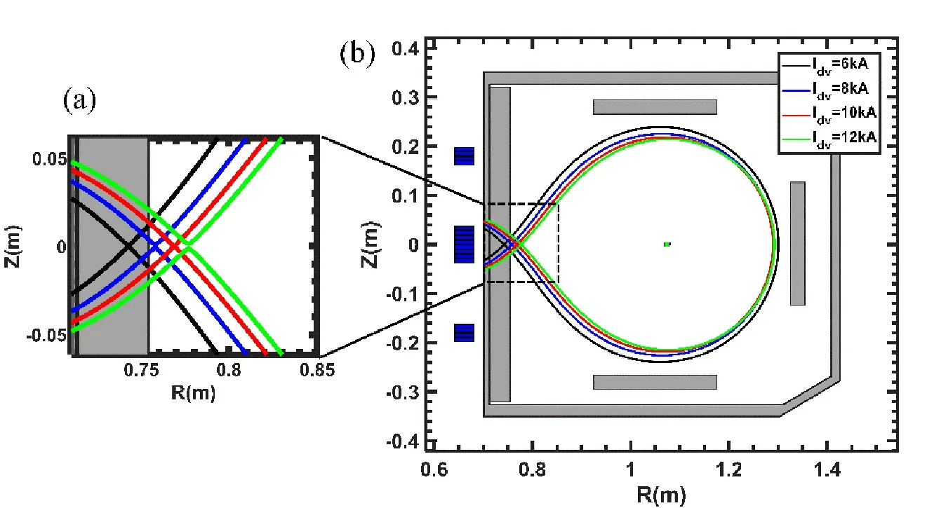
Figure 1.The separatrix under different divertor coils currents.(a) Enlarged view of the target plate area.(b) Overall schematic.
2.2.The island divertor
The island divertor system consisting of six sets of modular saddle coils was recently built on J-TEXT [27].Figure 2 shows the radial component of then= 1 helical mode spectrum calculated with 1 kAt of the island divertor coil current,Iidc.The horizontal and vertical scales in figure 2 are toroidal mode number,m,and the square root of normalized poloidal magnetic flux,.The black dotted curvein fi gure 2 indicates the radial profile of the plasma safety factor,and the black circles indicate the locations of them/n= 1/1,2/1,3/1 and 4/1 rational flux surfaces from left to right.It can be seen that them/n= 3/1 and 4/1 are the dominant components of the magnetic perturbations (MPs) induced by the island divertor coils.In this experiment,them/n= 4/1 island divertor configuration was formed by using this coil system on J-TEXT.
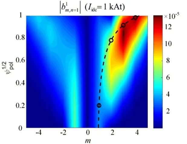
Figure 2.Amplitude distribution diagram of magnetic poloidal mode on the magnetic surface (toroidal mode number n = 1).
Figure 3 shows the time evolution of various plasma parameters in the process of island divertor formation by slowly increasingIidcabove the thresholds that lead to excitations of them/n= 4/1 and 3/1 modes,respectively,on JTEXT.Associated with the formation of them/n= 4/1 island chain att= 0.26 s and them/n= 3/1 island chain att= 0.4 s,respectively,two rapid changes occurred in the radial profile of the plasma perpendicular rotation velocity,V⊥,magnetic fluctuation spectrum and ion saturation current pattern on the divertor plate.When the first rapid change occurs,as indicated by the black vertical dotted line in figure 3,Iidcis about 2 kA.TheV⊥measured by the Doppler backward scattering(DBS) system [28] decreases in all the radial locations,and the rotation atr= 0.255 m near them/n= 4/1 rational flux surface even reverses from the electron diamagnetic direction to the ion diamagnetic direction,as shown in figure 3(b).This illustrates the penetration of them/n= 4/1 field.During the formation of them/n= 4/1 edge islands,the main striking points,indicated by the peak of the ion saturation current distribution measured by the Langmuir probe arrays on the HFS divertor plate,splits into two branches that move in opposite directions away from the mid-plane.
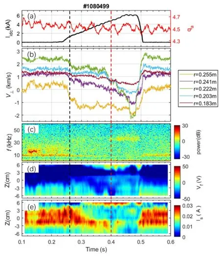
Figure 3.Time evolution of (a) the island divertor coil current Iidc(black line) and the edge safety factor qa (red line),(b) the plasma vertical rotation velocity V⊥,(c) the spectrogram of δBθ from one toroidal Mirnov probe,(d) the contour of the floating potential measured Vf,(e) the contour of the ion saturation current Is from the divertor Langmuir probes during the field penetration experiment.
When the second rapid change occurs att= 0.4 s as indicated by the red vertical dotted line in figure 3,a 35 kHz beta-induced Alfvén eigenmode (BAE) was observed in the spectrogram of poloidal magnetic fluctuation,δBθ,measured by one of the poloidally and toroidally distributed Mirnov coils.In previous J-TEXT experiments,it was often observed that the emergence of this BAE mode was associated with the formation of largem/n= 3/1 islands.In addition,a further modification of the divertor footprints,as well as a rapid reduction in the plasma rotation of the overall confinement region was observed.In particular,theV⊥profile becomes rather flat in between them/n= 3/1 (r~0.222 m) and 4/1 (r~ 0.255 m) rational flux surfaces.All these changes are considered to be due to the formation of them/n= 3/1 and 4/1 edge island chains,and their mutual coupling effects.
Figure 4 shows Poincaré plots and field-line connection length distributions of the plasma edge magnetic island region calculated for six cases with different combinations of threeqa(4.5,4.2,and 3.9) and twoIidc(±4 kA).The calculation results show that a 3D stochastic boundary consisting of them/n= 3/1 and 4/1 remnant magnetic island structures and ergodic fields surrounding them can be formed with the application of RMPs.For the island divertor operation on JTEXT,the field-line connection length distribution in the SOL region is the result of the intersection of the HFS divertor plate with the edge magnetic configuration.Therefore,the 3D edge magnetic structure can be further adjusted by changing the edge safety factor,qa,as well as the amplitude and direction of the island divertor coil current.Asqadecreases,the 4/1 rational flux surface moves outwards,and the degree of openness of the edge island structure caused by the intersection with the divertor plate increases gradually.It should be noted that the plasma response to the RMPs is ignored due to the small pressure gradient and rotation at the edge of the ohmic plasma,and the perturbed magnetic topology is calculated using the vacuum approximation.
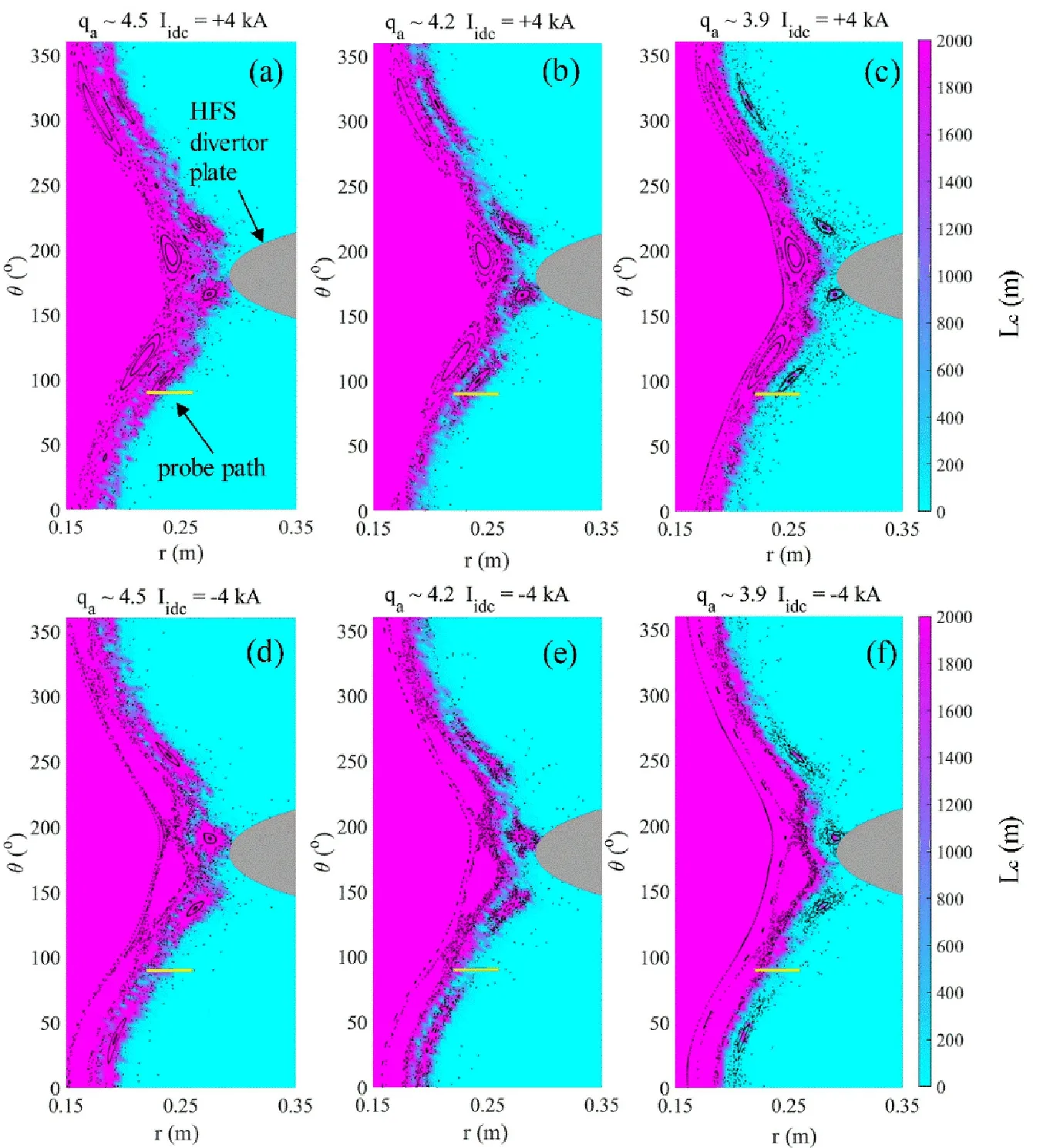
Figure 4.Poincaré plots and field-line connection length distributions of the edge magnetic island region calculated for the plasmas with different edge safety factors (qa) and island divertor coil currents (Iidc).
2.3.RFA probe for the edge ion temperature measurement
On J-TEXT,a multi-channel RFA probe head mounted on the fast-reciprocating manipulator system was used for the edge plasma parameter profile measurements.This manipulator system is located at the upper window of port 12(toroidal angle ϕ=315°) on the device.The path of the RFA probe is plotted with the thick yellow line in figure 4.It can be seen that whenIidc= 4 kA,the probe position is closer to the O-point of them/n= 4/1 island,and closer to the X-point whenIidc= -4 kA.The structure and principle of the RFA probe head are detailed in reference [29].The relationship between the collector current,Ic,and the retarding bias voltage,V2,is as follows:
whereI0is the ion saturation current,Vsis the sheath potential andZis the ion charge number.
One evening Jurgen sat in his room alone: all at once his mindseemed to become clearer, and a restless feeling came over him, suchas had often, in his younger days, driven him out to wander over thesand-hills or on the heath. Home, home! he cried. No one heardhim. He went out and walked towards the dunes. Sand and stones blew into his face, and whirled round him; he went in the direction ofthe church. The sand was banked up the walls, half covering thewindows, but it had been cleared away in front of the door, and theentrance was free and easy to open, so Jurgen went into the church.
During this experiment,the bias voltage on the RFA probe was periodically varied as a 1 kHz sinusoidal function with an amplitude ranging from 0 to 200 V.Figure 5(a)shows an example of the time evolution of theIcand the periodically oscillatingV2for three cycles.The measuredI-Vcharacteristics during these three cycles are plotted in figure 5(b).The ion temperature,Ti,can be obtained by fitting the curve with the piecewise function (1).
This multi-channel RFA probe consists of an RFA and five Langmuir tips arranged at the RFA probe top,which can simultaneously measure information such as ion and electron temperatures.In addition,a combined Langmuirmagnetic probe is installed close to the RFA probe to provide information such as electron temperature and ion saturation current on J-TEXT [30].

Figure 5.(a) The time evolution of the collector current (blue dots)and the biasing voltage (black line).(b) The relationship between collector current and biasing voltage.
3.The SOL τi/e profile in the HFS-MSN poloidal divertor configurations
Figure 6 shows the edge radial distributions of various plasma parameters measured from four HFS-MSN poloidal divertor plasmas with different X-point locations,as described in section 2.2.In the near-SOL region,the electron temperature radially decays from ~ 25 eV to ~ 10 eV,while the ion temperatureTihas no obvious decay and almost remains at 30-40 eV.The difference in electron temperature distribution under differentIdvis small.However,asIdvgradually increases,the maximum gradient region of theTiprofile moves inwards.A similar phenomenon of inward shift is also found in the electron pressure and density profiles.This is consistent with the results obtained from EFIT simulations where the last closed flux surface (LCFS) of the plasma moves inwards with increasingIdv.Theτi/eis in the range of 1-3 and increases with the increase in the minor radius.The radial profiles of thein upstream have been calculated for the plasmas with different X-point positions,as shown in figure 6(g).Theis defined as,and it is roughly varied between 1 and 20.Here,the ion self-collisionality lengths[13].TheLcis the field-line connection length calculated with a field-line tracing code in the near-SOL region,as shown in figure 6(h),and it is less than 30 m for those four discharges,which is about ~ four toroidal turns.ThenuandTiare the local electron density and ion temperature measured by the RFA probe in the SOL upstream,as shown in figures 6(b) and (e).
Figure 7 shows the dependence of various edge plasma parameters on the.As can be seen,the ion temperature gradually decreases with the,while no obvious dependence of the electron temperature and density on the.τi/eis observed to gradually decrease from ~ 5 to ~ 1 when theincreases from ~ 1 to ~ 20.The dependence ofτi/eon theis found to be different in the HFS-MSN poloidal divertor plasmas with different X-point positions.Under the same,theτi/emeasured in the near-SOL region in the HFS-MSN poloidal divertor plasmas decreases as the distance between the X-point and the divertor target increases.
4.The SOL τi/e profile in the island divertor configuration
4.1.τi/e near the X-point and the O-point of the edge remnant island
In order to compare the plasma parameter profiles near the Xpoint and the O-point of the remnant edge islands,an island divertor plasma with the edge safety factorqa= 4.5,similar to that shown in figure 3,was performed,and different island divertor coil currents (Iidc= 0,4,-4 kA) were applied shot by shot.According to the Poincaré plots and the fieldline connection length distribution shown in figures 4(a) and(d),the 4/1 magnetic island chain will be partially scraped by the HFS divertor plate in this configuration.Figure 8 shows the edge profiles of various plasma parameters measured by the RFA probe at differentIidc.Here,the profiles labeledIidc= 0 correspond to the case of the normal limiter configuration (black signal),whileIidc= 4 kA and -4 kA represent the profiles measured near the O-point (red signal) and the Xpoint (blue signal) of them/n= 4/1 remnant island under the island divertor configuration.
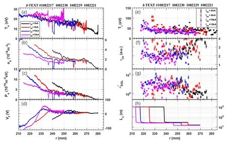
Figure 6.The radial distributions of (a) the electron temperature Te,(b) the electron density ne,(c) the electron pressure Pe,(d) the floating potential Vf,(e) the ion temperature Ti,(f) the ion-to-electron temperature ratio τi/e,(g) the normalized ion collisionality in the upstream SOL,(h) the connection length of the magnetic field lines Lc.
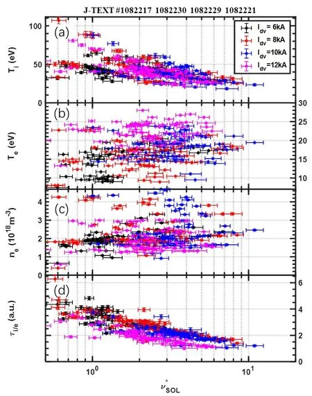
Figure 7.RFA measurement for (a) Ti,(b) Te,(c) ne and (d) τi/e as a function of .
As can be seen,the profiles ofTeandPemeasured in the island divertor configuration are flatter than that in the limiter configuration,which may be due to the formation of a 3D stochastic boundary.BothTiandTemeasured near the O-point are relatively low compared to that measured near the X-point.An ion temperature shoulder is formed with the shoulder edge located radially atr~ 250 mm whenIc=-4 kA,which is near the steep-drop position of the field-line connection length profile.
4.2.Dependence of the SOL τi/e on the edge safety factor in island divertor configuration plasmas
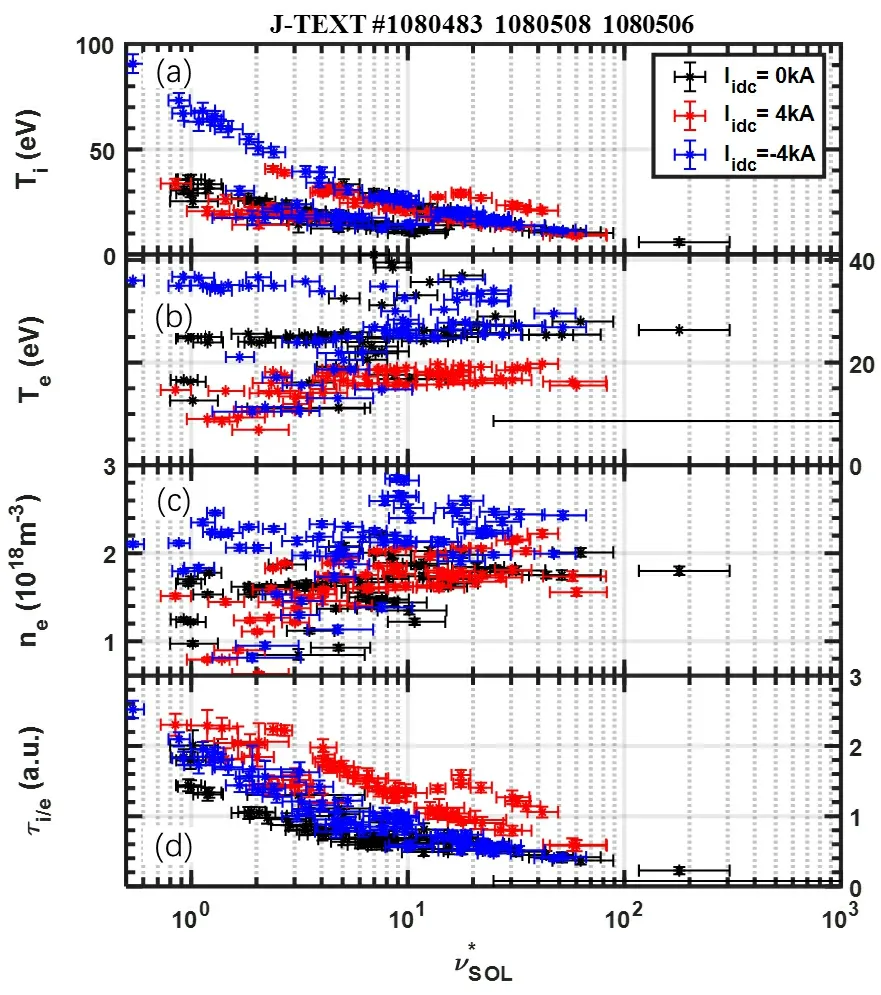
Figure 9.RFA measurement for (a) Ti,(b) Te,(c) ne and (d) τi/e as a function of the .
The edge parameter profiles under magnetic island divertor configurations with different edge safety factors are measured and compared in this section.The extent to which the magnetic island is scraped increases with the increase ofqa.The edge temperatures are quite different near the Opoint and the X-point whenqa= 4.5 as discussed in the previous section.Whenqa= 4.2,the electron temperature difference near the O-point and the X-point becomes smaller,as shown in figure 10.When decreasingqafurther to 3.9,the temperature difference between the O-point and the X-point is basically not obvious since them/n= 4/1 magnetic island is completely intersected with the divertor plate,as shown in figures 4(c) and (f).It should be noted that the field-line connection length in the near-SOL region can be up to a few kilometers in the island divertor configurations,which is two orders of magnitude longer than that in the normal limiter configuration.
The dependence ofτi/eonis changed when the edge magnetic configuration is changed by reducingqa.As can be seen in figure 11,the difference between the dependence near the O-point and the X-point gradually decreases with the decrease ofqa.Whenqa= 4.5,τi/enear the O-point is by a factor of ~ 2 higher than that near the X-point under the same,but they are basically equal whenqa= 3.9.However,the SOLτi/ein the island divertor configuration is still by a factor of ~ 2 higher than that in the normal limiter configuration.
5.Discussion
Previous experiments and simulation results have shown thatτi/edecreases with an increase of the SOL ion self-collisionality,[13].In the complex collision process between ions and electrons,it is generally assumed that the electron-ion collision time is approximately equal to the electron-electron collision time [31].Since the electron selfcollisionality lengthsλeecan be described as λee≈,it is generally not distinguished whetherλeeorλiiis the normalization parameter for the definition of the SOL collisionality [13].In order to better compare with previous research results,we chose the SOL ion self-collisionality as the control parameter to study theτi/ein this paper.
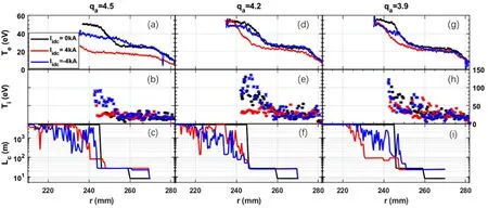
Figure 10.The radial distributions of (a) (d) (g) the electron temperature Te,(b) (e) (h) the ion temperature Ti,(c) (f) (i) the connection length of the magnetic field lines Lc.The three columns of graphs from left to right represent qa = 4.5,4.2 and 3.9 respectively.
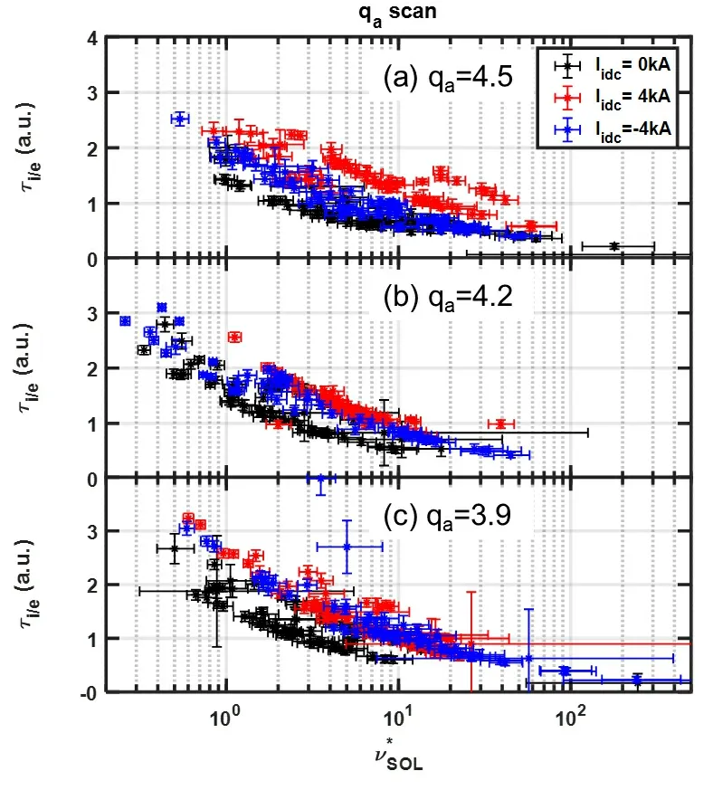
Figure 11.τi/e as a function of with different qa.
Comparison of the dependence ofτi/eonunder various configurations,including the limiter,the HFS-MSN poloidal divertor and the island divertor configurations,has been carried out on J-TEXT.Figure 12 summarizes the plots of theτi/eas a function offor five cases,(i) the limiter configuration withIdv= 6 kA,(ii) the HFS-MSN poloidal divertor configuration,(iii) the island divertor configuration near the O-point,(iv) near the X-point withqa= 4.5 and (v)the standard HFS limiter configuration.
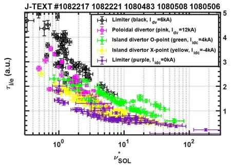
Figure 12.Dependence of τi/e on under different configurations.
In all five cases,τi/edecreases asincreases.For the limiter configuration,when there is a 6 kA poloidal divertor coil current,compared with the normal HFS limiter configuration,the gradient ofτi/ewith theis larger and the value ofτi/eis higher.For the island divertor configuration,theτi/enear the O-point of island divertor configuration is larger than that near the X-point under the same,and theτi/eof the HFS-MSN poloidal divertor configuration is between these two.
The results show that the dependence of the edge ion-electron temperature ratio on theunder different configurations is different.The experimental observations demonstrated that the SOLτi/eis not only related to.The edge neutral and impurity transport due to configuration changes should also be taken into account.Further analysis requires simulation of the transport process by a threedimensional edge transport code,such as EMC3-EIRENE.
6.Conclusion
In this paper,the characteristics of the SOL plasma parameters under various magnetic configurations of the limiter,HFS-MSN poloidal divertor and island divertor have been observed by using a new multi-channel RFA probe head on the J-TEXT tokamak.In the HFS-MSN poloidal divertor configuration,the experimental observations show a decrease in theτi/eunder the sameas the X-point moves away from the divertor target plate.τi/eis observed to gradually decrease from ~ 5 to ~ 1 asincreases from ~ 1 to ~20.In the island divertor configuration,the SOL plasma parameter profile was measured for different magnetic configurations by either varying the edge safety factor or reversing the phase of the edge magnetic islands.τi/eis observed to gradually decrease from ~ 2.5 to ~ 0.5 asincreases from ~ 1 to ~ 100.τi/enear the O-point is higher than that near the X-point under the same.However,asqaincreases,the more the edgem/n= 4/1 magnetic islands are scraped off,the difference gradually decreases.The experimental results demonstrate that the dependence of the SOLτi/eon theunder different configurations was found to be different.
Acknowledgments
The authors are very grateful for the help of the J-TEXT team.This work is supported by the National Magnetic Confinement Fusion Energy R&D Program of China (No.2018YFE0309100) and National Natural Science Foundation of China (No.51821005).
杂志排行
Plasma Science and Technology的其它文章
- Detection of Al,Mg,Ca,and Zn in copper slag by LIBS combined with calibration curve and PLSR methods
- Experimental study on the effect of H2O and O2 on the degradation of SF6 by pulsed dielectric barrier discharge
- Phase field model for electric-thermal coupled discharge breakdown of polyimide nanocomposites under high frequency electrical stress
- Non-thermal atmospheric-pressure positive pulsating corona discharge in degradation of textile dye Reactive Blue 19 enhanced by Bi2O3 catalyst
- Airfoil friction drag reduction based on grid-type and super-dense array plasma actuators
- Characteristics of laser-induced breakdown spectroscopy of liquid slag
