RRT Autonomous Detection Algorithm Based on Multiple Pilot Point Bias Strategy and Karto SLAM Algorithm
2024-03-13LiepingZhangXiaoxuShiLiuTangYilinWangJianshengPengandJianchuZou
Lieping Zhang ,Xiaoxu Shi ,Liu Tang ,Yilin Wang ,Jiansheng Peng and Jianchu Zou,⋆
1Key Laboratory of Advanced Manufacturing and Automation Technology(Guilin University of Technology),Education Department of Guangxi Zhuang Autonomous Region,Guilin,541006,China
2College of Mechanical and Control Engineering,Guilin University of Technology,Guilin,541006,China
3Guilin Mingfu Robot Technology Company Limited,Guilin,541199,China
4Key Laboratory of AI and Information Processing(Hechi University),Education Department of Guangxi Zhuang Autonomous Region,Yizhou,546300,China
ABSTRACT A Rapid-exploration Random Tree (RRT) autonomous detection algorithm based on the multi-guide-node deflection strategy and Karto Simultaneous Localization and Mapping(SLAM)algorithm was proposed to solve the problems of low efficiency of detecting frontier boundary points and drift distortion in the process of map building in the traditional RRT algorithm in the autonomous detection strategy of mobile robot.Firstly,an RRT global frontier boundary point detection algorithm based on the multi-guide-node deflection strategy was put forward,which introduces the reference value of guide nodes’ deflection probability into the random sampling function so that the global search tree can detect frontier boundary points towards the guide nodes according to random probability.After that,a new autonomous detection algorithm for mobile robots was proposed by combining the graph optimization-based Karto SLAM algorithm with the previously improved RRT algorithm.The algorithm simulation platform based on the Gazebo platform was built.The simulation results show that compared with the traditional RRT algorithm,the proposed RRT autonomous detection algorithm can effectively reduce the time of autonomous detection,plan the length of detection trajectory under the condition of high average detection coverage,and complete the task of autonomous detection mapping more efficiently.Finally,with the help of the ROS-based mobile robot experimental platform,the performance of the proposed algorithm was verified in the real environment of different obstacles.The experimental results show that in the actual environment of simple and complex obstacles,the proposed RRT autonomous detection algorithm was superior to the traditional RRT autonomous detection algorithm in the time of detection,length of detection trajectory,and average coverage,thus improving the efficiency and accuracy of autonomous detection.
KEYWORDS Autonomous detection;RRT algorithm;mobile robot;ROS;Karto SLAM algorithm
1 Introduction
The mobile robot is a kind of comprehensive system integrating environment sensing,dynamic decision-making,behavioral control,and other multi-functions,obtaining the surrounding environment information through the sensors it carries,such as light detection and ranging (LIDAR),camera rangefinder,infrared,and so on,to complete specific functions according to the designer’s requirements automatically.It has already achieved various applications in various fields,such as industry,agriculture,and military[1].
Autonomous detection by mobile robots plays an indispensable role in various types of applications,such as environmental monitoring,intelligent agriculture,search and rescue,and resource exploration.However,the lack of a priori information about the surrounding environment and the limited sensing range of self-loaded sensors increase the difficulty of making optimal decisions in the detection process.Constrained by the endurance of robots and the urgency of tasks(e.g.,in disaster relief environments),there is an urgent need for methods to drive robots to complete environmental exploration rapidly.
Autonomous exploration of mobile robots refers to the mobile robot,without human intervention,autonomously in an unknown environment to select the target point to explore and build the map,and finally build a complete indoor map[2].Autonomous exploration is a crucial step for robots to realize genuine autonomy,which is an important research direction in robotics.The core problem of autonomous exploration is how to complete the traversal of the environment where the mobile robot is located in a short time and distance to get enough spatial environment for global map creation,which is the core problem of autonomous exploration[3].Robots’autonomous environmental exploration strategies are mainly divided into two categories: autonomous exploration based on the boundary theory and autonomous exploration based on random sampling.
The boundary-based exploration algorithm was first proposed by Yamauchi et al.[4].The method explained the exploration problem of unknown environments as how to use the known spatial environmental information to acquire more unknown spatial environmental information.The main idea of this method is described as follows: a guide node is established at the junction between the explored space and the unexplored space,which guides robots to move towards its direction.However,the boundary points extracted by the algorithm may not guarantee the acquisition of new environmental information but may increase the search path of mobile robots.For this reason,an evaluation index for boundary points referred to as the Next Best View(NBV)has been added by many scholars.Liu et al.[5] combined NBV sampling with boundary exploration to generate a node tree representing the robot NBV for the robot to follow,thereby reducing the complexity of the algorithm and optimizing the exploration efficiency.Senarathne et al.[6]proposed a computationally efficient incremental boundary detection method that reduces the computational effort of the boundary generation algorithm while improving the execution efficiency.Most of the autonomous detections based on boundary theory are based on image processing such as edge detection,so it also limits its application to the two-dimensional plane.Meanwhile,to extract the detection boundary,it is necessary to traverse the entire map.Therefore,as the map continues to expand,the computational resources it consumes also increase[7].
A typical representative of random sampling-based autonomous detection methods is the Rapidly-exploration Random Trees(RRT)algorithm[8].The RRT algorithm takes the starting point as the root node of the expanding tree and adopts a random sampling method for the expansion of the leaf nodes until the endpoint,or the region in which the endpoint is located,is included in the leaf nodes.As the growth process of the random tree of the RRT algorithm itself is random,it will cause the robot to repeatedly detect the same region,resulting in the loss of the advantage of maximizing the gain obtained from the motion by searching the boundaries,which is the advantage of the boundary search-based detection method,thus reducing the overall efficiency of the detection[9].To address the shortcomings of the RRT algorithm,researchers have proposed many improved algorithms.Umari et al.[10]proposed a new Rapid-exploration Random Tree(RRT)-based boundary exploration method by combining boundary exploration with RRT random exploration.Instead of using image processing to extract boundaries,the proposed algorithm uses the RRT algorithm to acquire boundary points rapidly and guide robots toward such boundary points to improve exploration efficiency.Zeng et al.[11]proposed an autonomous mobile robot exploration algorithm based on sparse and relatively small-sized local maps of point clouds.The algorithm utilized the RRT algorithm to detect the boundary and plan the local path on the unordered local maps of point clouds.Chen et al.[12]proposed an Intelligent Rapidly-exploring Random Tree(IRRT)algorithm based on evolutionary cognition.The algorithm intelligently adjusts the growth rate of the global search tree according to the complete situation of the exploration map,filters the detected boundary points using a spatial clustering algorithm through density-based noise,and acquires the current target point set that guides the robot to move.Xu et al.[13] came up with a hybrid frontier detection strategy for autonomous exploration,which combined a variable-step-size random tree global frontier detector,a multi-root-node random tree boundary detector,and a grid-based frontier detection algorithm,enabling the robot to search the boundary in real time quickly and effectively solving the autonomous exploration problem in a multi-obstacle environment with a narrow entrance.Sumer et al.[14]searched the existing maps and detected boundary points via an RRT tree structure based on permanence and temporality.The permanent tree takes root from the initial position of the robot and will never be reset.Therein,the temporary tree will be reset when reaching the boundary point or reaching a certain number of branches.Duberg et al.[15]put forward an exploration method of map-driven updating,which updated and expanded the planning structure based on dense maps every time the map was updated.
Li et al.[16]put forward a compound candidate target point detection strategy that implemented RRT and frontier method collaboratively,ensured that robots could smoothly reach the target point by designing an improved Time Elastic Band(TEB)with the cost calculation method as the evaluation criterion for the optimal candidate target point,and effectively solved the exploration difficulty of robots in an open hall environment.Ruan et al.[17]put forward a robot environmental exploration strategy integrating information gain and RRT.This strategy estimates the information of the nodes in the unknown environment,selects the node with the largest information gain as the sampling node,and generates new nodes with the largest information gain for expansion,thus reducing the blindness of exploration.Besides,Qi et al.[18]discovered the boundary of maps by using a variable-growth-rate local and RRT global algorithm as the detector,clustered frontier points to improve the autonomous exploration efficiency of robots.
From the above analysis,it can be seen that in the current studies on autonomous exploration strategies based on random sampling,due to the random nature of the random tree growth process of the RRT algorithm,there is the problem of not being able to maximize the obtained information about the unknown environment by searching for the frontier,which affects the convergence of the algorithm.At the same time,combining the RRT frontier detection algorithm with other search strategies speeds up the autonomous exploration of robots,but no requirements have been proposed for the autonomous exploration results of robots,accompanied by drift distortion.Therefore,an indepth investigation of the efficient exploration problem was of great significance and urgent need.In this paper,we proposed an RRT autonomous detection algorithm based on the multi-pilot point bias strategy and Karto Simultaneous Localization and Mapping (SLAM) algorithm.We carried out research and experimental analysis on the autonomous detection method to form a solution for the autonomous detection of mobile robots,to enable mobile robots to realize efficient detection of unknown environments,which was important for promoting the degree of intelligence of mobile robots and the industrialization of mobile robots.It was important for promoting the degree of intelligence of mobile robots and the development of their automation.The contributions of this study were summarized as follows:
(1) To improve the detection efficiency of the traditional RRT algorithm for frontier boundary points,a random sampling function of the multi-guide-node deflection strategy was introduced to improve the convergence performance of the RRT global frontier boundary point detection algorithm.
(2) Aiming at the problem of drift distortion due to the dependence on odometry during the traditional RRT autonomous detection strategy,the Karto SLAM algorithm was introduced and combined with the improved RRT global frontier boundary point detection algorithm into a new autonomous detection strategy,which improved the autonomous detection efficiency and accuracy of autonomous mobile robots.
The remainder of this paper was structured as follows:the RRT algorithm and improvement of autonomous detection strategy are described in Section 2.The improved RRT algorithm and SLAM algorithm fusion for the autonomous detection algorithm of mobile robots are explained in detail in Section 3.Section 4 verifies and analyzes the performance of the autonomous detection principle of the proposed RRT algorithm by designing simulation experiments and real experiments.The conclusion is presented in Section 5.
2 RRT Algorithm and Improvement for Autonomous Detection Strategy
2.1 RRT Global Frontier Boundary Point Detection Algorithm
The Traditional RRT algorithm had the characteristic of actively exploring the unknown space,and the iteratively generated search tree branches can completely cover the unknown regions in the whole detection space with the extension of time.Still,the active detection efficiency of mobile robots using the RRT algorithm is not high [19].Since the branches of the random search tree grow from the random sampling point at any different time,mobile robots tend to repeatedly explore the known region in the process of active detection,which seriously affects the active detection efficiency [20].Considering the map overlapping problem in active detection,Umari et al.[21]proposed a new strategy to quickly detect frontier boundary points by the RRT algorithm.For this new strategy,the search branches generated by the RRT algorithm no longer guide the active detection direction of the mobile robot,and they are only used to search frontier boundary points.The frontier boundary points,when found by the RRT algorithm,will be collected,filtered,and distributed to the mobile robot in sequence.After receiving the frontier boundary points,the mobile robot will set the frontier boundary points as the path-planning target points and move toward them through a path-planning algorithm.While moving towards the frontier boundary points,the mobile robot adopts the matched detection sensor to scan and explore the adjacent region within the scanning range of the sensor,thus constantly searching for new frontier boundary points.Meanwhile,the set of frontier boundary points is updated to expand the known region occupied by the grid map.The frontier boundary point retrieval part of the proposed algorithm is composed of a local frontier boundary point detection part and a global frontier boundary point detection part.In this paper,we improved on the RRT global frontier boundary point detection strategy.The RRT global frontier boundary point detection process is shown in Fig.1.
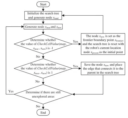
Figure 1:Flowchart of RRT global frontier boundary point detection
In Fig.1,xrandis the random sampling point generated by the random sampling functionSampleNode(),xnearstands for the node selected on the random search tree and shows the closest Euclidean distance to the random sampling pointxrand,andxnewrepresents a new node extending toward the random sampling pointxrandwithxnearas the parent node.
2.2 RRT Global Frontier Boundary Point Detection Algorithm Based on Multi-Guide-Node Deflection Strategy
Based on the previously described global frontier boundary point detection method,a random sampling function based on the multi-pilot deflection bias strategy was proposed.The improved RRT algorithm introduced the reference valueGuideprobfor the deflection probability of guide nodes,which utilized the feedback information of the previous search to guide the nodes toward the target point sampling during the search process,avoided the blind search of the random tree,and reduced the ineffective nodes,improved the convergence performance of the global frontier boundary point detection algorithm of RRT,and further improved the efficiency of the global search tree in detecting the frontier boundary points.The flowchart of the random sampling function based on the multiguide-node deflection strategy is shown in Fig.2,and the specific random sampling process is as follows:
Step 1: When the function starts running,a random real number within [0,1] is generated and assigned to the probabilityp.The value of the labeliis a random real number in[-1,0].
Step 2:The probabilitypis judged.Ifpis greater than 0 and less than or equal to the reference valueGuideprobfor the deflection probability of guide nodes,the random sampling pointxrandis set as the node of the corresponding labeliin the guide node cache set.If the guide node cache setGuideNodeCacheis empty,the algorithm is being initialized or random extension has not begun yet,and the random sampling point is generated by the random sampling functionSampleNode().
Step 3: If the probabilitypis greater thanGuideproband less than or equal to 1,the random sampling pointxrandis randomly generated in the finite state space by the random sampling functionSampleNode()in the basic RRT algorithm.
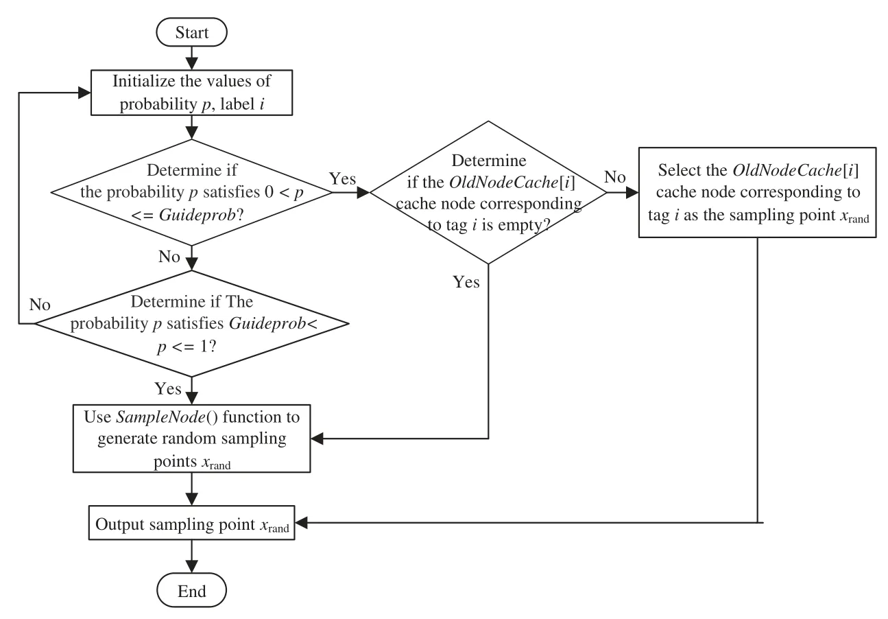
Figure 2:Flowchart of the random sampling function based on the multi-guide-node deflection strategy
3 Autonomous Detection Algorithm for Mobile Robots Combining Improved RRT Algorithm and Karto SLAM Algorithm
3.1 Karto SLAM Algorithm
SLAM is the premise for the path planning of mobile robots and also the information base for their autonomous navigation.When it comes to SLAM technology,a robot,that is located in an unknown region with its initial position completely unknown,perceives the surrounding environment through its built-in sensors,and the current position of the robot is determined based on the information data it collects.Then,the current position of the robot is judged and the unknown region is mapped with its movement in the unknown region.According to the types of sensors configured by the robot itself,the methods to solve the SLAM problem can be divided into Lidar SLAM and Visual SLAM[22].The mobile robot used in this study was matched with a lidar.Generally,SLAM is implemented using two-dimensional lidar SLAM methods like the Gmapping algorithm,Hector SLAM algorithm,and Cartographer algorithm[23].In the autonomous exploration of mobile robots proposed by Hassan Umari,the SLAM problem is solved using the Gmapping algorithm,which,however,heavily relies upon odometers and is very prone to drift distortion.
The framework of the Karto SLAM algorithm,a graph optimization-based SLAM algorithm,consists of the front end and the rear end,as shown in Fig.3[24].Therein,the front end takes charge of scan matching,providing the estimated position and posture,and building the map in the form of pictures.The rear end is responsible for nonlinear global optimization and eliminates the cumulative error generated when the robot passes through the same position repeatedly.Closed loop detection means that the robot finds its position in the process of scan matching,which provides constraints for the rear-end nonlinear global optimization.
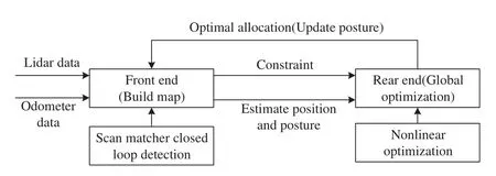
Figure 3:Karto SLAM algorithm framework
In the Karto SLAM algorithm,the rear-end framework is optimized by Sparse Pose Adjustment(SPA),that is,a graph is used to represent the historical measurement results of the robot,and each node on the graph stands for the pose calculated by Correlative Scan Matching(CSM),and the spatial constraint from one measurement nodeaito another nodeajis represented by the edge between two nodes[25].In the structure ofai,the measured offset of nodesaiandajis denoted as.The variableaican be parameterized by a translation vectortiand a rotation angleθi,whereti=[xi,yi]Trepresents the specific position of the robot andθistands for the rotation angle of the robot at timei,i=1,2,...,T.For any two measurement nodesaiandaj,their measured offset can be calculated by the following formula:
In formula(1),h(ai,aj)represents the predicted observation value,andRiis a 2×2 rotation matrix,which is represented byθias seen in formula(2).
On this basis,the error functioneijrelated to the spatial constraint can be obtained,as shown in formula(3).
The total errorJ2(a)can be calculated by formula(4).
In formula(4),the information matrixΩijis the inverse of the covariance matrix between the measurement nodesaiandaj.The total error in formula(4) was minimized using the Levenberg-Marquardt(LM)optimization algorithm to eliminate the cumulative error and determine the position and posture of the robot.After obtaining the pose of the robot,the environmental map around the robot was built through the front end and solved through such optimization libraries as G2O and Ceres,and finally,the SLAM problem was solved[26].The Gmapping algorithm had only the frontend part,which used radar data for scanning matching and map building 2 functions.The Karto SLAM algorithm introduced the back-end optimization and loopback detection into the Lidar SLAM to reduce the cumulative error through the optimization of the bitmap structure and build a map with better effect,so this paper used the Karto SLAM algorithm to solve the SLAM problem.
3.2 Mobile Autonomous Detection Algorithm Based on Improved RRT Algorithm and Karto SLAM Algorithm
The primary purpose of active detection by a mobile robot is to extend the portion of the map that the mobile robot has already reached and detected by guiding its movement into the unknown surrounding area through the detection algorithms and creating a map of the environment through which it passes.Active detection by mobile robots generally employs a detection strategy that continually moves toward the front boundary of the map.Frontier boundaries are lines separating known and unknown spaces in the occupied raster map.When a mobile robot detects a specific frontier boundary line,the center of mass on this frontier boundary line is selected to guide the robot toward the frontier boundary.
In this paper,we proposed a novel RRT algorithm for active detection strategy,which used the Karto SLAM algorithm based on graph optimization for simultaneous localization and map construction to improve the accuracy of autonomous exploration results effectively.Meanwhile,the Karto SLAM algorithm was combined with the previously proposed RRT global frontier boundary point detection algorithm to form the mobile robot autonomous exploration RRT algorithm in this paper.The autonomous exploration framework proposed in this paper is shown in Fig.4.
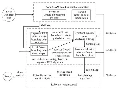
Figure 4:This paper proposes a framework for autonomous detection of mobile robots
The proposed RRT active detection strategy consists of a local frontier boundary point detection part and an improved RRT global frontier boundary point detection part.After receiving the frontier boundary points,the proposed strategy collects all of them and stores them in the frontier boundary point collection.To control the number of frontier boundary points,the algorithm uses a clustering algorithm to perform a clustering operation on the points in the collection of frontier boundary points,except for the center frontier boundary point of each class group,all the rest of the frontier boundary points are discarded and not saved,and during each iteration of the processing,the frontier boundary points that have been invalidated and detected are deleted,and the rest of the frontier boundary points are saved and released.After receiving the frontier boundary points after the clustering and filtering process,the proposed algorithm calculates the assigned frontier boundary point gain for each frontier boundary point,and the point with the highest assigned frontier boundary point gain is set as the frontier boundary point that the mobile robot will detect autonomously.
4 Experimental Validation and Result Analysis
4.1 Simulation Experiment
4.1.1 Experimental Environmental Design
The operating system of this experiment was Linux equipped with Intel(R)Core(TM)i5-2430M CPU,4 GB memory,Intel(R)HD Graphics 3000 graphics card,Ubuntu 16.04,simulation platform Gazebo,and visualization tool RViz.To explore the effect of the improved RRT autonomous detection strategy proposed in this study in different three-dimensional simulation spaces,an environment with fewer obstacles and an environment with complex obstacles were designed.Meanwhile,the latter environment was enabled to accommodate enough obstacles and the former one was enabled to test the detection effect of the improved RRT autonomous detection strategy in an open environment.In this experiment,two three-dimensional simulation spaces were built on the Gazebo platform,namely,one 17×15 m2space with fewer obstacles and one 15×12 m2space with complex obstacles.Every obstacle environment was surrounded by red bricks,and the free space was divided by yellow wooden walls.In the environment with fewer obstacles,there were only two green garbage bins and a big white square,while the other environment was full of obstacles of different types and sizes.In this experiment,the growth rateηof the search tree in autonomous detection represents the extension step length of the random search tree and reflects its detection efficiency.According to [27],the parameters of different simulation environments were adjusted.The following constants and variables were set for the autonomous detection of the mobile robot: the model size of the mobile robot was 0.35 m×0.4 m×0.5 m,the maximum linear velocity was 0.3 m/s,the maximum angular velocity was 0.5 rad/s,the maximum linear acceleration was 0.5 m/s,the maximum angular acceleration was 1 rad/s,the maximum measuring distance of the lidar was 12 m,and the accuracy of the free-passage map of the robot was 0.01 m.To keep the safe distance between the mobile robot and the obstacle,the expansion radius of the cost map was larger than the width of the robot,which was set to 0.55 m in this study.
4.1.2 Simulation Experiment and Result Analysis
In this autonomous mapping simulation experiment of a mobile robot,the performance of the autonomous exploration strategy integrating Gmapping with the traditional RRT algorithm was proposed in the reference [21] and compared with that of the autonomous exploration strategy combining the Karto SLAM algorithm and the improved RRT algorithm proposed in this study in two different three-dimensional simulation environments.
(1)Experimental environment 1:Three-dimensional simulation environment with fewer obstacles
The growth rateηgof the global random search tree was 20 and that (ηl) of the local random search tree was 7.The mobile robot was initially located at the central point of the three-dimensional simulation environment,as shown in Fig.5a.Exploration and mapping were performed using two different autonomous detection strategies under experimental environment 1.The operation effects of the exploration starting on the Gazebo and RViz platforms are shown in Figs.5a and 5b,respectively.The operation effects of the exploration process on the Gazebo and RViz platforms are shown in Figs.5c and 5d,respectively.The operation effects of the exploration ending on the Gazebo and RViz platforms are shown in Figs.5e and 5f,respectively.
The mapping results of the traditional RRT autonomous exploration strategy are shown in Fig.6,and the mapping results of the autonomous exploration strategy combining the Karto SLAM algorithm and the improved RRT algorithm proposed in this study are displayed in Fig.7.
It could be intuitively observed from Figs.6 and 7 that a small amount of remnant drifting trace was found on the wall surface as reflected in the detection result of the traditional RRT autonomous exploration strategy,but the overall difference in the mapping effect between the two autonomous exploration strategies was unobvious.To judge the detection effect of the two strategies more accurately,the measured value and map-measured value were compared at a total of 10 positions using the projected lengths of obstacles such as brick walls,wooden walls,and garbage cans on the ground in the simulation space.In experimental environment 1,the mapping errors of the traditional and improved RRT autonomous exploration strategies are presented in Tables 1 and 2,respectively.A comparison of the relative errors of the detection results of the two different autonomous detection algorithms is shown in Fig.8.
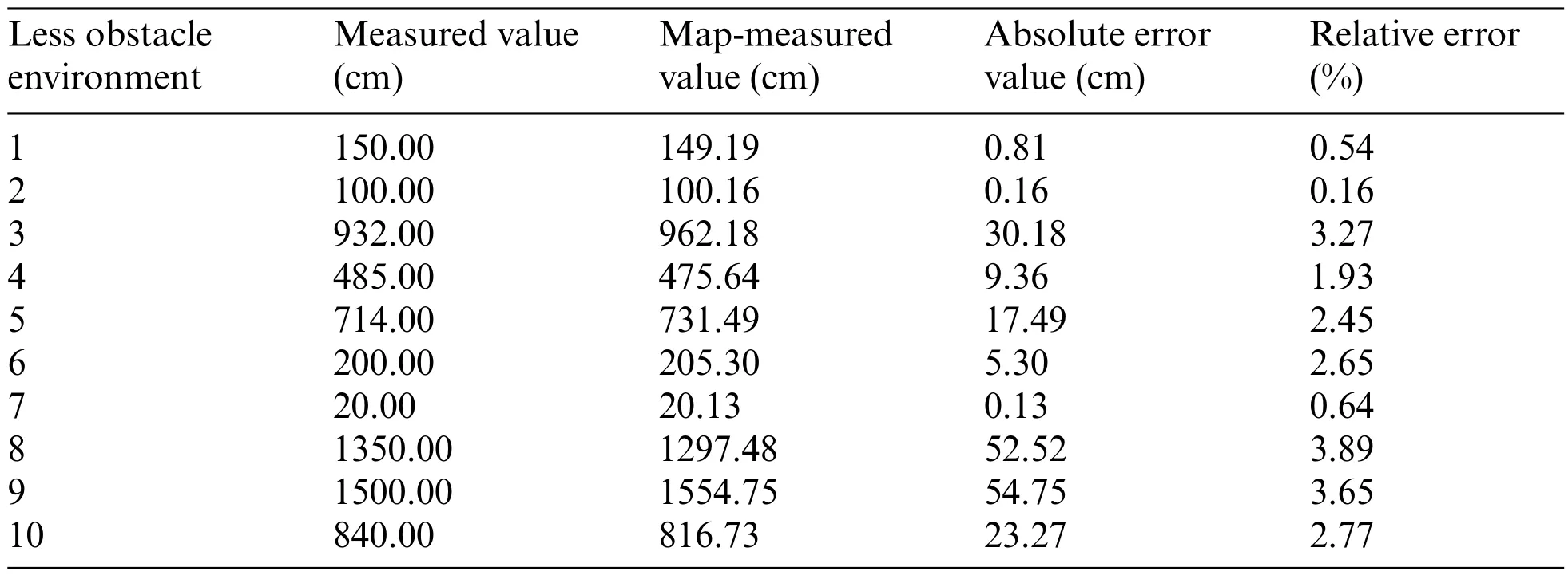
Table 1:Mapping errors of the traditional RRT autonomous exploration algorithm in experimental environment 1(10 positions)
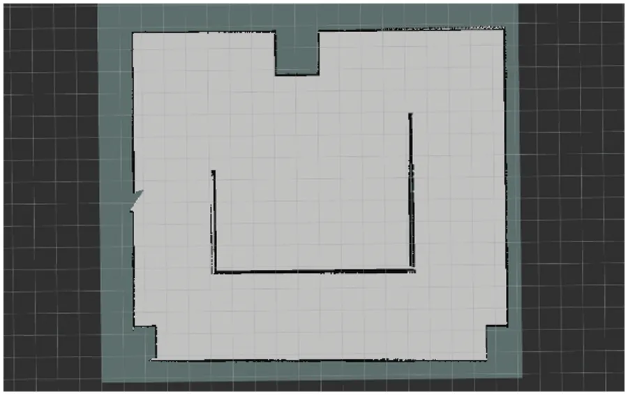
Figure 6:Mapping results of the traditional RRT autonomous exploration strategy in experimental environment 1
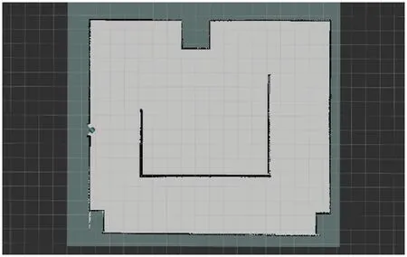
Figure 7:Mapping results of the RRT autonomous detection algorithm proposed in this paper in experimental environment 1
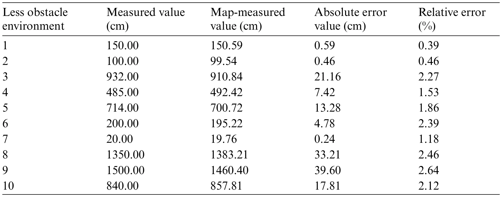
Table 2:Mapping errors of the RRT autonomous detection algorithm proposed in this paper in experimental environment 1(10 positions)
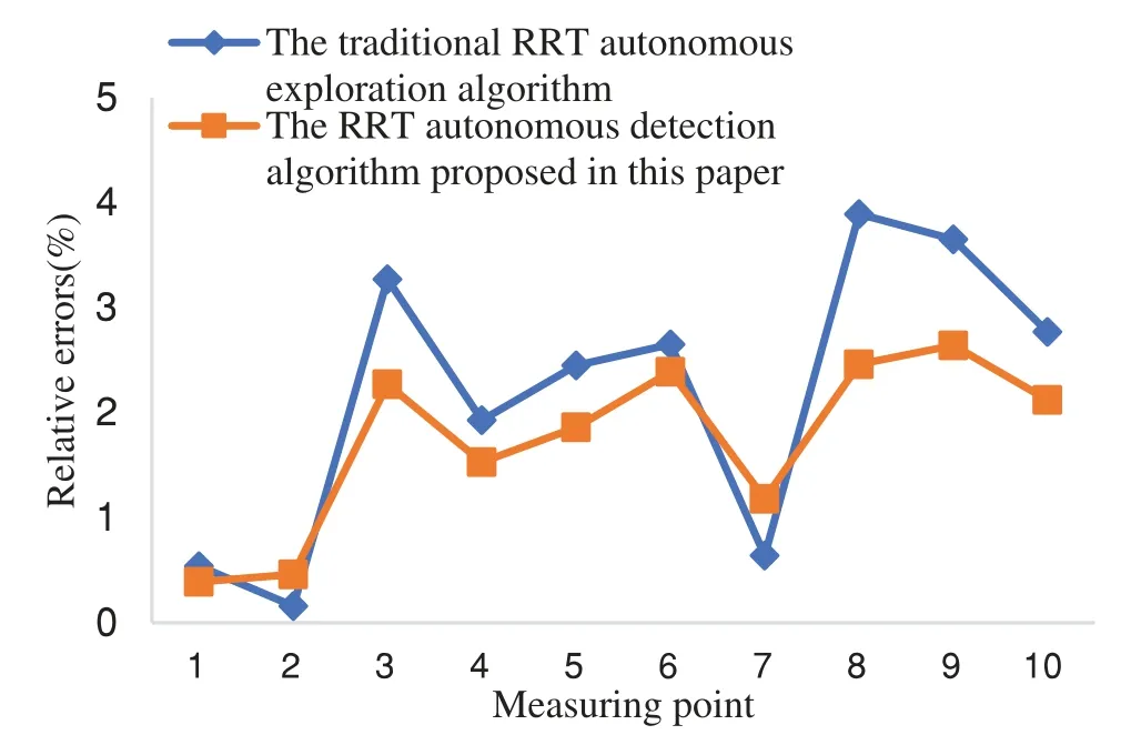
Figure 8:Comparison of the relative errors of the detection results of two different autonomous detection algorithms in experimental environment 1
From Tables 1,2,and Fig.8,it could be seen that the traditional RRT autonomous detection algorithm worked better for small obstacles such as garbage bins in the less obstacle three-dimensional simulation space.However,the RRT autonomous detection algorithm proposed in this paper had little difference compared to it,and the relative error was 0.3%to 0.5%more.For large obstacles such as brick walls,the RRT autonomous detection strategy proposed in this paper was better optimized,with 1%to 1.4%less relative error than the traditional RRT autonomous detection algorithm.
In this study,the index values,such as autonomous detection time,exploration trajectory length,and coverage rate of autonomous detection,of the two different autonomous exploration strategies after operating 5 times in experimental environment 1 were also recorded,as seen in Tables 3 and 4,respectively,and the values were averaged and performance was compared,as shown in Fig.9.
From Tables 3,4,and Fig.9,it could be known that in the three-dimensional simulation space with fewer obstacles,the gap between the two autonomous detection algorithms in the average coverage rate of exploration results was small,both reaching over 92%.However,the RRT autonomous detection algorithm proposed in this paper spent less autonomous detection time,being 19.6 s shorter than that spent by the other strategy.Meanwhile,the average exploration planning trajectory length was also shorter than that of the traditional RRT autonomous exploration algorithm,with a decrease of 15.4 m.Overall,the RRT autonomous detection algorithm proposed in this paper performed better than the traditional RRT autonomous exploration algorithm.

Table 3:Simulation results of the traditional RRT autonomous exploration algorithm in experimental environment 1(5 times)

Table 4:Simulation results of the RRT autonomous detection algorithm proposed in this paper in an experimental environment 1(5 times)

Figure 9:A comparison chart of average exploration performance indexes between two different autonomous detection algorithms in experimental environment 1
(2) Experimental environment 2: three-dimensional simulation environment with complex obstacles
The growth rateηgof the global random search tree was 40 and that (ηl) of the local random search tree was 5.The mobile robot was initially located at the central point of the three-dimensional simulation environment,as shown in Fig.10a.Exploration and mapping were performed using the two different autonomous detection strategies under experimental environment 2.The operation effects of the exploration starting on the Gazebo and RViz platforms are shown in Figs.10a and 10b,respectively.The operation effects of the exploration process on the Gazebo and RViz platforms are shown in Figs.10c and 10d,respectively.The operation effects of the exploration ending on the Gazebo and RViz platforms are shown in Figs.10e and 10f,respectively.
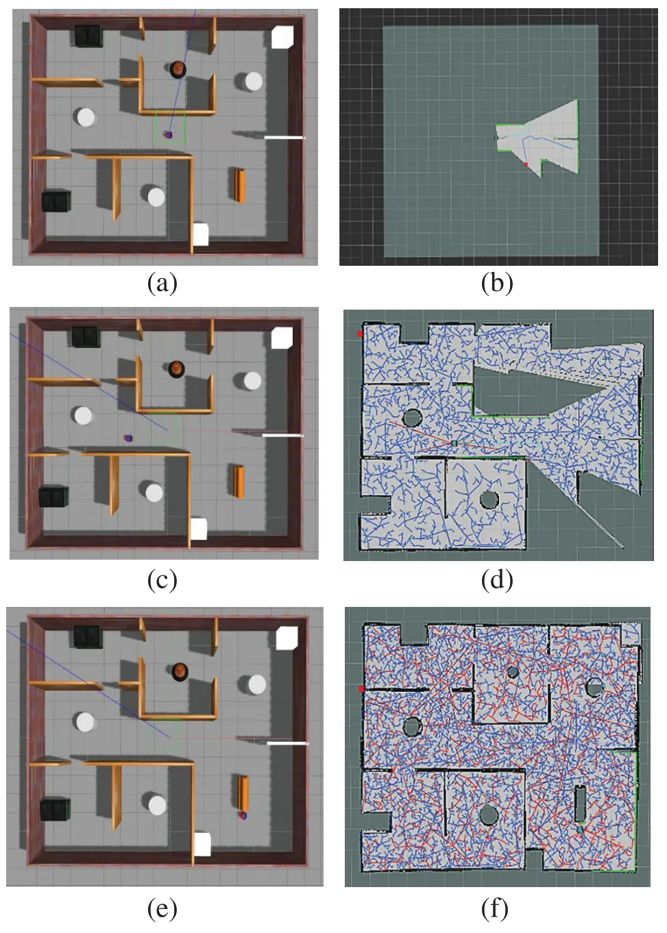
Figure 10:Autonomous exploration simulation diagram of the mobile robot under experimental environment 2.(a)Gazebo exploration starting;(b)RViz exploration starting;(c)Gazebo exploration process;(d)RViz exploration process;(e)Gazebo exploration ending;(f)RViz exploration ending
The mapping results of the traditional RRT autonomous exploration algorithm are shown in Fig.11.The mapping results of the RRT autonomous detection algorithm proposed in this paper are displayed in Fig.12.
From Figs.11 and 12,serious drifting distortion could be observed on walls in the detection results of the traditional RRT autonomous exploration algorithm.The results acquired by the RRT autonomous detection algorithm proposed in this paper differed little from the simulation environment,indicating that the simulation environment could be relatively accurately expressed by the proposed method.To judge the detection effects of the two strategies more accurately,the measured value and map-measured value were compared at a total of 10 positions using the projected lengths of obstacles on the ground such as cylinders,rectangular obstacles,and wooden walls in the simulation space.In experimental environment 2,the mapping errors of the traditional and improved RRT autonomous detection algorithms are listed in Tables 5 and 6,respectively.A comparison of the relative errors of the detection results of the two different autonomous detection algorithms is shown in Fig.13.

Table 5:Mapping errors of the traditional RRT autonomous exploration algorithm in experimental environment 2(10 positions)
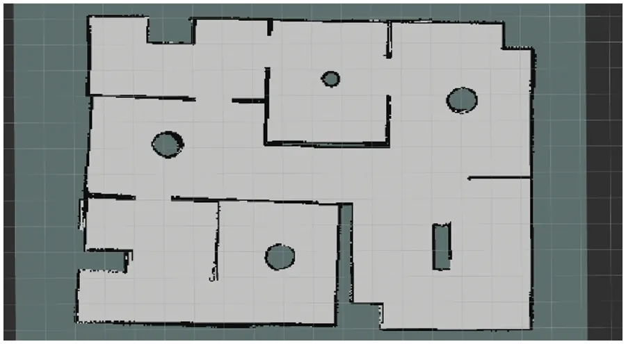
Figure 11:Mapping results of the traditional RRT autonomous exploration algorithm in experimental environment 2
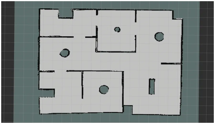
Figure 12:Mapping results of the RRT autonomous detection algorithm proposed in this paper in experimental environment 2
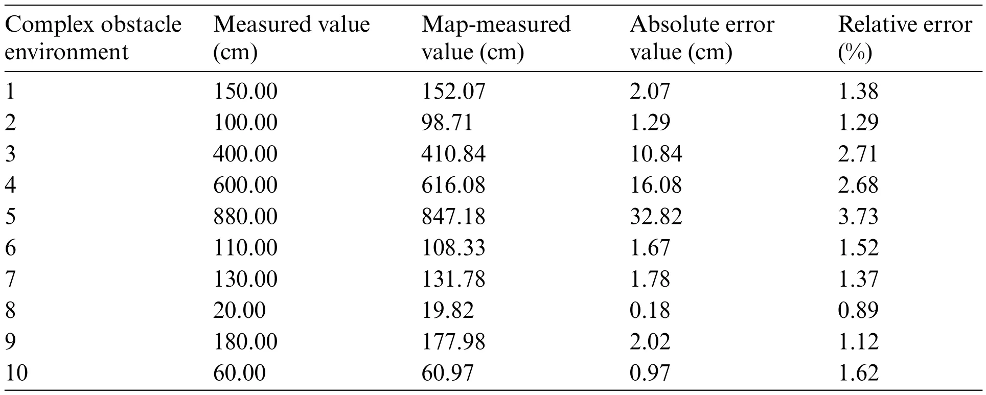
Table 6:Mapping errors of the RRT autonomous detection algorithm proposed in this paper in experimental environment 2(10 positions)
As could be seen from Tables 5,6,and Fig.13,the building errors of both autonomous detection algorithms increase in the three-dimensional simulation space of complex obstacles.For small obstacles such as cylinders,both relative errors were less than 2%,but the RRT autonomous detection curation algorithm proposed in this paper had better processing results.In addition,large obstacles like wooden walls were processed and optimized better by the RRT autonomous detection algorithm proposed in this paper,with relative errors 1.84%–2.9% less than those of the traditional RRT autonomous exploration strategy,performing better than the traditional algorithm on the whole.
In this study,the index values like autonomous detection time,exploration trajectory length,and coverage rate of autonomous detection of the two different autonomous exploration algorithms after running 5 times in experimental environment 2 were also recorded,as seen in Tables 7 and 8,respectively,and the values were averaged and performance was compared,as shown in Fig.14.
It could be observed from Tables 7,8,and Fig.14 that in the three-dimensional simulation space with complex obstacles,the average coverage rates of the exploration results of both autonomous detection algorithms declined,but both remained above 83%,with a difference of 3.98%.Judging from the average autonomous exploration time,the planning and search speed of the RRT autonomous detection algorithm proposed in this paper was 13.24% faster than that of the traditional algorithm.Meanwhile,the average detection and planning trajectory length was 16.43% shorter than that of the traditional algorithm,showing better overall performance than the traditional algorithm.

Table 7:Simulation results of the traditional RRT autonomous exploration algorithm in an experimental environment 2(5 times)

Table 8:Simulation results of the RRT autonomous detection algorithm proposed in this paper in an experimental environment 2(5 times)
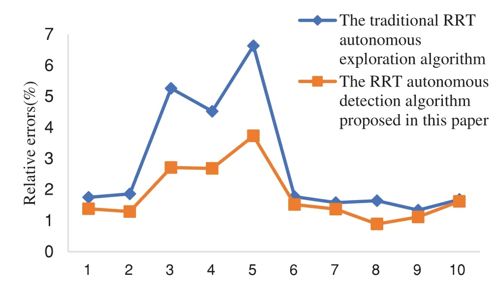
Figure 13:Comparison of the relative errors of the detection results of two different autonomous detection algorithms in experimental setting 2
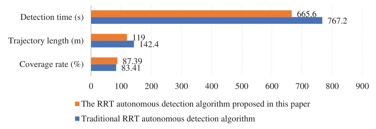
Figure 14:A comparison chart of average exploration performance indexes between two different autonomous detection algorithms in experimental environment 2
By combining the experimental results in the two three-dimensional simulation environments,it could be found that the RRT autonomous detection algorithm proposed in this paper performed localization and mapping more accurately and expressed the surrounding environment more accurately than conventional RRT autonomous detection algorithm with the increase in the surrounding obstacles,the spatial complexity,and the length of the autonomous detection trajectory.The experimental results showed that the RRT autonomous detection algorithm proposed in this paper,with an average detection coverage rate higher than that of the traditional RRT autonomous exploration algorithm,can effectively reduce the autonomous detection time and planning and detection trajectory length,and efficiently complete the autonomous detection and mapping task,thereby verifying its superiority.
4.2 Actual Scene Experiment
4.2.1 Experimental Environmental Design
Restricted by the size of the open field and the number of experimental props and considering the working time of the robot battery and the intensity of outdoor wireless communication signals,two realistic obstacle environments were established indoors using waste debris,namely,one 6.08 × 7.12 m2simple obstacle environment and one 5.12 × 6.95 m2environment with complex obstacles.Each obstacle environment was encircled by boards and cartons.There was only an obstacle encircled by cartons in the simple obstacle environment,while circular cones and rectangular cartons were placed in the environment with complex obstacles.According to [28],the following constants and variables were set in the autonomous detection experiment of the mobile robot: the physical dimensions,maximum linear velocity,maximum angular velocity,maximum linear acceleration,and maximum angular acceleration of the mobile robot were 0.25 m × 0.22 m × 0.2 m,0.35 m/s,0.63 rad/s,0.25 m/s,and 0.8 rad/s,respectively.The maximum measuring distance of the lidar was 12 m,the accuracy of the robot’s free-passage map was 0.01 m,and the expansion radius of the cost map was 0.55 m.
4.2.2 Experimental Verification of Actual Scenarios and Results Analysis
In this experiment,the accuracy and practicability of the RRT autonomous detection algorithm proposed in this paper in the realistic autonomous mapping of the mobile robot were verified under two different actual obstacle environments and compared with those of the traditional RRT autonomous detection algorithm.The global random search tree growth rate valueηgand the local random search tree growth rate valueηlwere set in different obstacle actual environments in the method of reference[10].
(1)Actual environment 1:actual simple obstacle environment
The growth rateηgof the global random search tree was 20 and that (ηl) of the local random search tree was 5.The mobile robot was initially rightly above the actual obstacle environment,as shown in Fig.15a.Exploration and mapping were performed using the two different autonomous detection algorithms under actual environment 1.The operation effects of the exploration starting in the actual environment and RViz visualization tool are shown in Figs.15a and 15b,respectively.The operation effects of the exploration process in the actual environment and RViz visualization tool are shown in Figs.15c and 15d,respectively.The operation effects of the exploration ending in the actual environment and RViz visualization tool are shown in Figs.15e and 15f,respectively.
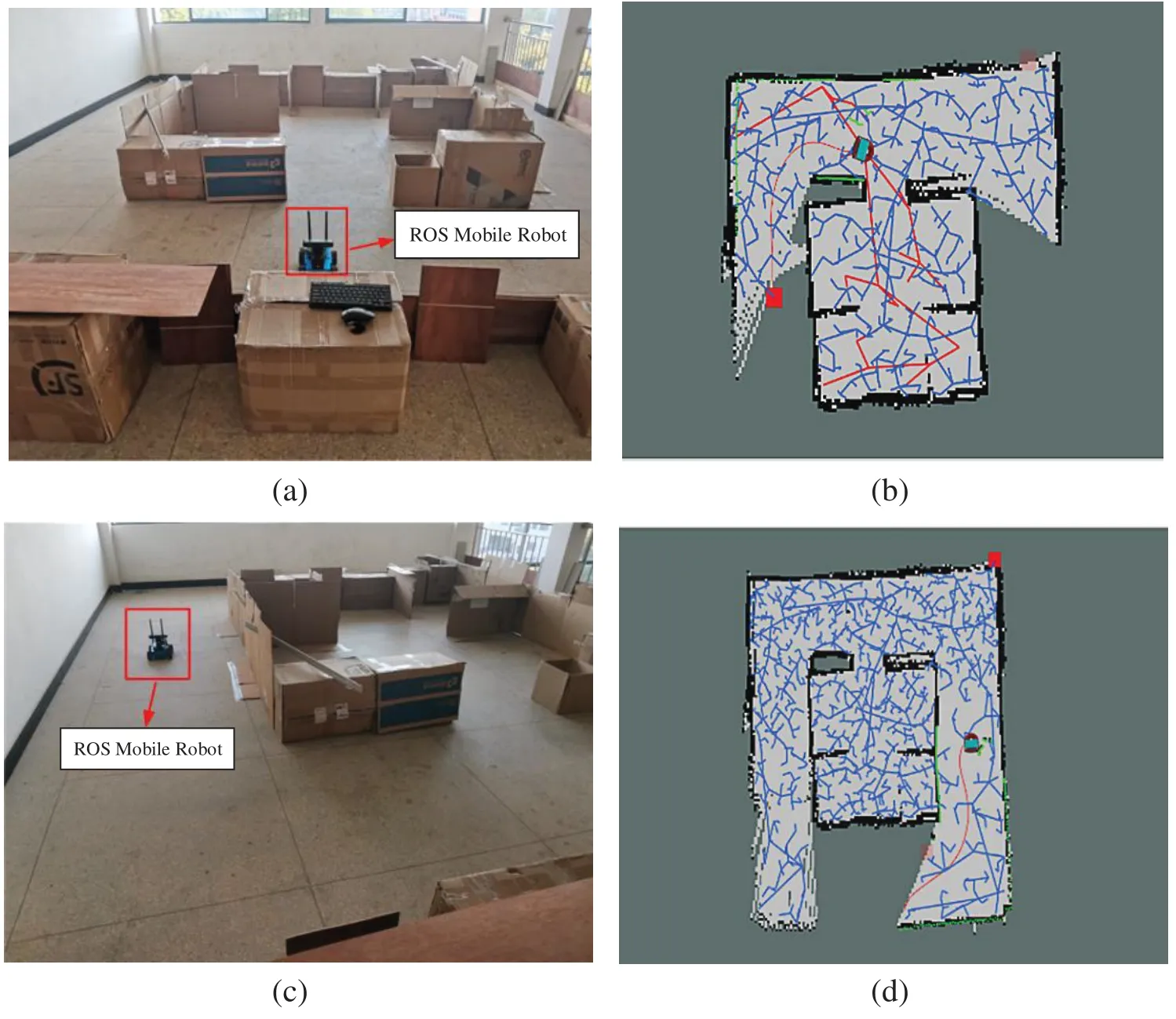
Figure 15:(Continued)
The mapping results of the traditional RRT autonomous exploration algorithm are displayed in Fig.16 and those of the RRT autonomous detection algorithm proposed in this paper are shown in Fig.17.
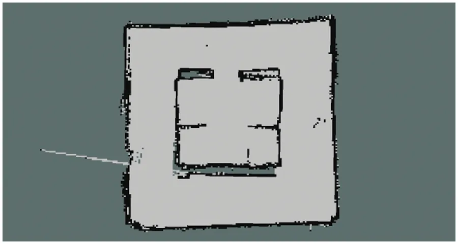
Figure 16:Mapping results of the traditional RRT autonomous exploration algorithm in actual environment 1
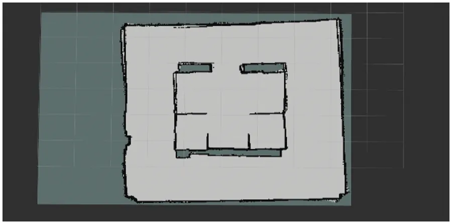
Figure 17:Mapping results of the RRT autonomous detection algorithm proposed in this paper in actual environment 1
It could be intuitively seen from Figs.16 and 17 that certain remnant drifting traces existed in the obstacle-free passage region as manifested in the detection result of the traditional RRT autonomous exploration strategy,accompanied by a fuzzy description of the obstacle periphery and the wall surface.The obstacle periphery and the wall surface were clearly described by the results of the RRT autonomous detection algorithm proposed in this paper,which accurately expressed the actual environmental situation.
As could be seen from Fig.18,in an actual environment of simple obstacles,the RRT autonomous detection algorithm proposed in this paper had a higher average coverage of 5.65%,a faster average autonomous detection time of 3.6 s,and a shorter average detection trajectory length of 3.43 meters compared to the traditional RRT autonomous detection algorithm.

Figure 18:A comparison chart of average exploration performance indexes between two different autonomous detection algorithms in actual environment 1
(2)Actual environment 2:actual environment with complex obstacles
The growth rateηgof the global random search tree was 40 and that (ηl) of the local random search tree was 5.The mobile robot was initially at the upper right of the actual obstacle environment,as shown in Fig.19a.Exploration and mapping were performed using the two different autonomous detection algorithms in the actual environment 2.The operation effects of the exploration starting in the actual environment and RViz visualization tool are shown in Figs.19a and 19b,respectively.The operation effects of the exploration process in the actual environment and RViz visualization tool are shown in Figs.19c and 19d,respectively.The operation effects of the exploration ending in the actual environment and RViz visualization tool are shown in Figs.19e and 19f,respectively.
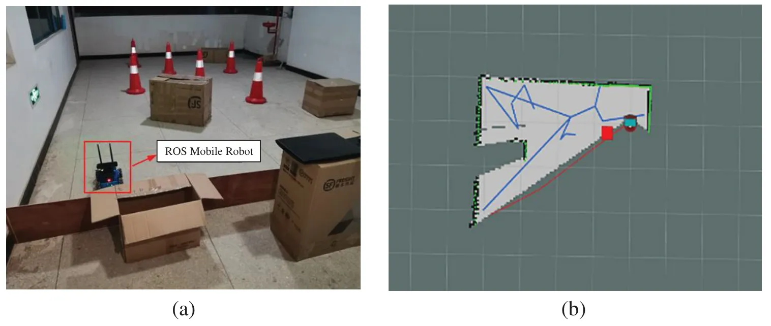
Figure 19:(Continued)
The mapping results of the traditional RRT autonomous exploration algorithm are exhibited in Fig.20 and those of the RRT autonomous detection algorithm proposed in this paper are shown in Fig.21.The average index values like autonomous detection time,exploration trajectory length,and coverage rate of autonomous detection obtained by the two different autonomous exploration algorithms running in actual environment 2 were compared,as displayed in Fig.22.
As intuitively seen from Figs.20 and 21,drifting distortion existed in the description of the obstacle periphery and the wall surface by the detection results of the traditional RRT autonomous exploration algorithm,while rectangular cartons and circular cones were fuzzily expressed.From the results obtained by the RRT autonomous detection algorithm proposed in this paper,the rectangular cartons and circular cones were expressed clearly,and the established map conformed to the actual environmental situation more.
From Fig.22,it can be seen that in the actual environment of complex obstacles,the RRT autonomous detection algorithm proposed in this paper had a higher average coverage of 17.32%,a faster average autonomous detection time of 22.63%,and a shorter average detection trajectory length of 22.61% compared with the traditional RRT autonomous detection algorithm.
Combining the experimental results in the two actual obstacle environments,it could be seen that the autonomous exploration time and planning trajectory length of both autonomous detection strategies increased with the increase in the surrounding obstacles and the spatial complexity.However,the average detection coverage rate of the RRT autonomous detection algorithm proposed in this paper became increasingly higher while that of the traditional RRT autonomous detection algorithm showed an opposite trend.That is because the mobile robot will repeatedly pass through some positions or even turn aroundin situin the process of RRT autonomous exploration,to detect the position of unexplored regions and ensure the integrity of the corners of explored regions.As the length of the detection track increased,the cumulative error of the odometer also increased,and the traditional RRT autonomous detection algorithm relied on the odometer,which led to the distortion of the autonomous map construction.The graph optimization-based Karto SLAM algorithm could effectively eliminate the cumulative error of odometers.The Karto SLAM algorithm had enough time for rear-end optimization with the extension of autonomous detection time,thus contributing to more accurate localization and mapping.At the same time,the autonomous detection time and planning and detection trajectory length were effectively reduced in cooperation with the RRT autonomous detection algorithm proposed in this paper.
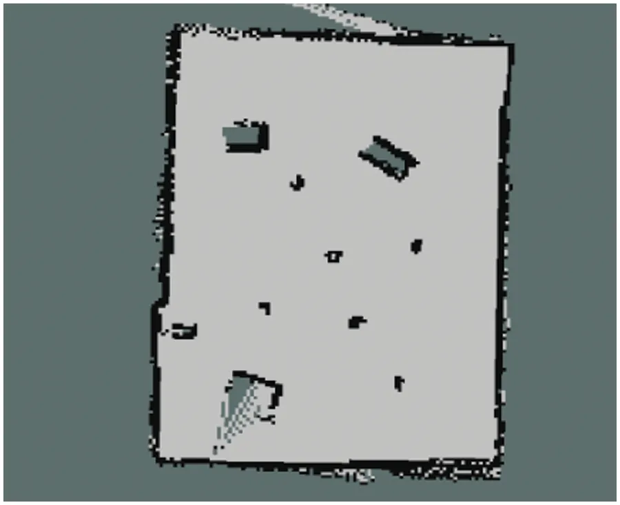
Figure 20:Mapping results of the traditional RRT autonomous exploration algorithm in actual environment 2
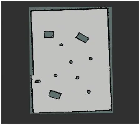
Figure 21:Mapping results of the RRT autonomous detection algorithm proposed in this paper in actual environment 2
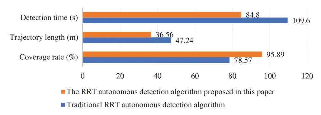
Figure 22:A comparison chart of average exploration performance indexes between two different autonomous detection algorithms in actual environment 2
5 Conclusions
Aiming at the problems of low efficiency of detecting frontier boundary points and drift distortion in the process of map building in the traditional RRT autonomous detection algorithm,this paper carried out two aspects of improvement.On the one hand,the random sampling function with a multi-pilot-point bias strategy was designed to improve the convergence performance of the global frontier boundary point detection algorithm of the traditional RRT.On the other hand,the improved RRT algorithm was integrated with the Karto SLAM algorithm,which made the traditional RRT autonomous detection algorithm improve the situation of drift distortion in the map-building process.This paper verified the traditional RRT autonomous detection algorithm and the RRT autonomous detection algorithm proposed through simulation experiments and actual scene experiments.The experimental results show that the proposed RRT autonomous detection algorithm was better than the traditional algorithm in terms of detection coverage,detection time,and detection track length,which improved the efficiency of autonomous detection and the accuracy of detection results.However,the proposed RRT autonomous detection algorithm still failed to solve the problem of repeated exploration,which was to be further studied later.In addition,although the simulation environment designed in this paper and the actual scene environment had a certain degree of complexity,they were all static environments,and further research should be carried out later on dynamic obstacles,dynamic targets,and other dynamic environments,which were more valuable.
Acknowledgement:The authors wish to express sincere appreciation to the reviewers for their valuable comments,which significantly improved this paper.
Funding Statement:This research was funded by National Natural Science Foundation of China(No.62063006);Guangxi Science and Technology Major Program (No.2022AA05002);Key Laboratory of AI and Information Processing (Hechi University),Education Department of Guangxi Zhuang Autonomous Region(No.2022GXZDSY003);Guangxi Key Laboratory of Spatial Information and Geomatics (Guilin University of Technology) (No.21-238-21-16);Innovation Project of Guangxi Graduate Education(No.YCSW2023352).
Author Contributions:The authors confirm contribution to the paper as follows: study conception and design:Lieping Zhang,Jianchu Zou;data collection:Xiaoxu Shi;analysis and interpretation of results:Lieping Zhang,Yilin Wang,Jianchu Zou;draft manuscript preparation:Jiansheng Peng,Liu Tang.All authors reviewed the results and approved the final version of the manuscript.
Availability of Data and Materials:The data used to support the findings of this study are available from the corresponding author upon request.
Conflicts of Interest:The authors declare that they have no conflicts of interest to report regarding the present study.
杂志排行
Computers Materials&Continua的其它文章
- ASLP-DL—A Novel Approach Employing Lightweight Deep Learning Framework for Optimizing Accident Severity Level Prediction
- A Normalizing Flow-Based Bidirectional Mapping Residual Network for Unsupervised Defect Detection
- Improved Data Stream Clustering Method:Incorporating KD-Tree for Typicality and Eccentricity-Based Approach
- MCWOA Scheduler:Modified Chimp-Whale Optimization Algorithm for Task Scheduling in Cloud Computing
- A Review of the Application of Artificial Intelligence in Orthopedic Diseases
- IR-YOLO:Real-Time Infrared Vehicle and Pedestrian Detection
