End-to-end computational design for an EUV solar corona multispectral imager with stray light suppression
2024-03-04JinmingGaoYueSunYinxuBianJilongPengQianYuCuifangKuangXiangzhaoWangXuLiuXiangqunCui
Jinming Gao, Yue Sun, Yinxu Bian, Jilong Peng, Qian Yu, Cuifang Kuang*,Xiangzhao Wang, Xu Liu, Xiangqun Cui*
1State Key Laboratory of Extreme Photonics and Instrumentation, College of Optical Science and Engineering,Zhejiang University, Hangzhou 310027, China
2ZJU-Hangzhou Global Scientific and Technological Innovation Center, Zhejiang University, Hangzhou 310027, China
3Nanjing Institute of Astronomical Optics & Technology, Chinese Academy of Sciences, Nanjing 210042, China
4Beijing Environmental Satellite Engineering Institute, Beijing 100094, China
Abstract: An extreme ultraviolet solar corona multispectral imager can allow direct observation of high temperature coronal plasma, which is related to solar flares, coronal mass ejections and other significant coronal activities.This manuscript proposes a novel end-to-end computational design method for an extreme ultraviolet (EUV) solar corona multispectral imager operating at wavelengths near 100 nm, including a stray light suppression design and computational image recovery.To suppress the strong stray light from the solar disk, an outer opto-mechanical structure is designed to protect the imaging component of the system.Considering the low reflectivity (less than 70%)and strong-scattering (roughness) of existing extreme ultraviolet optical elements, the imaging component comprises only a primary mirror and a curved grating.A Lyot aperture is used to further suppress any residual stray light.Finally, a deep learning computational imaging method is used to correct the individual multi-wavelength images from the original recorded multi-slit data.In results and data, this can achieve a far-field angular resolution below 7", and spectral resolution below 0.05 nm.The field of view is ±3 R⊙ along the multi-slit moving direction, where R⊙represents the radius of the solar disk.The ratio of the corona's stray light intensity to the solar center's irradiation intensity is less than 10-6 at the circle of 1.3 R⊙.
Keywords: EUV solar corona imager; Curved grating; Stray light suppression; Computational multispectral imaging
1.INTRODUCTION
Solar coronal observation is very important for the protection of both spacecraft and planet Earth.The EUV band is significantly different to visible light and other bands of electromagnetic radiation, with a shorter wavelength and higher photon energy[1-3].Because this band is strongly absorbed by Earth’s atmosphere, EUV telescope imagers work best in space.An EUV solar corona imager can enable direct observations of high temperature coronal plasma, and the most attractive for this application are multispectral imagers, consisting of a wide field imager and a spectrometer.Most materials absorb EUV radiation,preventing the use of prisms and transmissive optical elements.Additionally, due to the low EUV reflectivity of materials, it is unrealistic to add too many reflective elements[4,5]into EUV multispectral imagers.For example,a basic reflective Fourier transform imaging spectrometer,in which light is reflected several times, is inappropriate for EUV light[6-8].Some EUV thin-film filters have been used in the EUV imager on the Solar Dynamics Observatory satellite and the Atmospheric Imaging Assembly satellite, but these only have a spectral resolution of approximately 0.5 nm[9-12].
With advancements in multilayer film and grating fabrication techniques, curved gratings have been introduced into EUV spectrometers.These curved gratings have unique diffraction capabilities, enabling spectral imaging and dispersion with only a single grating, reducing the system's reflective and diffractive surfaces significantly[13-15].Consequently, an EUV solar corona multispectral imager would combine a telescope system with a curved grating[16-18].The telescope images the incident light into a slit, which serves as both the field stop for the telescope and the slit for the spectrometer[19].The curved grating here works simultaneously as both imager and grating, removing the requirement to collimate mirrors, thus greatly improving the system sensitivity.The system can achieve a wide field-of-view (FOV) through scanning movement of the slits[20-22].The CORONA project(America’s first satellite program) employed a planar grating combined with a focusing mirror[23-25], able to perform multispectral imaging with high spectral resolution and wide FOV[26].
For an EUV solar corona multispectral imager with high sensitivity and efficiency, we propose an end-to-end computational design method with separate optical elements and a deep learning computational image recovery algorithm.For suppressing stray light from the solar disk,the external occulter (EO) is innovatively designed, with an annular light aperture and an inclined spherical mirror with a central opening.For the imaging component, the simplest configuration is adopted, with only a primary mirror and a curved grating, which can achieve both high spatial and spectral resolution in a wide FOV.A unique multi-slit arrangement greatly improves the scanning efficiency.In addition, enhancement by deep learning (DL)methods can correct distortion caused by the curved grating.The entire system comprises only two optical reflective surfaces, ensuring high transmission efficiency.
2.RESULTS
2.1.The EUV Solar Corona Multispectral Imager System
The main specifications of the EUV solar corona multispectral imager system are listed in Table 1.The EUV spectral ranges is 94 nm to 109 nm, namely 94 nm, 97.5 nm,97.7 nm, 102.5 nm, 103.2 nm, 103.7 nm and 109 nm.The half-angle of FOV along the multi-slit moving direction is 3R⊙and the half-FOV along the slit is 2R⊙.The spectral resolution is better than 0.05 nm, and the far-field angle resolution is better than 7".The design uses 5 slits for parallel-scanning spectral imaging.The design of the EUV solar corona multispectral imager is shown in Fig.1, including an EO structure, entrance pupil stop, offaxis primary mirror, multi-slit plane, spectral dispersion component, and Complementary Metal-Oxide-Semiconductor (CMOS) image sensor.As stray light beams from the solar disk are very strong, they should be prevented from entering the aperture, so an outer stray light suppression component is required before the imaging system.The primary mirror is then placed after the entrance pupil stop.The primary mirror is an off-axis parabolic mirror and is used to capture the first image of the solar corona, with the 5-slit multi-slit mask placed at the imaging plane of the primary mirror.A curved grating is used for multispectral imaging, conjugately imaging the first image plane to the CMOS image sensor.A Lyot stop is placed at the exit pupil to suppress stray light.The CMOS image sensor is placed on a tilted plane.Fig.2 shows the quantitative imaging performance of the system, including root mean square (RMS) data, spot radii, and modulation transfer functions (MTFs).In Fig.2A, B and C, the RMS spot radii are all below 10 μm, where the pixel size of the CMOS image sensor is 25 μm.Additionally, the MTF is better than 0.2 at 40 lp/mm across all FOVs, at wavelengths of 94 nm, 102.5 nm, and 109 nm.
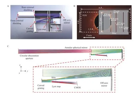
Fig.1.Schematic of the EUV solar corona multispectral imager.(A) Opto-mechanical structure, from the outer stray light suppression component to the CMOS image sensor.(B) Slit mask for multi-slit scanning used in EUV multispectral imaging.(C) Optical light path, including outer stray light suppression and imaging components.

Fig.2.Image performance of the EUV solar corona multispectral imager system.(A) RMS spot radii change with wavelength under different FOVs.(B)-(C) RMS spot radii versus FOV at different wavelengths.(D)-(F) MTF of the optical system at wavelengths of 94 nm, 102.5 nm, and 109 nm.

Table 1.EUV solar corona multispectral imager system specifications
2.2.Stray Light Suppression
To prevent stray light radiation from the solar disk,an outer stray light suppression shielding system is employed.The opto-mechanical structure is shown in Fig.3A, with two separated components.The front body includes a circular obscuration aperture (COA), while the rear body employs an annular spherical mirror aperture(ASMA).Fig.3B shows the irradiance distribution of the annular incident window, and Fig.3C shows the irradiance distribution on the primary mirror of the coronagraph, within the FOV of 0-2R⊙.Results indicate that rays within the 0-1.3R⊙FOV are imaged at the annular aperture and kept out of the imaging apparatus, where the ratio of the corona's stray light intensity to the solar center's irradiation intensity is less than 10-6at the circle of 1.3R⊙.

Fig.3.The EO.(A) Mechanical structure of optics.(B) Irradiance distribution at the annular aperture.(C) Irradiance distribution at the image plane of the primary mirror and the multi-slit plane.
There are two main sources through which stray light can be introduced into the imaging system, which can reduce the image contrast of the CMOS image sensor.One source is light diffracting and scattering at the edge of each element.Another, as the EUV wavelength is short, is from light scattering off any roughness or defects in the mirror and grating.To minimize the effects of this,a Lyot stop is placed at the exit pupil of the imaging component, as shown in Fig.4A.Calculations show that the diffracted light forms an annular illumination pattern witha diameter of 8.9 mm at the location of the Lyot stop.Consequently, the optical diameter of the Lyot stop is set to 8.7 mm to completely block the diffracted light.The Lyot stop is positioned 178.2 mm before the image plane with a tilt angle of -6.2°.The system vignetting caused by the Lyot stop is shown in Fig.4B.The maximum unvignetted light fraction of the system is over 95%, which will not influence the image quality.Finally, stray light is suppressed less than 10-6at the circle of 1.3 R⊙.
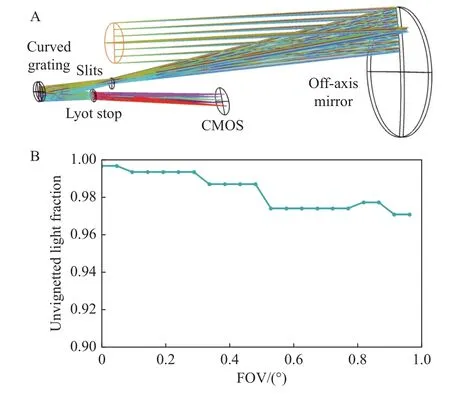
Fig.4.Lyot stop to suppress stray light rays in the imaging system.(A) Position of the Lyot stop.(B) Vignetting calculation of the system caused by the Lyot stop.Please note that the y-axis here shows only 0.9-1.
2.3.Primary Mirror
A primary mirror is used for the first imaging, which is also the multi-slit plane.Here, an off-axis parabolic mirror works as the primary mirror, similarly to a telescope objective, the design parameters of which are given in Table 2.The radius of the parabolic mirror is -810 mm,the conic coefficient is -1, the decentration is 50 mm,and the clear aperture is 55.4 mm.The surface sagittal height profile and the cross-sectional sagittal height profile of the primary mirror are shown in Fig.5.
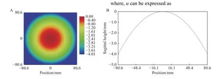
Fig.5.Sagittal height of the primary mirror.(A) Surface sagittal height diagram.(B) Cross-sectional sagittal height diagram.

Fig.6.Sagittal height diagram of curved grating.(A) Surface sagittal height diagram.(B) Cross-sectional sagittal height diagram.

Table 2.Primary mirror parameters
2.4.Curved Grating
The parameters of the curved grating are divided into two parts: surface shape parameters and engraved line parameters.The surface shape is composed of an ellipsoid base surface superposed with XY extended polynomials.The surface shape expression is expressed as
In Eq.(1) and Eq.(2),x,yandzare the intercept coordinates of the intersection point between the light ray and the surface, whilea,b, andcare the coefficients defining the major and minor axes of the elliptical shape.The grating line density is given by
The specific surface parameters of the grating are shown in Table 3, Table 4, and Table 5.The surface sagittal height diagram and the cross-sectional sagittal height diagram of the grating are shown in Figure 6.

Table 3.Grating surface parameters

Table 4.Surface sagittal height polynomial parameters

Table 5.Grating line density parameters
Fig.7 displays the grating line density corresponding to the center position of the spot, indicating that the groove density varies with the relative position in the Y direction.The relative landing point position of the edge ray of the target FOV on the diffraction grating surface is-13.31 mm.The corresponding grating line density at this point is 2034 lines/mm.The relative landing point position of the lower edge ray of the target FOV on the diffraction grating surface is 13.31 mm, the grating line density corresponding to this point is 1970 lines/mm.Using Eq.(3) to integrate the spot range, the total number of slots obtained is 36 432, which meets the system's requirements for spectral resolution.

Fig.7.Grating line density distribution map.The diameter of the curved grating is 40 mm.As examples, the point position at-13.31 mm on the diffraction grating surface has a grating line density of 2034 lines/mm, while the point position at 13.31 mm has a grating line density of 1970 lines/mm.
2.5.Computational Multispectral Image Correction
Each original spectral image is stitched from slit-bar data, which is directly recorded by the CMOS image sensor.These stitched images contain distortion commonly found in slit-scanning spectral imagers.A DL method with a convolutional neural network (CNN) is used to correct imaging distortion for the stitched spectral images, as shown in Fig.8.We use a total of 5 000 sets of data to train and test the performance of our computational multispectral image recovery, constructed within the PyTorch DL framework.The input and target values of the CNN are distorted corona images and ideal coronal images respectively.4 500 sets are used for training the CNN network and 500 sets are used for testing.A total of 20 epochs are performed, and the entire calculation process is performed on a desktop computer running the Microsoft Windows 10 operating system, with Core i7-7700K CPU @ 4.2GHz (Intel) with 64GB RAM and GeForce RTX2080Ti GPU (NVIDIA) hardware.The training time is approximately 2 hours, and the correction time of a single image is less than 200 ms.Test results are shown in Fig.8.In 500 sets of test data, the average structural similarity value of the corrected images and raw image reaches 0.898, which is higher than the 0.769 of the distorted images.
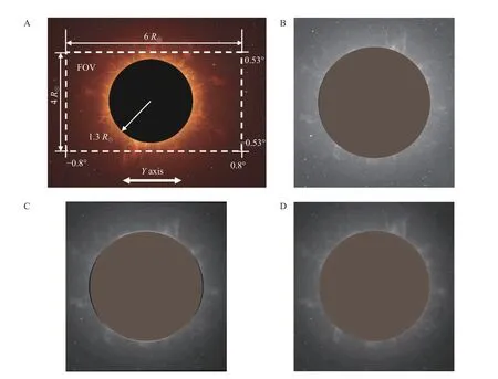
Fig.8.Deep learning distortion correction for multispectral images correction.The reddish-brown area in the figure shows perfectly circular masks.(A) Imaging FOV diagram.(B) Simulated solar corona raw image.(C) Stitched image after slit scanning,from slit-bar data at 94 nm, with distortion.(D) Output of the deep learning CNN, without distortion.
3.DISCUSSION
There are two important considerations for an EUV solar corona multispectral imager, which can easily be overlooked.The first is to suppress stray light.Light from the solar disk is very strong, and this must be excluded from the imaging component.Additionally, to avoid internal scattering within the apparatus, the edges of all apertures should be crafted with minimal imperfections.All mechanical structures should be coated in light-absorbing material to minimize reflected light.Meanwhile, the mechanical structure should be strong and any vibrations should be sufficiently dampened to survive a rocket launch.Therefore, the mechanical structure should be designed with multiple chambers, with good inner space distribution, to give the instrument increased stability.This can also limit the propagation of scattered light within each narrow individual chamber, preventing the proliferation of stray light.
The second consideration is to design and arrange suitable slits, as detailed in Section 5.The slit width should match the optical resolution and the pixel size of the CMOS image sensor.If the slits are too narrow, diffraction and exposure time can become problematic, but slits which are too wide will reduce spatial resolution to unacceptable levels.Additionally, the energy distribution of the EUV spectrum peaks at a specific wavelength.The arrangement of slits must be considered according the wavelength distribution produced by the curved grating.
4.CONCLUSION
In this paper, we propose an end-to-end computational design method for an EUV solar corona multispectral imager with high sensitivity and efficiency.It uses a design with separate optical elements and a DL computational image correction algorithm.The design uses an external EO with an annular light aperture and an inclined spherical mirror with a central opening, to suppress stray light from the solar disk, with a unique multi-slit arrangement to greatly improve scanning efficiency.The entire system comprises only two optical reflective surfaces, ensuring high transmission efficiency.Following image acquisition,distortion from the curved grating can be corrected using a CNN.From the design results, the EO enhances stray light suppression, and the spectrometer exhibits outstanding spatial and spectral imaging performance.The farfield angular resolution of this design is better than 7",and the spectral resolution is better than 0.05 nm.The FOV is ±3R⊙along the multi-slit moving direction.The ratio of the corona's stray light intensity to the solar center's irradiation intensity is less than 10-6at the circle of 1.3R⊙.We believe that this novel method can lead to the design and development of further new EUV spectral imaging systems.
5.METHODS
5.1.End-to-end Computational Design
An end-to-end computational design for the EUV solar corona multispectral imager is presented in Fig.9.The physical imaging model is generalized, from the object ‘ solar corona’ to the final recovered images.In Fig.9B, a stepwise approach is adopted based on imaging requirements, culminating in the final imaging criteria.To block the solar surface radiation from the coronagraph system as early as possible, the design of the EO and the vignette analysis are carried out first.Then, to obtain a clear image of the solar corona at the slit position, the telescope primary mirror is designed computationally.To reduce the full-field scanning imaging time and eliminate the overlap of imaging spectral lines in different FOV, it is necessary to determine the number of slits and slit arrangement.Finally, DL computational image recovery is used to correct aberrations and improve image quality.

Fig.9.End-to-end computational design for the EUV solar corona multispectral imager.(A) The end-to-end roadmap from the object ‘solar corona’ to the final recovered images.(B) Each design point, including stray light suppression, telescope objective, multislit mask, curved grating and the deep learning recovery algorithm, along the end-to-end roadmap.
5.2.Design of Stray Light Suppression Components
A schematic diagram of the EO stray light suppression structure is shown in Fig.10.The structure consists of a COA and an ASMA with an inclination angle ψ.The center of the COA is an occluder, and the center of the ASMA is an aperture with a radius ofr0.A spherical mirror with a specific tilt angle, ψ, can image the sun at the annular optical entrance, thereby reflecting it out of the solar corona imager.The inner radius of the COA isr1, the outer radius isr2, and the positionsE0andM0are separated by distance,L.If the image of the sun is located onE0, the distancedbetween the image center and the COA center needs to satisfy the formula where,
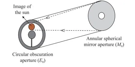
Fig.10.EO stray light suppression structure and design.It consists of a COA and an ASMA with an inclination angle.The center of the COA is an occluder, with an aperture at the center of the ASMA.The spherical mirror images the sun at the annular optical entrance, thereby reflecting it out of the solar corona imager.
his the half-height of the image of the sun, so that Ψ satisfies the formula
Here, θ0is the half-FOV angle of the solar surface image, and θ1is the maximum half-FOV angle of the solar coronal image.All light rays from 0- θ0will be intercepted by the ASMA, will be imaged on the surface of the annular entrance where the COA is located, and will be reflected out of the solar corona imager.All the solar coronal light from θ0- θ1enters the system, while the light greater than θ1will be partially intercepted by the ASMA.If the pointing accuracy of the satellite isφ, thenr1andr2satisfy the equation
5.3.Primary Mirror Design
To meet the desired spatial and spectral resolution requirements, clear imaging at the primary image plane of the system is needed, i.e., at the slit position.The main mirror adopts an off-axis parabolic design[27].When determining the parameters of the off-axis paraboloid, the following factors should be comprehensively considered: (1)Since a multi-slit plane is placed at the primary image plane of the primary mirror and an image of the corona region is obtained through scanning the multi-slit device,the imaging focusing performance (spot focusing diameter) of the primary mirror needs to match the width of the slit.(2) The focal length of the spectral imaging system only depends on the focal length of the primary mirror and the magnification of the curved grating.Therefore,the focal length design of the off-axis parabolic primary mirror needs to match the spatial resolution[28].(3) To avoid mechanical interference between the optical path and optical elements, there should be sufficient space for mechanical structure assembly and adjustment.The offaxis parabolic mirror needs to be sufficiently off-axis.At the same time, the off-axis paraboloid serves as the front telescope system of the spectral imager, and its design needs to meet the imaging focusing performance of the target FOV at the final image plane[29-31].
5.4.Slit Distribution Design
The multi-slit plane is located at the primary image plane and consists of straight slits with unequal spacing,as shown in Fig.11.From the focal length of the telescope imaging system, the field diaphragm size at the first image plane can be calculated as
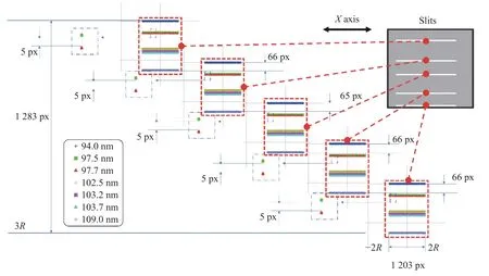
Fig.11.Schematic diagram of the multi-slit mask, where ‘px’ denotes size in pixels.The spectral dispersion distributions corresponding to the five slits are independent and are located together on the CMOS image sensor.The spectral bandwidths will partially overlap, but the spectral line positions do not overlap.
where,YFSis the width in theYdirection andXFSis the length in theXdirection.In Fig.11,Nw+(N-1)ds,i=YFS, wherewis the slit width,ds,iis the slit spacing, andNis the number of slits.The image of the slit through the grating has a widthw1on the CMOS image sensor.The spectra produced byw1will partially overlap, limiting the resolvable spectral bandwidth.The spectral resolution corresponding to the geometric width of the slit image should satisfy
Multiple slits enable different spectral line segments at different FOVs to be imaged on the CMOS image sensor simultaneously.To reduce the time cost, multiple slits should be involved in imaging while ensuring spectral resolution.The slit spacingds,ican be calculated with the formula
where,ds,iis the spacing between i slits,dm,iis the minimum spacing between slitsiandi+1 on the image plane,andβis the magnification of the curved grating.
5.5.Curved Grating Design
To correct chromatic aberration and obtain high spectral resolution imaging, the spectral dispersion system uses a variable line spacing curved grating.The aberration correction principle diagram is shown in Fig.12.The pointA0(xa,ya,0) is the center of the slit, andAA0is any off-axis light source parallel to the grating line.The pointP(x,y,z)is any point on the grating surface.After the incident light raysAPandAOpass through the curved grating, they are imaged at pointB(xb,yb,zb).B0(xb,yb,0) is the projection of pointBon the planeXOY.The angleibetween the lightA0Oand theX- axis is the incident angle, and |OA0|=rAis the incident arm length of the grating.The angleθbetween the lightB0Oand theX-axis is the diffraction angle, and |OB0|=rBis the exit arm length of the grating.The surface sag of the grating can be expressed using Eq.(1).The density of the grating changes along theY-axis.The total number of gratings can be expressed as
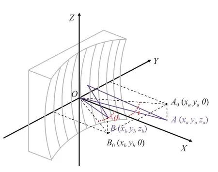
Fig.12.Diagram of the curved surface variable line pitch grating.
where,N(y) is the total number of score lines accumulated from the originOto any pointPin theYdirection,d0is the score line spacing at the originO, and ζiis the spatial variation parameter of the score line density.Bringing the coordinates of each point into the optical path function ofAPBand expanding it into the Taylor series ofyandz, we obtain
In Eq.(11),jandkcannot simultaneously be zero,and each term corresponds to a grating aberration of the curved grating.By optimizing the spatial variation parameters of the curved grating, the spectral focus curve and the spatial focus curve can be made to intersect at the astigmatic point, thereby achieving non-atigmatism imaging.Through the optimization of superposition polynomials,high-order aberrations can be corrected and the optimal solution of the system can be obtained.
5.6.Computational Imaging Method
The stitched image will inevitably have distortion,caused by the slit-bar data recorded with the CMOS image sensor, like a smile curve.Although small, this distortion is still non-negligible.This is caused by the inherent characteristics of the curved grating and off-axis imaging.Therefore, it is necessary to perform computational post-processing on the distorted stitched solar coronal image to obtain a corrected solar coronal image.The essence of the image distortion correction problem is to spatially transform the distorted image, and the transformation relationship is fixed in this system.A DL CNN can be used to fit this transformation[32-34], which is shown in Fig.13.The entire process can be viewed as feature extraction of the input image and pixel-by-pixel regression of the output results[35,36].Therefore, the CNN first convolves and down-samples the input data, performs feature transformation in 9 residual blocks, and finally up-samples through transposed convolution to reconstruct a distortion-free image.When training the model, we use the mean square error loss as the loss function, which is expressed as
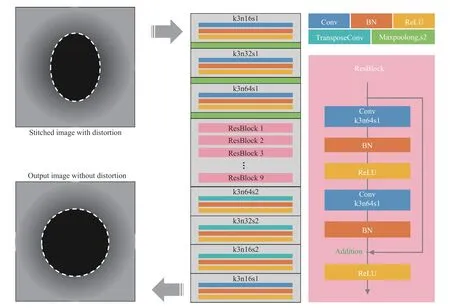
Fig.13.Schematic diagram of our deep learning CNN.The input is a distorted stitched solar coronal image and the output is a corrected solar coronal image.The network layers used in the CNN structure are shown to the right.
where,Yiis the ideal coronal image,is the reconstructed coronal image, andnis the number of elements of the output tensor.
6.AVAILABILITY OF DATA AND MATERIALS
All data needed to evaluate the conclusions in this study are presented in this manuscript.Additional data related to this paper may be requested from the authors.
7.ABBREVIATIONS
ASMA: Annular Spherical Mirror Aperture
CME: Coronal Mass Ejection
CMOS: Complementary Metal-Oxide-Semiconductor
CNN: Convolutional Neural Network
COA: Circular Obscuration Aperture
DL: Deep Learning
EO: External Occulter
EUV: Extreme Ultraviolet
FOV: Field Of View
MTF: Modulation Transfer Function
RMS: Root Mean Square
SDO: Solar Dynamics Observatory
ACKNOWLEDEGMENTS
This study is partially supported by the National Natural Science Foundation of China (NSFC) (62005120;62125504).
AUTHOR CONTRIBUTIONS
Cuifang Kuang and Xiangqun Cui conceived the idea and initiated the project.Jinming Gao, Yinxu Bian and Yue Sun mainly wrote the manuscript and produced the figures.Jinming Gao and Yinxu Bian conducted the optical design and data experiments.Jilong Peng and Qian Yu provided algorithm support.Xiangzhao Wang and Xu Liu edited the manuscript.Xu Liu and Xiangqun Cui supervised the project.All authors read and approved the final manuscript.
DECLARATION OF INTERESTS
Xiangqun Cui is the editor-in-chief for Astronomical Techniques and Instruments and was not involved in the editorial review or the decision to publish this article.The authors declare no competing interests.
杂志排行
天文研究与技术的其它文章
- Review of artificial intelligence applications in astronomical data processing
- The Jiao Tong University Spectroscopic Telescope Project
- Characteristics and close-range exploration methods of near-Earth asteroid 2016HO3
- Design and analysis of an advanced thermal management system for the solar close observations and proximity experiments spacecraft
- Application and prospect of the fluid cooling system of solar arrays for probing the Sun
- A predictive model for regional zenith tropospheric delay correction
