High-sensitivity phase imaging eddy current magneto-optical system for carbon fiber reinforced polymers detection
2024-01-17JingShnAiQunZhouYiPingLingChunRuiFengBingLongLiBingBiYongGngWngChoRen
Jing-Shn Ai,Qun Zhou,Yi-Ping Ling,Chun-Rui Feng,Bing Long,Li-Bing Bi,* ,Yong-Gng Wng,Cho Ren
a School of Automation Engineering,University of Electronic Science and Technology of China,Chengdu,611731,China
b Department of Mechanical Engineering,Catholic University of Leuven,Leuven,3001,Belgium
c Chengdu Aircraft Industry Company Ltd.,Chengdu,610091,China
Keywords:Carbon fiber reinforced polymers Defect detection Eddy current magneto-optical Nondestructive testing Phase imaging
ABSTRACT This paper proposed a high-sensitivity phase imaging eddy current magneto-optical (PI-ECMO) system for carbon fiber reinforced polymer (CFRP)defect detection.In contrast to other eddy current-based detection systems,the proposed system employs a fixed position excitation coil while enabling the detection point to move within the detection region.This configuration effectively mitigates the interference caused by the lift-off effect,which is commonly observed in systems with moving excitation coils.Correspondingly,the relationship between the defect characteristics (orientation and position)and the surface vertical magnetic field distribution (amplitude and phase) is studied in detail by theoretical analysis and numerical simulations.Experiments conducted on woven CFRP plates demonstrate that the designed PI-ECMO system is capable of effectively detecting both surface and internal cracks,as well as impact defects.The excitation current is significantly reduced compared with traditional eddy current magneto-optical (ECMO) systems.
1 Introduction
Carbon fiber reinforced polymer (CFRP) materials are highly utilized in industries,such as aerospace and automotive [1].To ensure the quality and safety of products,various nondestructive testing (NDT) methods have been extensively employed to detect defects in CFRP [2–5].Among them,the eddy current (EC) method uses a high-frequency excitation coil to generate EC in CFRP and identify defects through the abnormal magnetic field distributions.EC has the advantages of noncontact,one-sided detection,and no radiation [6].Thus it has received much attention in research.However,due to the low electrical conductivity of CFRP,the EC-based detection requires high-sensitivity from the detection sensors.Currently,there are two main approaches to enhance sensitivity.The first approach involves high-sensitivity sensors,such as coils and superconducting quantum interference devices (SQUIDs) [7,8].The German Fraunhofer Institute for Nondestructive Testing (IZFP) has achieved significant advancements in CFRP defect detection through a high-frequency EC excitation coil [9].Rousi used SQUID which offers ultra-high responsiveness to detect subtle magnetic field changes induced by defects,even at a certain distance from the excitation coil [10].The second approach is to use separate excitation and detection sensor probes.For example,Cheng et al.utilized transmitting and receiving coils scanning imaging with excitation frequencies of 150 kHz and 250 kHz to detect cracks and impact defects in CFRP [11].However,in the aforementioned EC-based methods,the excitation coil and detection sensor are employed for synchronous scanning.Although this approach resolves the coupling issue between the excitation and detection units,it inevitably introduces lift-off interference during the scanning process at each detection point,thereby compromising the detection accuracy [12].In fact,maintaining a fixed position relationship between the excitation source and the specimen effectively mitigates these influences.However,in the EC testing for CFRP,there are limited research on detecting defects by visualizing the magnetic field spatial distribution around the fixed position excitation coil.
Eddy current magneto-optical (ECMO) imaging detects defects through the magnetic field spatial distribution [13] and was initially proposed by Fitzpatrick et al.for detecting defects in aircraft skin [14].This method employs magneto-optical (MO) sensing principles,effectively avoiding electromagnetic coupling issues between the excitation and detection units based on the physical mechanism.Numerous investigations have been conducted in the field of ECMO imaging defect detection [15–18].However,traditional ECMO imaging nondestructive testing methods are not applicable to defect detection in CFRP.The main reason is that traditional ECMO methods often use cameras for imaging,which is limited by the number of camera bits and noise,and can only achieve magnetic field resolution at a millitesla (mT) or sub-millitesla level [19].For EC CFRP defect detection,such magnetic field sensitivity is insufficient.
To address the problem associated with moving EC excitation and facilitate the application of ECMO in defect detection on CFRP,we propose a high-sensitivity phase imaging eddy current magneto-optical(PI-ECMO) system that utilizes fixed position excitation and moving phase detection.Inspired by high-sensitivity MO magnetic field detection [20,21],camera imaging is replaced with an auto-balanced photodetector and lock-in amplifier enhancing the sensitivity of magnetic field.The lock-in amplifier can also directly measure the phase,and the optical path is optimized accordingly.
In this study,both the amplitude and phase were compared through numerical simulations,demonstrating that phase detection is more sensitive.The simulations also investigated the impact of defects at different positions and orientations on the phase detection results.Experimental validation was conducted on plain woven carbon fiber plates,confirming the capability of PI-ECMO to detect cracks and impact damage.The excitation current is significantly reduced compared with traditional ECMO systems (Ampere level or higher) [22].
2 Phase imaging EC magneto-optical imaging system
In the proposed PI-ECMO system,an excitation coil is used to inject an excitationHeinto the sample plate,and then ECs are induced.If there is a defect in the sample plate,the EC distribution will change.Consequently,the EC vertical secondaryHschanges,as depicted in Fig.1.Capturing the magnetic field phase using an MO sensor,the defect detection is achieved.The PI-ECMO detailed description is provided in the following.
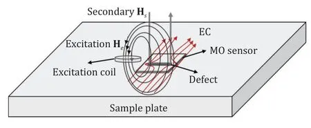
Fig.1.PI-ECMO diagram.
2.1 EC excitation model
For isotropic semi-infinite uniform conductor materials,the transient EC equation (1) expressed in magnetic field strengthHcan be derived from Maxwell’s equation,whereμis permeability,σis conductivity,andtis time.
For the time-harmonic electromagnetic field,(1) can be expressed as (2),in whichzis assumed to be the vertical direction,xandyare two horizontal components,andωis angular frequencies.
A one-dimensionalz-direction magnetic field changing alongxis used to simplify the equation calculation to get an analytic solution.Assuming that the vertical excitation magnetic field isHz(x,t)=h(x)e-iωt,the special solution can be obtained by bringing in (2),and the expression of the general solution can be obtained by bringing in the special solutionh(x)=and boundary conditions,which is shown as
Equation (3) shows that when the exciting magnetic field passes through the conductor,the generated EC makes the amplitude of the magnetic field decay and the phase of the magnetic field shift.The higher the frequency and the conductivity are,the more obvious the amplitude decay and the phase shift make.By selecting the appropriate detection position and excitation frequency,the anomaly caused by the conductivity change at the defect position can be identified through the magnetic field distribution.
2.2 Principle of magneto-optical imaging based on the Faraday effect
The PI-ECMO system uses a Faraday MO film to detect the magnetic field distribution.When a beam of linearly polarized light passes through an MO film,which is put in a magnetic field,the polarization plane will rotate for a certain angle.The simplest expression is (4),whereVis the Verdet constant,Bis the magnetic induction intensity in the direction of light propagation,andLis the light path length in the MO film.
The basic principle of MO detection is shown in Fig.2,which mainly includes a light source,polarizer,MO sensor,analyzer,and photodetector.The polarization angle between the polarizer and analyzer isα.The rotation angle of light isθ.The detected light intensity can be expressed as
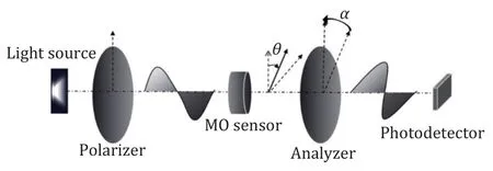
Fig.2.Principles of the magnetic field imaging by the Faraday effect.
whereI0is the light intensity incident on the analyzer andIis the light intensity passing through the analyzer.Since the changing rate of cos2(θ+α) with respect toθis the fastest when the angle ofθ+αis ±45°,in practice,for smallθ,the 45° angle ofαis usually taken to improve the sensitivity.At this time,(5) can be expressed as
Whenθis very small,the relationship between the light intensity and magnetic field can be obtained by approximating (6) according to Taylor expansion.WhenI0is constant,the measured light intensity and magnetic induction intensity have a linear relationship as
2.3 Phase imaging eddy current magneto-optical defect detection system and performance analysis
The PI-ECMO testing system depicted in Fig.3 exhibits several notable differences from other ECMO systems.One key distinction is the integration of an auto-balanced photodetector (part 10) and lock-in amplifier (part 11),which significantly enhance the magnetic field sensitivity.The optical path structure has also been optimized accordingly.
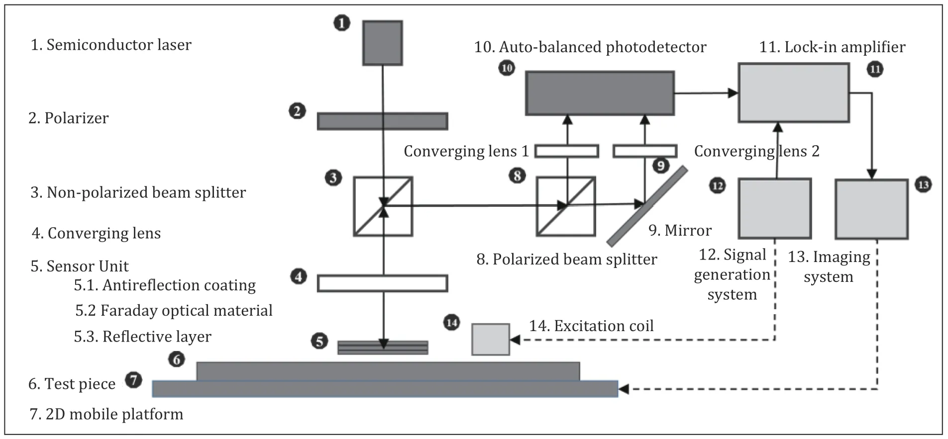
Fig.3.Experimental system diagram.
A 635 nm semiconductor laser (part 1) with adjustable power (up to 300 mW) generates a quasi-parallel beam and illuminates the polarizer (part 2).The Faraday angle of the used MO film increases as the wavelength decreases,and light absorption also increases accordingly.So,635 nm wavelength is selected to balance the light intensity and the Faraday angle.As shown in the analysis in subsection 2.2,the setting of the polarizer and analyzer at a 45° angle results in the most significant variation in light intensity with the magnetic field.The polarizer is set oriented at a 45° angle to the two splitting polarization directions of the polarized beam splitter (PBS) (part 8).A non-polarized beam splitter (NPBS) (part 3) is employed to split and change the transmission direction of the light.The polarized beam traverses NPBS,undergoes focusing via a convergence lens (part 4),and reaches the sensor unit.
The excitation coil (part 14) receives a sine excitation signal ranging from 3 mHz to 1 MHz from the signal generation system (part 12).Under the influence of the excitation magnetic field,the test piece (part 6)generates ECs that vary with the test piece conductivity distribution.Consequently,different secondary magnetic fields are generated and detected by the sensor unit (part 5).
The sensor unit comprises an upper layer antireflection coating to enhance probe light transmissivity and reduce interference from reflections.The MO thin film is positioned in the middle layer,while the bottom layer consists of germanium,which reflects the probe light back.As the probe light passes through the sensor,its polarization direction is altered due to the vertical magnetic field.The reflected probe light is redirected horizontally upon reaching NPBS and subsequently incident on PBS.After passing through PBS,the light is decomposed into two polarized beams directed toward the auto-balanced photodetector’s two sensors through converging lenses.The photodetector outputs a differential amplified electrical signal derived from the intensity of the two light beams.This signal is then transmitted to the lock-in amplifier.The time constant of the lock-in amplifier we used can be adjusted within 10 μs to 20 s.In practical detection,to obtain a more stable signal,we typically set it to 10 ms,which results in a signal stabilization time of approximately 100 ms.The data obtained from the lock-in amplifier is utilized to generate precise PI-ECMO images,which accurately represent the acquired information.Currently,the system achieves spatial movement of detection points through a two-dimensional mechanical scanning platform (part 7).
The (TmBi)3(FeGa)5O12film is used as the sensor with the sensitivity of approximately 2°/mT for 635 nm light.The following aspects should also be considered to improve the PI-ECMO sensitivity according to (7).With reflection,the light passes through the MO film twice.Because of the non-reciprocity of the Faraday effect,the light path lengthLis twice the MO film thickness.PBS is used as the analyzer.When the incident polarization direction and the two outgoing polarization directions of PBS is 45°,respectively,the light intensity of the two outgoing lights areI0(1+2VBL)/2 andI0(1-2VBL)/2,respectively,two light intensities are differentiated to get 2I0VBL,that the response is twice of the unidirectional analyzer.
3 Theoretical analysis and simulations of the magnetic field distribution
3.1 CFRP vertical magnetic field distribution under a fixed position excitation coil
In this paper,we utilize the AC/DC module of COMSOL Multiphysics 5.5 to analyze the surface vertical magnetic field distribution on CFRP samples.The analysis focuses on the effects of crack defects under pancake coil excitation.
Fig.4 shows the simulations setup diagram.In the middle of the 100 mm × 100 mm × 2 mm sample,there is a 6.0 mm long,0.4 mm wide,and 2.0 mm deep defect.The excitation coil is placed near the defect.The coil has a 13.4 mm inner diameter,15.0 mm outer diameter,10.0 mm height,and 50 turns.The lift-off distance of the excitation coil is set to 0.5 mm.The detection plane of the magnetic field is also 0.5 mm above the specimen surface.The magnetic field along the dotted line (in Fig.4 atY=50.0 mm,andZ=0.5 mm) is picked for analysis.The dotted line passes through the middle of the coil and cracks.Along theX-axis,the position of the defect is between 47 mm and 53 mm.The excitation frequency is set to 100 kHz,300 kHz,600 kHz,and 1 MHz,respectively.The excitation current is set to 30 mA and 100 mA,respectively.The conductivity of the woven CFPR plate is set to 10000 S/m,10000 S/m,and 10 S/m,respectively.
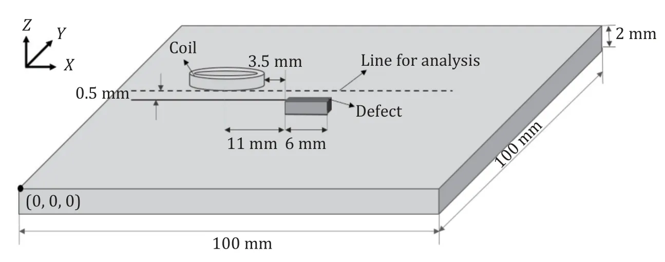
Fig.4.Simulations setup diagram.
Fig.5 (a) displays the amplitude ofBzalong a dotted line under the 30 mA excitation current without any defect,while Fig.5 (b) shows the correspondingBzamplitude in the presence of a defect.It can be seen that the amplitude change is not very significant at 100 kHz,300 kHz,or even 600 kHz,and can only be clearly recorded at 1 MHz.TheBzamplitude reduces at the defect left tip near the excitation coil,and increases at the right tip far away from the excitation coil.Figs.5 (c) and (d) show theBzamplitude under the 100 mA excitation current.Although theBzamplitude change increases,the overall variation pattern is consistent with that under 30 mA excitation current.Therefore,higher excitation frequency is required to better distinguish defects.
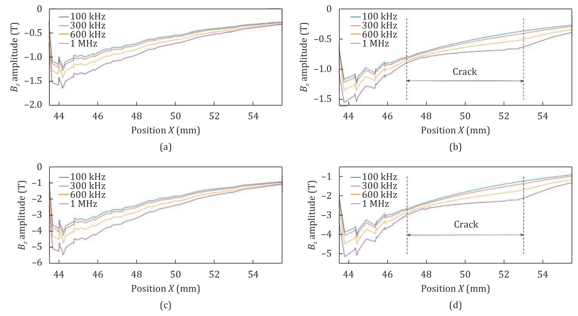
Fig.5.Bz amplitudes along the dotted line: (a) and (c) normal Bz amplitudes under 30 mA and 100 mA excitation;(b) and (d) Bz amplitudes under 30 mA and 100 mA excitation with the defect.

Fig.6.Bz phases along the dotted line: (a) and (c) normal Bz phases under 30 mA and 100 mA excitation; (b) and (d) Bz phases under 30 mA and 100 mA excitation with defect.
In addition to the amplitude,the phase is an important feature that can reflect temporal characteristics.Therefore,the phase variations ofBzare also analyzed as shown in Figs.6 (a) and (b) which correspond to theBzphases along the dotted line with or without the defect under 30 mA excitation,while Figs.6 (c) and(d) correspond to the results under 100 mA excitation.It can be seen that different excitation currents have almost no effect on the distribution of theBzphase.Defects will cause significant phase changes,with a phase decrease at the defect left tip and a maximum phase at the defect right tip.The phase change is related to the frequency.For low frequencies,the more frequencies increase,the more significant the phase change is.To show the change more clearly,50 kHz and 200 kHz are also added to Figs.6 (b) and (d).However,the phase change from 600 kHz to 1 MHz is relatively close.Therefore the phase change no longer increases significantly after reaching a certain frequency.When measuring CFRP defects through the phase,it is necessary to fine tune the frequency to achieve the best measurement effect.For this experiment setup,600 kHz is applied.
In the amplitude detection model,both theBzamplitudes with and without defects gradually decrease in the direction of coil extension.The two patterns are much closer.In order to identify defects,it is necessary to compare the measuredBzamplitude with reference in the absence of defects.In contrast,by utilizing phase measurement,defects can be directly identified through phase changes.Therefore,the phase detection model is more suitable for detecting defects.Moreover,the requirement for magnetic field sensitivity is also reduced,as there is no need to distinguish weaker changes in the magnetic field amplitude.
3.2 Influence of defect position and orientation
The influence of defect position and orientation is further investigated.First,we analyze the case where the defect length direction aligns with the radial direction of the excitation coil,as shown in Fig.4.It often leads to significant disturbance to ECs,which is favorable for detection.Fig.7 (a) is a top view of the EC distribution on the sample surface; the lines with arrows are the excitation currents,the clockwise arrows are ECs,the rectangular box is the defect,and it shows that ECs will increase at both tips of the defect.Fig.7 (b) is theBzphase along the dotted line.On the left side is the phase corresponding to the excitation coil,while further to the right,outside the coil is our measurement region.The EC magnetic field at the defect left tip makes theBzphase decrease faster than that in the normal case and reach the minimum value inside the left inner tip of the defect.On the rightwards,theBzphase gradually recovers due to the reduced influence of the left tip EC magnetic field.Once approaching the right tip,the influence of the right tip EC magnetic field increases.Also,since it is in the opposite direction,the phase continues to increase to obtain the maximum value inside the right inner tip of the defect.Fig.7 (c) is the two-dimensionalBzphase distribution.The rectangle is marked as the defect position.It shows that the defect can be directly imaged through the phase distribution,and the corresponding distribution characteristics can be found.

Fig.7.Simulation results with a 6 mm long defect: (a) EC distribution,(b) Bz phase diagram on the dotted line,and (c) Bz phase image.
Figs.8 (a) and (c) illustrate the top views of the EC distributions in two different experiment settings: One with a defect rotated counterclockwise by 60° around its center and the other with a defect rotated by 90°.Correspondingly,Fig.8 (b) and (d) display the correspondingBzphase images,where the imaging area is a rectangular shape located 1.5 mm outside the coil.The width is 10 mm and the height is 15 mm.In Fig.8 (b),the overall pattern remains consistent with the analysis above,except that the regions of enhancement and weakening rotate in accordance with the defect.In Fig.8 (d),it can be observed that the effects of enhancement and weakening caused by the defect are less pronounced,but the phase decrease within the defect area becomes slower.Consequently,it can be concluded that the detection effectiveness is better when the length direction of the defect aligns with the radial direction of the coil,while it is the poorest when the direction is perpendicular to this orientation.
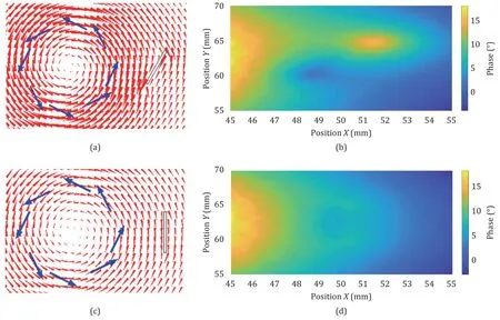
Fig.8.Simulation results for different defect positions and orientations: (a) and (c) top views of the EC distribution of different settings; (b) and (d) corresponding Bz phase images.
4 Experiments
Fig.9 is the PI-ECMO nondestructive testing system developed by our laboratory.It consists of a signal generation system,laser,optical system,lock-in amplifier,2D scanning platform,and imaging system.An EC excitation coil with the same size is used as the simulations.The actual imaging is always within the range from 2 mm to 25 mm at the edges of the coil,which is just in the range ofBzphase decline for the normal case.If there is a defect,theBzphase is supposed to fluctuate,as analyzed above.The T300/3K plain woven carbon fiber boards of 100 mm × 100 mm × 2 mm are used in the following experiments.The width of the fiber bundle is about 2 mm,and the electrical conductivity in the fiber direction is approximately 11000 S/m.Based on the validation of simulations and experiments mentioned above,the optimal parameters for phase imaging are determined.It is found that using an excitation frequency of around 600 kHz yields the best results,and a small excitation current is sufficient.Therefore,an excitation frequency of 600 kHz and an excitation current of 30 mA are applied in this study.The maximum scanning range of the system is 50 mm × 50 mm,with a maximum scanning speed of 10 mm/s.The subsequent detection images are C-scans taken at 0.5 mm intervals and resized 5 times by bicubic interpolation for better visibility.
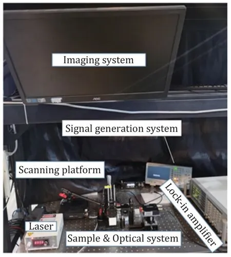
Fig.9.Photograph of the experiment system.
For the measured magnetic induction intensity,due to the absence of standard instruments for weak magnetic field detection,the magnetic induction intensity in the detection area approximately 10 mm outside the coil can be calculated based on the coil size and the applied excitation current.At this distance,the magnetic induction intensity is about 5 μT,and the response is more than 20 times higher than the noise level.Consequently,this detection system is capable of identifying magnetic fields at the microtesla (μT) or even lower.
Fig.10 (a) shows the imaging region (marked with the rectangular box) on the test piece without defects.Fig.10 (b) is theBzphase image corresponding to the test piece.TheBzphase decreases continuously away from the excitation coil,which is consistent with the simulations.
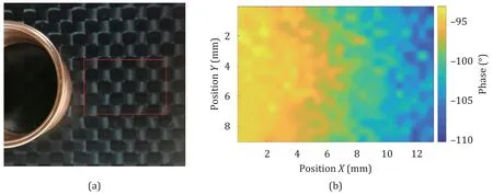
Fig.10.Normal sample under 600 kHz,30 mA excitation: (a) experiment setup with an imaging region in the rectangle box and (b) phase image.
Fig.11 (a) is the CFRP plate containing the crack defect.The imaging region is marked in the rectangular box.The crack is about 6 mm long,2 mm deep,and 1 mm wide.Fig.11 (b) is the correspondingBzphase image,which is consistent with the simulation image shown in Fig.7 (c).The results demonstrate that the PI-ECMO system can detect defects using a 30 mA excitation current,which is much less than several Amperes in traditional ECMO systems [13].

Fig.11.Crack defect sample under 600 kHz,30 mA excitation: (a) experiment setup with an imaging region in the rectangular box and (b) phase image.
Fig.12 (a) is the CFRP plate containing the impact defect.The surface of the test piece is hit by a 1 kg small ball falling from a height of 1 m.The defect is marked in a circle but is hardly recognized visually.Fig.12 (b) is the phase image.The impact will cause the fiber bundles deviating to form large gaps,which influence the phase distribution.From the detection results,it can be observed that the proposed detection system is capable of detecting not only surface defects but also internal defects.
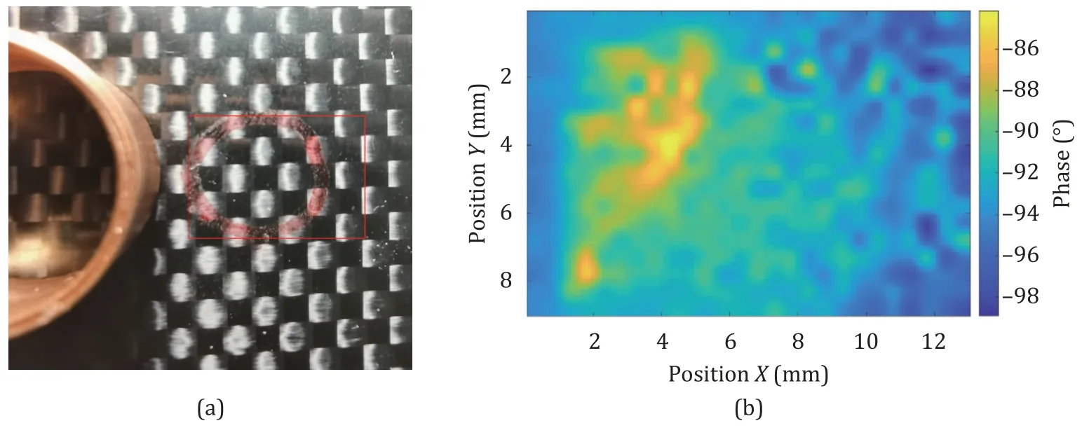
Fig.12.Impact defect sample under 600 kHz,30 mA excitation: (a) experiment setup with an imaging region in the rectangular box and (b) phase image.
5 Conclusion
This article analyzes the vertical magnetic field (Bz) variation on CFRP specimen surfaces under fixed position pancake coil excitation.Furthermore,a highly sensitive PI-ECMO imaging detection system is developed for defect detection in CFRP.Based on the theoretical analysis and experiments,the following conclusions can be drawn:
1) Under fixed position EC excitation,the changes in theBzphase caused by the defects are more significant than the changes in the amplitude at lower frequencies and with smaller excitation currents.Therefore,Bzphase imaging is more suitable for detecting woven CFRP defects without increasing the excitation amplitude and frequency.
2) The PI-ECMO imaging detection system demonstrates higher sensitivity in detecting defects aligned with the coil radial direction.The sensitivity for detecting defects in the vertical orientation is significantly reduced,but it can be addressed in practice by adjusting the excitation position.
3) The proposed PI-ECMO system employs various methods to enhance sensitivity,including optimizing the optical path structure and utilizing an auto-balanced photodetector and lock-in amplifier.These enhancements enable the system to effectively detect processed crack defects and irregular impact defects.And the used excitation current is significantly reduced compared with traditional ECMO systems.
The analysis and validation presented in this article are not limited to the mechanical scanning system.In the future,we will carry out research on more efficient PI-ECMO techniques for CFRP defect detection,such as the optical scanning method.
Funding
This work was supported by the National Natural Science Foundation of China under Grants No.U2030205,No.62003075,No.61903065,and No.62 003074; Sichuan Science and Technology Planning Project under Grant No.2022JDJQ0040.
Declaration of competing interest
The authors declare no conflicts of interest.
杂志排行
Journal of Electronic Science and Technology的其它文章
- Developing microwave-induced thermoacoustic tomography: System,application,and reconstruction
- Life-cycle assessment of batteries for peak demand reduction
- Low working loss Si/4H-SiC heterojunction MOSFET with analysis of the gate-controlled tunneling effect
- Algorithms for automatic measurement of SIS-type hysteretic underdamped Josephson junction’s parameters by current-voltage characteristics
- Boundedness and liveness enforcement for labeled Petri nets using transition priority
- Characteristics of sub-synchronous oscillation in grid-connected wind farm system
