PT-symmetric electronic dimer without gain material
2023-12-06SenghorTagouegniFernandeFotsaNgaffoandAurlienKenfackJiotsa
Senghor Tagouegni,Fernande Fotsa-Ngaffo and Aurélien Kenfack-Jiotsa
1 Laboratory of Mechanics,Materials and Structures,Department of Physics,Faculty of Science,University of Yaounde I,PO Box 812,Yaounde,Cameroon
2 Nonlinear Physics and Complex Systems Group,Department of Physics,The Higher Teacher’s Training College,University of Yaounde I,PO Box 47 Yaounde,Cameroon
3 Institute of Wood Technologies,University of Yaounde I,PO Box 306,Mbalmayo,Cameroon
Abstract In this paper,a way of building an electronic Parity Time (PT)-symmetric dimer without gain material is presented.This is achieved by capacitively coupling a pair of LZC circuits,each combining an inductance L,an imaginary resistance Z and a positive/negative capacitance C.We derive the effective Hamiltonian of the system,which commutes with the joint PT operator.The eigenspectrum displays spontaneous breaking points,where the system undergoes a transition from real to complex values.The transition points are imposed by the range value of the coupling thanks to the use of a negative capacitance.Temporal charge solutions and energy propagation are also analytically and numerically investigated,and the results are compatible.In the exact phase,these quantities oscillate,whereas in the broken phase,oscillations disappear,giving place to amplification.Our results pave the way to innovative PT -symmetric circuits.Applications could include,among others,optics,metamaterials,photonics and sensitive detection.
Keywords: negative capacitance,parity-time (PT) symmetry,imaginary resistance
1.Introduction
Hermiticity is a fundamental postulate in Quantum Mechanics that guarantees for an operator Hamiltonian H,real eigenvalues representing the energies of a system.Whenever open systems interact with the external environment,they are described by non-Hermitian Hamiltonians for which the energy spectrum is complex in general.Among non-Hermitian Hamiltonians,it belongs to those that are invariant under the joint transformations of spatial reflection (parity P)and temporal inversion (time-reversal T) which may admit real eigenvalues.This particular class of Hamiltonians,called PT -symmetric Hamiltonians,was first introduced in Quantum Mechanics in 1998 by Carl Bender and Stephan Boettcher[1],before rapidly spreading to other branches of physics as optics [2–5],photonics [4,6],mechanics [7–10] and electronics [11–15],to mention a few.PT -symmetric Hamiltonians generally require that gain and loss into the system should be balanced,so that,as the degree of non-Hermiticity (also called gain/loss parameter) is increased,the system exhibits a transition from PT exact phase with real frequencies to PT broken phase,where the frequencies become complex.In particular,electronics PT -symmetric circuits have received a lot of attention in recent years,due to their experimental simplicity.These circuits have mostly consisted in coupling a pair of active LRC circuits [11,13],one with amplification (gain) introduced by the negative resistance -R,and the other with an equivalent amount of attenuation (loss) inherent to the positive real resistance +R.As the gain/loss parameter of the system,namely γ varies,two transition phases are observed in the eigenvalues: from real to complex and from complex to pure imaginary values.The eigenvalues and their corresponding eigenvectors coalesce at a singular parameter space of the system,known as the exceptional point (EP) [16].In general,the PT exact phase is also noticed as the domain of periodic solutions characterized by the Rabi power oscillations.On the contrary,the PT broken phase exhibits uncontrolled growth or decays solutions [17].Recently,the manipulation of electronic components with a purely imaginary impedance Z [18–20]has developed great interest.The imaginary resistance Z=jr(because that is what it is all about),does not dissipate/amplify the energy like a real resistance +/-R.Its main characteristic is the ability to generate frequency independent phase shift,unlike inductor/capacitor reactive elements,which can only do this task when they are associated with a nonzero frequency [20].Indeed,it was proven that it can validly replace an inductance L,so that the first order resonance oscillator ZRC can be proposed to substitute the conventional second order resonance oscillator LRC [15,21–23].The use of the imaginary resistance allows efficient manipulation of higher and smaller positive/negative frequencies.Hence,innovative imaginary resistance based PT -symmetric circuits have been studied [15,22].Interestingly,it was demonstrated that the ZRC dimer may be PT transitionless normal mode spectrum,i.e.without phase transition and exceptional points,when using essentially negative values of capacitors.This allows the system to be conservative regardless of the gain/loss values,giving the possibility to generate higher frequencies in normal modes which induce a large PT -symmetric phase and a large bandwidth [22].Despite the flexibility of the imaginary resistor to react with other positive and negative components,its combination with inductors and capacitors within the same cell remains unexplored.To the best of our knowledge,no PT -symmetric system has been developed to date in electronics without taking into account negative resistors.
The main objective of this study is twofold.First,it is to demonstrate that a pair of coupledL i Z i Ci(i=1,2)linear circuits built without gain material as a negative resistor,in which the capacitance values have both positive and negative signs,can exhibit a PT -symmetry.In other words,our work offers the benefit of obviating the requirement for materials with gain and loss characteristics,such that a PT phase transition pattern is dictated by capacitive and imaginary resistive parameters.In addition,we show that the dynamic evolution of the real charge and relative intensities are in accordance with the PT phase transitions.
The text is organized as follows: section 2 presents the electronic circuit model as a typical non-Hermitian system.The next section provides the eigenvalues analysis.This will be followed by section 4,where we investigate both analytical and numerical charge capacitors and the energies in the system.Finally,the main conclusions are presented in section 5.
2.Model description
The proposed PT -symmetric dimer is schematically shown in fgiure 1.It consists of a pair ofL i Z i Ci(i=1,2)linear circuits,all made of an inductance Li,an imaginary resistance Zi=jri(j is the imaginary unit) and a capacitance Cicoupled through a ZC series combination (where Z=jr).It is also worth noting that only the capacitive C or the imaginary resistive Z coupling can be activated at the same time.Apart from the inductances which are absolutely positive,capacitances and imaginary resistances can be taken as positive or negative.Several ways for implementing the imaginary resistance were proposed in the literature [18–20].Direct realizations are based on transformers or balanced three phase systems [18,19],while indirect ways are based on gyrators [20].According to its impedance expression Zi=jri,it is obvious that an imaginary resistance does not make power or energy dissipation as usual resistances.Indeed,it can be demonstrated that it has the inductive property when ri>0 and the capacitive property ri<0.This can,therefore,be regarded as a kind of reactance element [18].The realization of electronics PT -symmetric dimer structures requires active LRC circuits,one with a negative resistance(-R) providing the energy income (gain cell) [11–13],and the other with a positive resistance of identical value (+R),accounting for the energy losses (loss cell).It becomes evident that the proposed model differs from the standard PT circuits built with real resistances since in this system,no cell obviously plays the role of gain or loss.
By applying the Kirchoff laws,the circuit equations are straightforward:
Applying the PT operator where the parity P and the time T operators respectively read as [12]:
with σxbeing the first Pauli matrix,I2the 2 × 2 identity matrix and K the complex conjugate operation,it is easy to verify that the Hamiltonian Heffis PT -symmetric (that is to say Heffand PT are commutative [Heff,PT] =0),if the following conditions are fulfilled:
Hence,the corresponding eigenfrequencies ωi,solutions of equation (10) can be obtained in unit of ω0as:
where the two breaking values βcr1,2known as the EPs [16]are respectively obtained as:
3.Eigenvalues analysis
Equation (11) reveals four eigenfrequencies grouped in two pairs ω1,2and ω3,4all displaying the characteristic behaviorω∝±a generic feature of the PT -symmetry breaking [13].A quick analysis of this eigen equation indicates that one of the frequency pairs is PT transitionless mode and remains completely real for a given value of the coupling c,whereas the other frequency pair is characterized by PT phases transitions,occurring at the breaking values βcr.Hence,the dynamic of the entirely spectrum can be described by the behavior of this later frequency pair.In our model the breaking values evolution is dictated in general by the value of the active coupling in place,the range of the capacitive coupling c in particular.Table 1 summarizes the different possible combinations of the circuit capacitive elements to have the range of positive or negative values of c.The experimental realization of the negative capacitance can be found in [24–26].
Table 1.Combination of circuit capacitive elements for either positive or negative coupling parameter c,where c (C ≠-C0).

Table 1.Combination of circuit capacitive elements for either positive or negative coupling parameter c,where c (C ≠-C0).
Indeed,when c >1,which is only possible thanks to the combination of positive and negative capacitances [22,24–26],the spectrum follows the first frequency pair ω1,2behavior of which breaking points EP1 and EP2 are obtained from the first equation of (12) respectively asβcr1-=andβcr1+=These points are symmetrical with respect to zero coupling.However,when c <-1,the eigenspectrum follows behavior of a second frequency pair ω3,4,with the breaking points EP3 and EP4 also found from the second equation of (12) as βcr2-=–2γand βcr2+=–2γ+Remarkably,in the absence of the imaginary resistive coupling (γ=0),these later breaking points are symmetrical with respect to zero.For c taken between -1 and 1,the breaking points have purely imaginary or complex values,implying a zero real transition.Therefore,the eigenspectrum is completely real.In figure 2,we have plotted in 3D,the real (a) and the imaginary(b) parts of the modes frequencies ωi,as a function of the capacitive coupling c and the aforementioned non-Hermitian β parameter.The plots are obtained when the two couplings are activated,the imaginary resistive coupling being constant γ=0.2 and remains unchanged throughout the paper unless otherwise specified.It is shown from the figure as we said above that the eigenspectrum dynamic entirely depends to the range value of the capacitive coupling c.One frequency pair is in transitionless mode and comes into real values,whereas the other allows phase transitions from the real to the complex domain as β parameter is changing.This behavior is similar to what happens in conventional LRC circuits with PT -symmetry,which usually exhibit two breaking points,and then allow transitions from real to complex and from complex to purely imaginary frequencies [11–13].To argue the above analysis,a cross-section of figure 2 is realized in figure 3,for different values of the coupling parameter c.The real (solid lines) and the imaginary (dashed line) parts of the frequency pairs ω1,2and ω3,4are respectively shown with the blue and red colors.As we can see in figure 3(a) when c >1,for example c=5,only ω1,2admit two symmetrical EPs,EP1 and EP2 corresponding to critical values βcr1-=-4 and βcr1+=4,respectively.In the meantime,a frequency pair ω3,4remains entirely real as β is varying.Therefore,for the entirely eigenspectrum,EP1 and EP2 separate the regions of real frequencies (PT exact or unbroken phase) from that of complex frequencies (PT broken phase) which is then comprised between the two breaking points.
In figure 3(b) for c <-1,for example c=-3,the previous behavior is also observed,since both frequency pairs interchange their behavior.Indeed,ω1,2becomes entirely real,while ω3,4exhibit two EPs,EP3 and EP4 occurring at βcr2-=-3.22 and βcr2+=2.42,respectively,thus separating PT exact phases from the broken one.For the cases of coupling c taken between -1 and 1,as illustrated respectively in figure 3(c) with c=0.75 and in figure 3(d) with c=-0.5,it is seen as expected that the eigenspectrum remains entirely real.So,in this coupling range,the PT -symmetry of the system is broken,leading to a Hermitian behavior.Therefore,the system generates higher frequencies for potential applications in the fields of photonics,optics,sensitive detection and telecommunication.Another cross-section of figure 2 is made in figure 4 and favors the analysis of the eigenspectrum when the aforementioned non-Hermitian parameter β is fixed.As can be seen in the figure,where the real (solid) and the imaginary (dashed) parts of the modes frequencies are reported as a function of c for β=-4,each frequency pair exhibits a breaking point separating the exact to the broken phase.At the breaking point,the coupling c takes critical values ccr1,2expressed in equation (13).It is noticed that the value of ccr1remains always positive and occurs where the frequencies ω1and ω2coalesce,whereas ccr2is rather negative corresponding to the coalescing of ω3and ω4
As we can see in the figure,for c <ccr1=5,the frequencies ω1,2are real.They become complex when c >ccr1.The same applies to the frequencies ω3,4which are real for c >ccr2=-4.24,and complex when c <ccr2.Hence,the entire spectrum is in the PT broken phase if the capacitive coupling obeys c <-4.24 and c >5,whereas the PT exact phase corresponds to c taken between -4.24 and 5.
·Particular case: aPT-thresholdless(THL)dimer
As it was shown in [13] for an MLC PT dimer made of multiple couplings that includes a capacitive coupling,it can be demonstrated that our system admits a zero breaking point,i.e.βcr1,2=0,if the capacitive coupling obeys the following thresholdless conditions:
For the particular value c=c1=1,which corresponds to the first thresholdless condition (see equation (14)),whatever γ,it can be seen from figure 5(a) that,as one would expect,the EPs EP1 and EP2 obtained for example in the case c=5 (figure 3(a)) with the frequency pair ω1,2vanish.Hence,the PT broken phase disappears and the system directly enters PT exact phase where the spectrum becomes entirely real as in the Hermitian case.A similar scenario occurs in figures 5(b) and(c) obtained when the coupling obeys to the second thresholdless condition (see equation (14)),i.e.c=-1.04.It is there remarked that EP4 and EP3 disappear,since the threshold values βcr2+and βcr2-become zero for γ=0.2 and γ=-0.2,respectively,as ∣β∣ increases starting from 0.In the other particular case, c=0 (only the imaginary resistive coupling is active) which is not shown in the figure,equation (12) indicates that the breaking values are not real so that the spectrum remains real everywhere.These results differ from those found in [13],where it was established that the thresholdless point (THLP) allows the system to enter the PT broken phase instead of the PT exact phase.THLP PT -symmetric systems can offer intriguing properties,such as the ability to control prohibited waves in the linear regime [13],allangle supercollimation,the superprism effect and single-mode laser emission in microrings [27].In the following,we will use the THLP in oscillations control,in the PT exact phase.
4.Exact solutions
To investigate the dynamic evolution of the real charge capacitor and relative intensities of the oscillations in the proposed PT dimer system,we must solve the equation (1)analytically and numerically using the Runge Kutta fourth order algorithm.Before doing so,let us first look at the specific case of the single LZC circuit in absence of the coupling.The dimensionless equation for the charge capacitor in the cell is given by:
where τ=ω0t is the dimensionless time.Then,taking an anzatz q=q0ejωτ,the charge solutions oscillate according to:
whereψ(0)is the initial condition,and Heffis the effective Hamiltonian of the system,written as in equation (5).Taking into account the PT -symmetric conditions (8),the above solution is entirely obtained by the eigenanalysis of the matrix Heff,whose independent eigenvectorsvki(1 ≤k≤4)are associated with the eigenvaluesωi(1 ≤i≤ 4),i.e.the eigenpairs (ωi,vki).Then,the general solution (17) can be rewritten using the Jordan canonical form [28] as:
where ωiare found in equation (11) and λkare the constants of integration.These constants can be found setting t=0 in the previous display,which gives:
withψ(0)=(q1(0)q2(0).In such a way,the expressions of the chargesqi(t)(i=1,2)through the PT dimer can be calculated analytically.
From the expression of charge solutions obtained in equation (18),the intensities are calculated as:
Therefore,the relative intensities aican be deduced from equation (20):
Equation (1) can be also solved numerically.In this way,the normalized charges capacitor qi(τ) and relative intensities ai(τ),(i=1,2) of the oscillating wave can be investigated both analytically and numerically.From the foregoing,we have seen that no distinction can be made between the two parts of the system (since no cell is obviously gain or loss).For this reason,there is any singularity to introduce the signal from the left or from the right cell of the dimer as usual.The system is then insensitive to the side of the initial input.To explore the propagation dynamic,in the following,the initial conditions are set for example as q1(0)=0,q2(0)=1,assuming all other dynamical variables zero=0).We show that the PT -symmetry fingerprint is reflected in the propagation behavior through the dimer.
As illustrated from figures 7–9,the analytical solutions(circular points) are in perfect agreement with the numerical results (solid and dashed curves) based on the original equation (1).Hereafter,the blue and the red colors refer to the subindex i=1 and i=2,respectively.From figures 7(a)–(d),the temporal evolution of the charge capacitor qithrough the dimer is plotted depending on whether the aforementioned non-Hermitian parameter β is taken from different PT regimes exhibited in figure 3,when c=5 and γ=0.2.In figures 7(a) and (c) for example when β=1,corresponding to the PT broken phase,the eigenvalues of the system are complex.It is shown that the real charges q1,2grow exponentially with the dimensionless time parameter τ.This behavior is also perceptible in the inset (i) of figure 7(a) where it is also noted an exponentially decreasing of charge when c is negative (c=-5).However,in figures 7(b) and (d) when β=35,the system is in the PT exact phase since the eigenfrequencies are real.Then,the charges oscillate periodically between the two cells.These observations are well confirmed by the plots in figures 7(e) and (f) illustrating the relative intensity ai(τ).As we can see in figure 7(e),in the broken phase,once a signal is put into the cell i=2,it is noticed a short and rapid exchange of energy between both cells for which the energy does not take long to grow exponentially to an infinite value.This allows the relative intensity to turn linearly toward the constant value 0.5(ai→0.5).On the contrary,in figure 7(f) where the system is in the PT exact phase,it is also noticed a rapid periodic exchange of energy between the two circuits,allowing the transfer of energy from one cell to the other.This is made in an oscillatory process during the time,so that when the energy of one cell reaches its maximum value,the one of the other remains closed to zero.These descriptions are in perfect accordance with the behavior observed with LRC based electronic PT dimers [12] and optical beams [29].
When c=-0.5,it is clear as we have seen from figure 3(d) that the system frequencies remain real for any value of the parameter β.Using this coupling value,in figures 8(a)–(c),the real charges dynamic and the relative intensity are respectively plotted for example for the value β=10,and the results perfectly match with the comments made above.There is a periodic exchange of real charges (q1,2),and the energy(a1,2) well oscillates between the two cells of the dimer.The above results open up to various applications using the negative capacitances.In figure 9,we analyze the real charges dynamic and the relative intensities,following the same logic used to obtain the figure 5,where the aforementioned non-Hermitian parameter is fixed to β=-4 and the coupling c is the dynamic parameter.As we expected,when c=4.99 (first column) corresponding to the PT exact phase,Rabi oscillations are observed between the charges of the two dimer cells (figures 9(a) and (c)),and the relative intensities perfectly oscillate around the equilibrium value of 0.5 (figure 9(e)),meaning a conservation of the energy.However,when c=5 which corresponds to a PT breaking value,we noticed amplified oscillations of the charges capacitor (figures 9(b)and (d)).In the meantime,the relative intensity plot indicates that the energy oscillations vanish at the time as the system begins to enter the broken phase (figure 9(f)).
·Solutions at the thresholdless point(THLP)
As we have seen above,at the THLP,the system is entirely in the exact phase,characterized by real frequencies and the Rabi oscillations.Figure 10 shows the temporal evolution of the charges and the relative energy of each dimer cell,corresponding to the two THLPs mentioned above,i.e.c=1(first and second column) and c=-1.04 (third column),when fixing β=20.We intend here to demonstrate that the THLP can be used to control oscillations of charges and energy in the system.To do so,we apply distinct initial conditions to the system when setting it at the THLP.Looking at the curves,the first impression is that the THLP is very sensitive to the initial input signal.The second is that,at the THLP,the system is robust in terms of charge distribution.So,a number of fascinating behaviors can be observed.Indeed,in figure 9(a),considering the initial condition q1(0)=1/4,q2(0)=3/4 (first column),we can see that the charge is evenly distributed between the two extreme values 0.25 and 0.75,corresponding to the amplitudes of the input signal.One of the cells is fully discharged while the other is charged and vice versa,compared to what is observed in figures 7(b),8(a) and 9(a),where the amplitudes of charge oscillations can vary.As for the relative intensity,it oscillates regularly (see figure 10(b)).In figure 10(c),when the initial signal is injected in equitable proportions into the two cells,i.e.q1(0)=q2(0)=(second column),we note that the charge and energy stop oscillating as if,the two cells were not coupled.Then it seems the system no longer reacts to the excitation,and no oscillation is perceptible.In the case where oscillations do occur (for example,if c=-1.04 which is not shown in the figure),the same time behavior is exhibited for both cells.As a result,in all cases,there is no master or slave cell in the system.In figure 10(c),for c=-1.04 considering the initial condition q1(0)=0,q2(0)=1,we notice that the master cell (the one receiving the excitation,i.e.here the cell i=2),obliges the other cell (i.e.slave cell i=1) to oscillate around negative values as if the two were not related and in this case,the responses of both oscillators are in phase.The relative intensity plot clearly shows free and regular oscillations.

Figure 1.The PT -symmetric dimer without gain material in which two L i Z i Ci (i =1,2)linear circuits are coupled by an imaginary resistance and a capacitor.
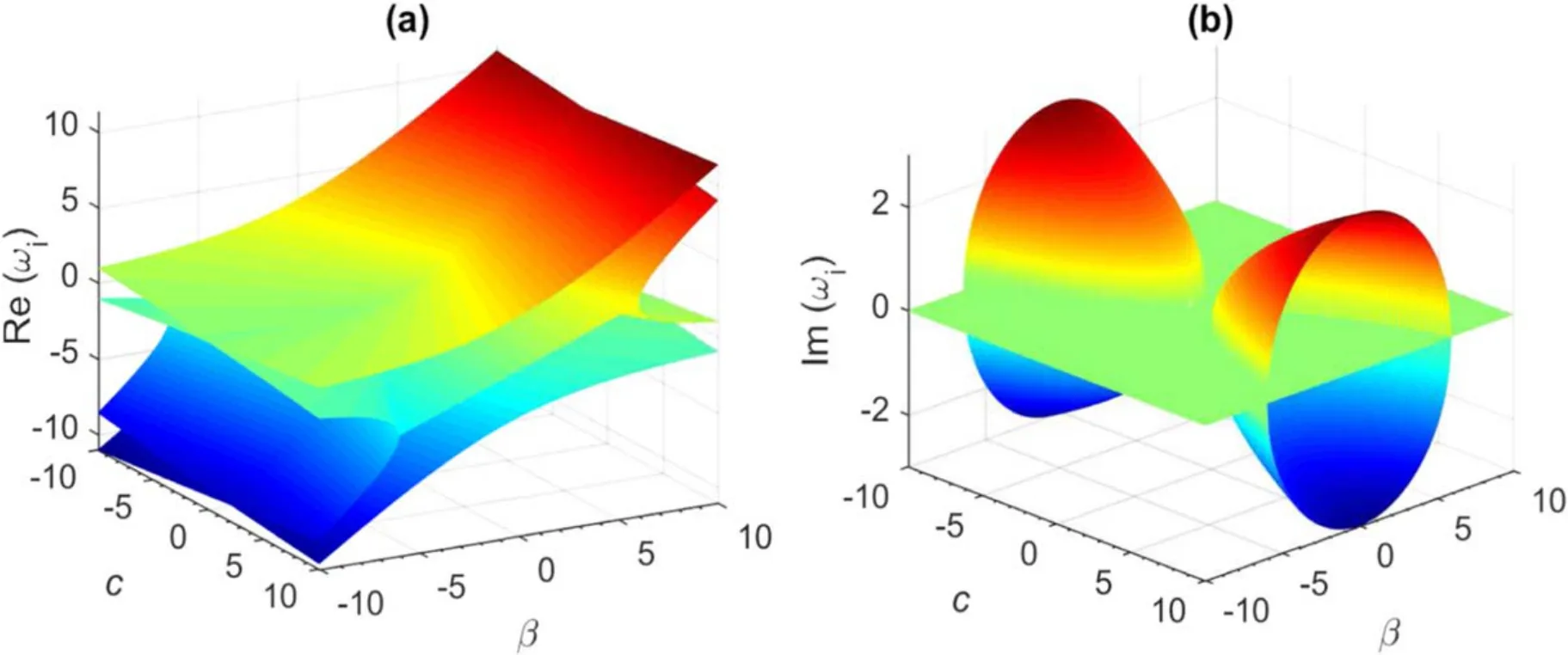
Figure 2.Real (a) and imaginary (b) parts of system eigenfrequencies ωi (i=1,2,3,4) as a function of c and β parameters,for γ=0.2.
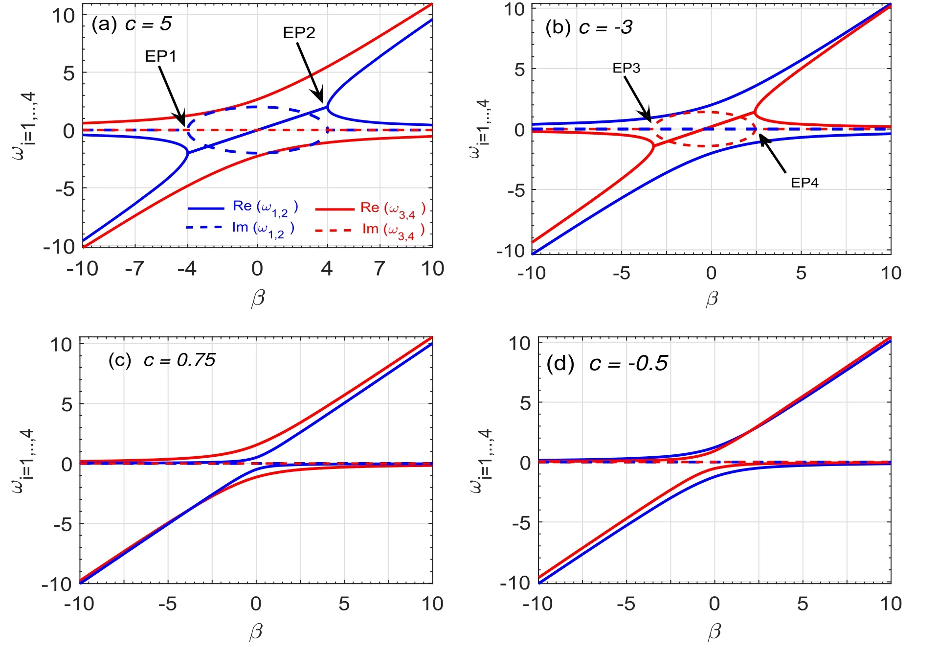
Figure 3.Real (solid) and imaginary (dash) parts of system eigenfrequencies ω1,2 (blue color) and ω3,4 (red color) as a function of β parameter for different values of c,when γ=0.2.In (a) c=5 >1,(b) c=-3 <-1,(c) -1 <c=0.75 <1 and (d) -1 <c=-0.5 <1.

Figure 4.Real (solid) and imaginary (dashed) parts of system eigenfrequencies ω1,2 (blue) and ω3,4 (red) as a function of coupling parameter c,when β=-4 and γ=0.2.

Figure 5.Real (solid) and Imaginary (dash) parts of system eigenfrequencies ω1,2 (blue color) and ω3,4 (red color) as a function of β parameter for different values of c corresponding to the thresholdless point.(a) c=c1=1,γ=0.2.(b) c=c2=-1.04,γ=0.2 and (c)c=c2=-1.04,γ=-0.2.
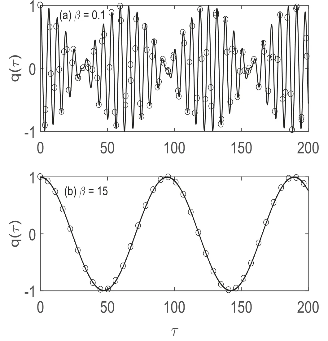
Figure 6.The real charge capacitor q(τ) dynamic across the LZC cell for the initial condition q(0)=1 and =0.The solid lines correspond to the numerical solutions,and the circular points are the corresponding analytical results.(a) β=0.1;(b) β=15.
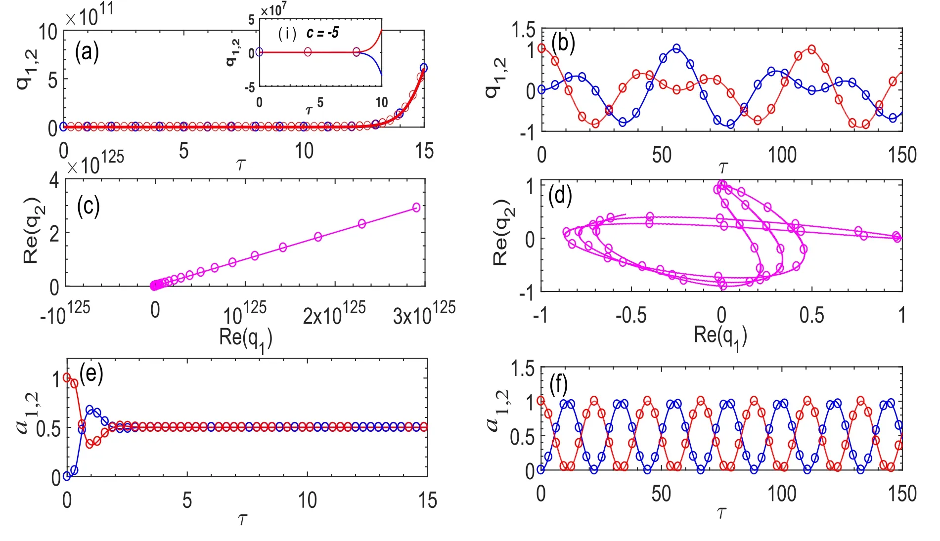
Figure 7.(a)–(d): the real charge capacitor qi dynamic across the cells and (e)–(f): relative intensity evolution ai of the two cells,for q2(0)=1, q1 ( 0)===0when c=5 and γ=0.2.The solid (blue) lines correspond to the numerical solutions for the cell number i=1 and the dashed (red) lines indicate solutions for the cell i=2.The circular points are the corresponding analytical results.The first column is obtained for β in the PT broken regime (β=1),while the second column corresponds to the PT exact phase (β=35).
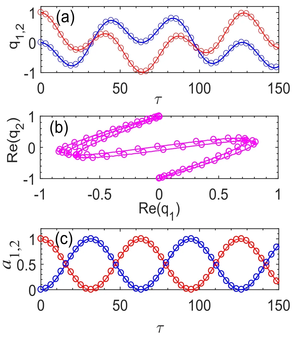
Figure 8.(a),(b): the real charge capacitor qi dynamic across the cells and (c): relative intensity evolution ai of the two cells,for q2(0)=1,q1 (0)===0,when β=10,c=-0.5 and γ=0.2.The solid (blue) lines correspond to the numerical solutions for the cell number i=1 and the dashed (red) lines indicate solutions for the cell i=2.The circular points are the corresponding analytical results.
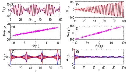
Figure 9.(a)–(d): the real charge capacitor qi dynamic across the cells and (e)–(f): relative intensity evolution ai of the two cells,for q2(0)=1, q1 (0)===0,when β=-4 and γ=0.2.The solid (blue) lines correspond to the numerical solutions for the cell number i=1 and the dashed (red) lines indicate solutions for the cell i=2.The circular points are the corresponding analytical results.The first column is obtained for β in the PT -symmetry regime (c=4.99),while the second column corresponds to the PT breaking point (c=5).

Figure 10.The real charge capacitor qi dynamic across the cells (a),(c) and (e) and the relative intensity evolution ai of the two cells (b),(d)and (f) for the PT dimer at the different THLP and for different initial conditions: c=1,q1(0)=1/4,q2(0)=3/4 (first column);c=1,q1 (0)=q2(0)=(second column) and c=-1.04,q1(0)=0,q2(0)=1.The other parameters are ==0,γ=0.2 and β=20.The solid (blue) lines correspond to the numerical solutions for the cell number i=1 and the dashed (red) lines indicate solutions for the cell i=2.The circular points are the corresponding analytical results.
5.Conclusion
In summary,we have demonstrated that a pair of coupled LZC circuits,which do not require gain material as in conventional LRC circuits,can exhibit a PT -symmetry.We have determined for the system four eigenvalues,grouped in two pairs,one of which is PT transitionless mode and the other exhibits the PT breaking points whose dynamic is essentially dictated by the capacitive coupling c.We have also analytically and numerically investigated the propagation dynamic in the proposed PT dimer system,and the results of both studies match perfectly.In the PT exact phase,we have noticed Rabi oscillations in the real charges and periodic exchange of the energy between the two dimer cells.At the PT breaking value,the charges and energy linearly increase,whereas in the PT broken phase,this increase is made in an exponential form,in comparison to the behavior observed with traditional PT -symmetric circuits.Our study opens avenues for innovative electronics architecture of PT -symmetric circuits and suggests applications with negative capacitors and imaginary components.
Acknowledgments
We acknowledge Dr Emmanuel Fendzi Donfack for helpful discussions and Pr Aloysius Ngefac for proofreading the paper.
ORCID iDs
杂志排行
Communications in Theoretical Physics的其它文章
- Graphical representations and worm algorithms for the O(N) spin model
- Insight into the magnetic behavior and magnetocaloric effect of a borophene monolayer
- Flocking and clustering in mixtures of selfpropelled particles with or without active reorientation
- Vibrational resonance in a multistable system with position-dependent mass
- Nonequilibrium kinetics effects in Richtmyer–Meshkov instability and reshock processes
- AC magnetic trap for cold paramagnetic molecules
