Structure study of a dielectric laser accelerator with discrete translational symmetry
2023-12-02YangfanHe何阳帆BinSun孙斌MingjiangMa马铭江WeiLi李伟ZhihaoCui崔志浩andZongqingZhao赵宗清
Yangfan He(何阳帆), Bin Sun(孙斌), Mingjiang Ma(马铭江), Wei Li(李伟),Zhihao Cui(崔志浩), and Zongqing Zhao(赵宗清)
1Laser Fusion Research Center,CAEP,Mianyang 621900,China
2The Sciences and Technology on Plasma Physics Laboratory,CAEP,Mianyang 621900,China
3University of Science and Technology of China,Hefei 230026,China
4The Institute of Optics,University of Rochester,Rochester,NY 14627,USA
Keywords: dielectric laser accelerator,acceleration structure,high-gradient accelerator
1.Introduction
Particle accelerators play a crucial role in fundamental science, as well as in various practical applications such as cancer treatment, materials analysis and food and water purification.[1–4]Traditional accelerators use radio-frequency klystrons to excite modes in copper or superconducting niobium cavities for particle acceleration,but their large size,high power requirements and expensive infrastructure limit their accessibility to the broader scientific community.This has promoted the exploration of more compact and economical alternative technologies.
With the advancement of microfabrication and laser technology, many ideas have been practically implemented, such as the use of terahertz interaction with microstructures to accelerate charged particles,[5]ultra-intense ultrafast lasers to interact with plasma for particle acceleration[6,7]and high fields in ultrafast pulsed laser beams to accelerate electron beams in dielectric microstructures.[8]In general, the acceleration gradient determines the total length of the accelerator at a specific beam energy.Therefore,in the process of developing advanced compact accelerators, acceleration techniques should achieve high energy gain per unit length.Recently, dielectric laser accelerators (DLAs) have attracted significant interest as a means of accelerating charged particles using solid-state lasers.[9–16]In various experiments,an acceleration gradient of nearly 1 GV·m-1has been achieved(see Ref.[17]and the references therein).DLAs are promising candidates for realizing future compact and low-cost particle accelerators due to their high energy gain per unit length,which is second only to that of laser-plasma accelerators.[18–24]In addition,DLAs have the advantage of easy integration of cascade acceleration.[25–27]
The design of effective micro/nano dielectric structures to generate accelerating fields driven by input lasers is a critical research topic for DLAs.There are various explanations for the acceleration principle of DLAs, including the phase modulation principle proposed by Plettneret al.,[28]and the analysis of accelerating field mode by Breueret al.[29]for single and double gratings.Aimidulaet al.[30]found that an asymmetric double grating structure can synchronize the laser field with relativistic electrons.Niedermayeret al.[31]used a Fourier transform and the Panofsky–Wenzel theorem to model grating accelerators.Koz´aket al.[32]studied the interaction between evanescent waves and electrons using classical approximation, while Liuet al.[33]studied the field distribution in the accelerating cavity using classical electrodynamics.A comprehensive theory of the Lorentz force in a double grating medium laser accelerator was proposed by Blacket al.[34]The phase modulation principle proposed in these references is commonly used in the design of DLAs (see Ref.[28] and citations therein).It is worth noting that the phase modulation principle used in the design of DLAs is based on geometrical optics.The concept that DLA achieves acceleration when the particle experiences a zero-frequency electric field inspired this study.The physical analogy can be likened to a particle riding a fixed-phase acceleration in the accelerating field.
In this study, we have developed rules for efficient particle acceleration using dielectric structures based on the fundamental equations of electromagnetism.This paper is organized as follows.In Section 2, we elaborate on the rules for efficient particle acceleration with dielectric structures using basic equations.In Section 3, we show the modeling process of the dielectric accelerator in the finite-difference frequency domain (FDFD) in detail.In Section 4, we validate the simplified formula for calculating energy gain,design DLA structures with different parameters and calculate the acceleration gradient using three different materials.
2.Structures and principles
Our starting point,naturally,is Maxwell’s equations in SI units[35]
whereEis electric field,ρis the free charge density,His the magnetic field,Jis the free current density,µis the permeability of the material andεis the dielectric function.All of these are potentially functions of both the positionrand the timet.In this paper, we work with non-magnetic materials,µ=µ0(permeability of free space).The input energy for acceleration is achieved by applying an electric field.We assume the electron is suitably ‘beam-like’ such thatβx ≈β=v/c,
wherevis the velocity of the particle.So, the rate of change of energy can be described by
whereqis the charge of the particle,γis the Lorentz factor,mpc2is the rest mass of the particle andEpxhere is the electric field felt by the particles.

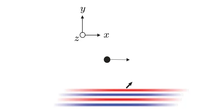
Fig.1.The charged particles in a vacuum interact with the plane wave.In this study,we consider a vacuum as a medium with continuous translational symmetry.
The mathematical form ofEpxcan be artificially designed to be very complex.Fortunately,mathematical theorems guarantee that any electromagnetic field can be decomposed into a superposition of several sine waves via the Fourier transform.This is physically equivalent to the interaction between a plane wave and an electron in a vacuum.In free space,as shown in Fig.1,Epxis an oscillating electromagnetic field
whereδis the initial phase of particle injection,E0is a constant,ωis the frequency of the incident light,kis the wavevector(herek=2π/λ,whereλis the wavelength of the incident light).In a period, it can be assumed that the particles move along a straight line,zp=z0in Eq.(3), wherez0is the initial injection point of the particle in thez-direction.It can be seen that the rate of change of energy of the particle increases and decreases alternately at the frequencyωby combining Eqs.(2)and(3).In other words,the net energy gain of the interaction between a charged particle and an oscillating electromagnetic field is zero, because the odd trigonometric function with time-dependent terms in the expression for electric field experienced by the particle(such asEpxin Eq.(3))is zero on average over a period.Therefore, to achieve acceleration without dephasing,the odd-order trigonometric function should have no time term or not depend onx.To achieve effective acceleration means that particles(from their reference frame)experience a“zero-frequency”electric field.

Fig.2.(a) The cylindrical medium is arranged periodically in the xdirection.(b) The cuboid medium is arranged periodically in the xdirection.It should be noted that the laser can also be incident in the y-direction.The theoretical description in this paper is equally applicable to this situation.The only difference is that a three-dimensional simulation is required.
We note that in the expression describing the electric field experienced by the particle,tshould be treated as an implicit function of the path length along the accelerator (x).This treatment revealed a very natural way to construct the “zerofrequency”electric field felt by particles,which is to use some kind of structure to break the translational symmetry of free space,as shown in Fig.2,

whereGis the inverse lattice vector of the reciprocal space.Without loss of generality,discrete periodicity is introduced in the direction of particle motion(T=Λex).Because the fundamental features of DLA appear in the simplified 2D analysis,the full-field variation withzis not considered for the time being.This means∂E/∂z=0 and∂H/∂z=0.We apply Eq.(6)to obtain

To calculate the motion of electrons in a short DLA,it is usually safe to assume that the electrons are very rigid,so they do not deviate from the trajectory they were on before the DLA.In Eq.(7),tshould be seen as an implicit function of the path lengthx=vt-lalong the accelerator.The phase shift between laser phase and particle injection phase is described by the distancel.We can obtain an expression for the electric field felt by the particle
wherek0=ω/c.The first-order trigonometric function of the time term is eliminated from equation Eq.(9), which means that there is a constraint
In other words,after the constraintk*Λ=k0/βis imposed on a structure with discrete translational symmetry,the particles are sensed by an electric field of zero frequency.k*Λdepends on the particle velocity at the time of injection into the structure.This means that for long-range acceleration of non-relativistic particles, the parametersk*Λneed to be adjusted in real time.Injection of ultra-relativistic particles does not require adjustment of parametersk*Λduring long-range acceleration.Equation (10) is also called the synchronization condition in the accelerator.[8]The energy gain in a period is simplified as
This equation is hereinafter referred to as the simplified energy formula.The summation operation disappears here.This means that the energy gain of the particle is proportional to thenth-order Fourier coefficient.
3.Methods
To meet the requirements of low memory usage and computational time, we employed the FDFD method to solve for the field distribution of the structure at a given frequency(ω)in a DLA coupled with non-magnetic materials under typical conditions.We assume that all the fields have the e-iωtdependence withωbeing the angular frequency (E(r,t)=ℛ{E(r)e-iωt},H(r,t) =ℛ{H(r)e-iωt}).The electromagnetic distribution of the system can be calculated from
Hereεis the dielectric function.The terms ∇Exand ∇Eyare banded matrices that calculate the first-order spatial derivatives of the electric fields across the grid.The derivative operators for the electric and magnetic fields are different due to the staggered nature of the Yee grid,[38]but they are related through
The “HT” superscript indicates a Hermitian transpose operation.[39]TE mode should be used to produce particle acceleration.Here we apply the sparse matrix technique to save computation time and memory.As a quick example of what these matrices look like,they were computed for a twodimensional grid composed of only 3×3 cells.Using periodic boundaries conditions,the matrix derivative operators ∇Exand∇Eyfor the simple case are

4.Results
4.1.Parameter optimization
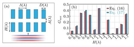
The DLA structure parameters are shown in Fig.3(a),whereHis the height of the medium,Dis the width of the medium,Λis the period length of the structure andAis the width of the acceleration channel.All length units are normalized by the incident wavelength.Since the accelerating electric field mode is an evanescent wave,increasing the value ofAwill decrease the amplitude of the accelerating mode.However, ifAis too small, it may cause difficulties in the electron injection process.Therefore, a compromise is to chooseA(λ)as 1/4.In this study,we only consider the periodic structure with more symmetry,which meansDis equal toβ/2,as shown in Table 1.

Fig.3.(a)DLA structure parameters.Only H(λ)is varied in the simulation.(b)Acceleration gradient for different parameters H(λ).
The region of the particle injection channel is of size 4λ×λ/4,β=0.8, the pillar size isH(λ)×0.4λ.A periodic condition is used to introduce plane waves into the structure from the lower side, as shown in Fig.3(a).For materials of Si, we calculated the value ofGnoron the symmetry line of the particle injection channel by using Eqs.(16) and (17).A total of 13 parameter simulations were performed,where onlyH(λ)was varied, as shown in Fig.3(b).Gnorreaches a peak of 0.43 forH(λ)=1.1.In other words,when the structure parameter of the Si pillar is 2200 nm×800 nm,an acceleration gradient of 0.43 times the initial electric field value can be provided at the center of the particle channel,which corresponds to an acceleration gradient of 0.12 GV·m-1calculated based on Refs.[40,41].It is evident that for the majority of cases,the results obtained from Eqs.(16) and (17) are extremely close,with only slight differences in a few instances.Additionally,we observe that as the value ofHincreases, the calculated results also increase or decrease.However, this trend is not strictly linear, and at times there may be small fluctuations.Therefore, the design of the accelerator needs to be analyzed on a case-by-case basis at a machinable scale.
4.2.Influence of electrons
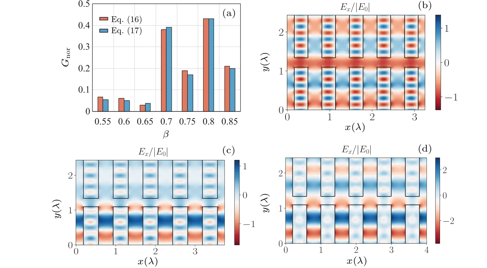
We simulate the acceleration of different electrons using the optimalHobtained from the previous simulation and analyze their impact on the acceleration.A periodic condition is used to introduce plane waves into the structure from the lower side.The region of the particle injection channel is of size 5βλ×λ/4, The pillar size isβλ/2×1.1λ.A total of seven simulations were performed, where onlyβwas varied.We calculated the value ofGnoron the symmetry line of the particle injection channel.The results of these two methods are shown in Fig.4(a).

Fig.4.Values of electric feild distribution and normalized acceleration gradient function.(a)The values of the normalized acceleration gradient function calculated by two different methods,Eqs.(16)and(17),with seven β parameters.The electric feild distributions shown in(b),(c)and(d)correspond to the simulation parameters β of 0.65,0.75 and 0.8,respectively.
The relationship betweenβandGnoris not linear but exhibits a complex nonlinear relationship.Whenβvaries between 0.55 and 0.6,the value ofGnordecreases slightly;whenβvaries between 0.6 and 0.65, the value ofGnordecreases more significantly; whenβvaries between 0.65 and 0.7, the value ofGnordrops sharply, but then rapidly rebounds after 0.7;whenβvaries between 0.7 and 0.8,the value ofGnorfluctuates widely but shows an overall upward trend; and whenβvaries between 0.8 and 0.85, the value ofGnordecreases slightly but still remains at a high level.The general trend is that asβincreases, the value ofGnorfirst increases and then decreases.It can be seen that theGnorvalues obtained by the two calculation methods are in good agreement.
We have plotted the electric field distributions in Figs.4(b),4(c)and 4(d)for beta values of 0.65,0.75 and 0.8,respectively.It is evident that the main difference between the beta values of 0.65 and 0.75/0.8 lies in the mode pattern of the electric field distribution,with the standing wave mode in the latter case being more conducive to electron acceleration.Analyzing the electric field distribution between beta values of 0.75 and 0.8, it can be observed that although standing wave modes can be excited in both cases,the strength of the excitation is different.A stronger standing wave mode is excited for a beta value of 0.8,which results in a stronger corresponding acceleration gradient.
Using Eqs.(16)and(17),we have calculated 20 different examples.These results indicate that neglecting the charge space effect during acceleration over a short distance results in highly accurate calculations of the maximum acceleration gradient using the simplified energy formula.However, it is expected that the deflection field will affect the accuracy of calculation of the maximum acceleration gradient during acceleration over a long distance, although the formula for energy gain of particles in the longitudinal direction remains valid.
4.3.Influence of material
Based on the optimal layout obtained from the previous simulation, we conducted simulations using three available materials and analyzed how the electric field distribution affects the acceleration.
The region of the particle injection channel is of size 4λ×λ/4 andβ=0.8.A periodic condition is used to introduce plane waves into the structure from the lower side,as shown in Fig.3(a).A total of three simulations were performed,where only theεparameter was varied.We calculated the value ofGnoron the symmetry line of the particle injection channel.For the materials SiO2,Si3N4and Si,the acceleration gradients achieved were 0.01,0.08 and 0.43(E0),respectively.Assuming incident field values consistent with the laser damage thresholds given in references,[40,41]these correspond to acceleration gradients of 0.003 GV·m-1, 0.11 GV·m-1and 1.8 GV·m-1,respectively.
In Figs.5(a),5(b)and 5(c),we depict the electric field distributions corresponding to SiO2, Si3N4and Si, respectively.It is evident that the primary difference among the three materials lies in the mode of electric field distribution.Specifically, the standing wave mode in Si is more conducive to electron acceleration.Si can excite a stronger standing wave mode, resulting in a stronger corresponding acceleration gradient.Therefore, this implies that the greater the refractive index contrast in the structure, the more suitable it is for particle acceleration.Therefore, this result once again confirms that a case-by-case analysis is required in the design process of the accelerator.

Fig.5.Electric field distributions of cylindrical structures with three different materials: (a)SiO2,(b)Si3N4 and(c)Si.
5.Conclusion
In this study, we establish the principles for effectively accelerating particles using dielectric structures by using basic equations, and provide a clear understanding of the physical mechanism behind acceleration by DLAs.We demonstrate how DLAs can be implemented by breaking spatial symmetry and validate our calculations using the FDFD method,which supports the use of simplified energy formulae to compute particle energy gain in large-scale simulations.We also demonstrate that effective acceleration occurs when particles in the acceleration cavity sense an electric field with zero frequency, which offers a powerful method for designing these devices.Overall, our results provide a new physical framework for understanding the mechanism of acceleration by a DLA,and have potential applications in the field of designing dielectric laser acceleration.
Acknowledgements
The authors are grateful to Fulong Liu and Qiangyou He for fruitful discussions.
Project supported by the National Natural Science Foundation of China(Grant No.11975214).
杂志排行
Chinese Physics B的其它文章
- The application of quantum coherence as a resource
- Special breathing structures induced by bright solitons collision in a binary dipolar Bose–Einstein condensates
- Effect of short-term plasticity on working memory
- Directional-to-random transition of cell cluster migration
- Effect of mono-/divalent metal ions on the conductivity characteristics of DNA solutions transferring through a microfluidic channel
- Off-diagonal approach to the exact solution of quantum integrable systems
